
The great instrument which has just completed the installation of our national observatory is constructed upon the same principle as the elbowed equatorial, 11 in. in diameter, established in 1882, according to the ingenious arrangement devised as long ago as 1872, by Mr. Loewy, assistant director of the Paris Observatory.
We shall here recall the fact that the elbowed equatorial consists of two parts joined at right angles. One of these is directed according to the axis of the world, and is capable of revolving around its own axis, and the other, which is at right angles to it, is capable of describing around the first a plane representing the celestial equator. At the apex of the right angle there is a plane mirror of silvered glass inclined at an angle of 45 deg. with respect to the optical axis, and which sends toward the ocular the image coming from the objective and already reflected by another and similar plane mirror. The objective and this second mirror (which is inclined at an angle of 45 deg.) are placed at the extremity of the external part of the tube, and form part of a cube, movable around the axis of the instrument at right angles with the axis of the world. The diagram in Fig. 3 will allow the course of a luminous ray coming from space to be easily understood. The image of the star, A, toward which the instrument is directed, traverses the objective, B C, is reflected first from the mirror, B D, and next from the central mirror, E F, and finally reaches O, at the ocular where the observer is stationed.
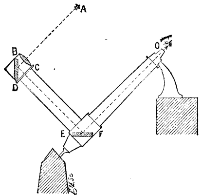
FIG 3.—DIAGRAM SHOWING THE COURSE OF
A LUMINOUS RAY IN THE GREAT EQUATORIAL.
This new equatorial differs from the first model by its much larger dimensions and its extremely remarkable mechanical improvements. The optical part, which is admirably elaborated, consists of a large astronomical objective 24 in. in diameter, and of a photographic objective of the same aperture, capable of being substituted, one for the other, according to the nature of the work that it is desired to accomplish by the aid of this colossal telescope, the total length of which is 59 ft. The two plane mirrors which complete the optical system have, respectively, diameters of 34 in. and 29 in. These two magnificent objectives and the two mirrors were constructed by the Brothers Henry, whose double reputation as astronomers and opticians is so universally established. The mechanical part is the successful work of Mr. Gautier, who has looked after every detail with the greatest care, and has thus realized a true chef d'oeuvre. The colossal instrument, the total weight of which is 26,400 lb., is maneuvered by hand with the greatest ease. A clockwork movement, due to the same able manufacturer, is capable, besides, of moving the instrument with all the precision desirable, and of permitting it to follow the stars in their travel across the heavens. A star appearing in the horizon can thus be observed from its rising to its setting. The astronomer, his eye at the ocular, is always conveniently seated at the same place, observing the distant worlds, rendered immovable, so to speak, in the field of the instrument. For stars which, like the moon and the planets, have a course different from the diurnal motion, it is possible to modify the running of the clockwork, so that they can thus be as easily followed as in the preceding case. Fig. 1 gives a general view of the new installation, for which it became necessary to build a special edifice 65 ft. in height on the ground south of the observatory bordering on the Arago Boulevard. A large movable structure serves for covering the external part of the instrument. This structure rests on rails, upon which it slides toward the south when it is desired to make observations. It will be seen from the figure how the principal axis of the instrument rests upon the two masonry pillars, one of which is 49 ft. and the other 13 ft. in height.
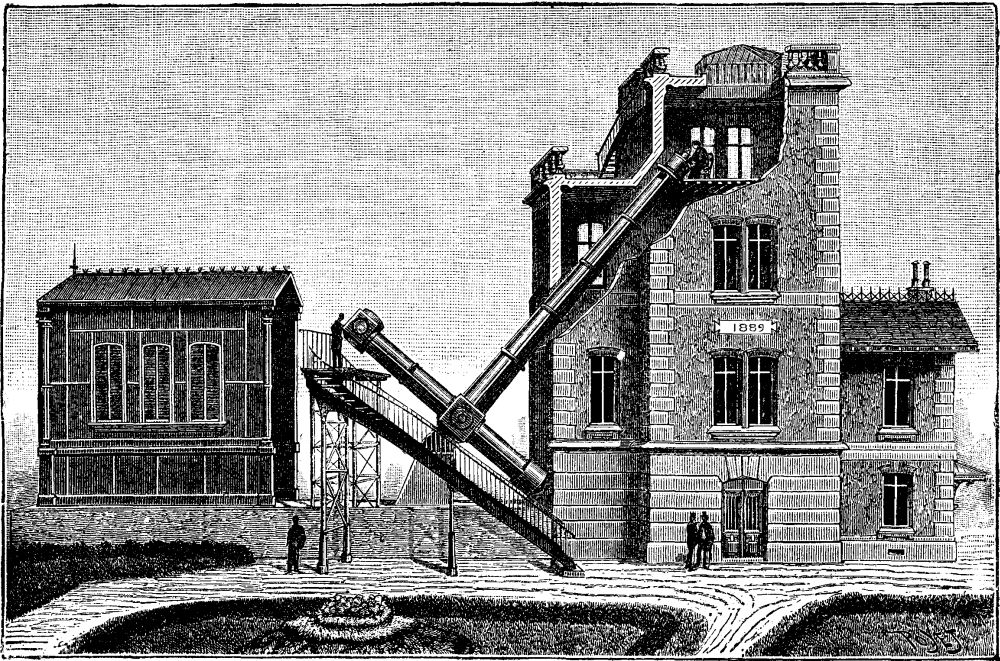
FIG 1.—THE GREAT EQUATORIAL OF THE PARIS OBSERVATORY.
The total cost of the pavilion, rolling structure, and instrument (including the two objectives) will amount to about $80,000 after the new equatorial has been provided with the scientific apparatus that necessarily have to accompany it for the various and numerous applications to which the use of it will give rise.

FIG 2.—OCULAR OF THE GREAT EQUATORIAL.
Fig. 2 shows us the room in the observatory in which the astronomer, seated in his chair, is completely protected against the inclemencies of the weather. Here, with his eye applied to the ocular, he can, without changing position (owing to all the handles that act at his will upon the many transmissions necessary for the maneuvering), direct his instrument unaided toward every point of the heavens with wonderful sureness and precision. The observer has before him on the same plane two divided circles, one of which gives the right ascensions and the other the declinations, and which he consults at each observation for the exact orientation of the equatorial.
All the readings are done by the aid of electric lamps of very small dimensions, supplied by accumulators, and which are lighted at will. Each of these lamps is of one candle power; two of them are designed for the reading of the two circles of right ascension and of declination; a third serves for the reading of the position circle of the micrometer; two others are employed for the reading of the drums fixed upon the micrometric screws; four others serve for rendering the spider threads of the reticule brilliant upon a black ground; and still another serves for illuminating the field of the instrument where the same threads remain black upon a luminous ground. The currents that supply these lamps are brought over two different circuits, in which are interposed rheostats that permit of graduating the intensity of the light at will.
Since the installation of the first model of an elbowed equatorial of 11 in. aperture, in 1882, at the Paris Observatory, the numerous and indisputable advantages of this sort of instrument have led a certain number of observatories to have similar, but larger, instruments constructed. In France, the observatories of Alger, Besancon, and Lyons have telescopes of this kind, the objectives of which have diameters of from 12 in. to 13 in., and which have been used for several years past in equatorial observations of all kinds. The Vienna Observatory has for the last two years been using an instrument of this kind whose objective has an aperture of 15 inches. Another equatorial of the same kind, of 16 in. aperture, is now in course of construction for the Nice Observatory, where it will be especially employed as a seeker of exceptional power—a role to which this kind of instrument lends itself admirably. The optical part of all these instruments was furnished by the Messrs. Henry, and the mechanical part by Mr. Gautier.
The largest elbowed equatorial is, therefore, that of the Paris Observatory. Its optical power, moreover, corresponds perfectly to its huge dimensions. The experimental observations which have already been made with it fully justify the hopes that we had a right to found upon the professional skill of the eminent artists to whom we owe this colossal instrument. The images of the stars were given with the greatest sharpness, and it was possible to study the details of the surface of the moon and other planets, and several star clusters, in all their peculiarities, in the most remarkable manner.
When it shall become possible to make use of this equatorial for celestial photography, there is no doubt that we shall obtain the most important results. As regards the moon, in particular, the photographing of which has already made so great progress, its direct image at the focus of the large 24 in. photographic objective will have a diameter of 11 in., and, being magnified, will be capable of giving images of more than 3 ft. in diameter.—La Nature.
There is no flower more truly and universally popular than the lily of the valley. What can be more delicious and refreshing than the scent of its fragrant flowers? What other plant can equal in spring the attractiveness of its pillars of pure white bells half hidden in their beautiful foliage? There are few gardens without a bed of lily of the valley, but too often the place chosen for it is some dark corner where nothing else would be expected to grow, but it is supposed as a matter of course that "it will do for a lily bed." The consequence is that although these lilies are very easy things to cultivate, as indeed they ought to be, seeing that they grow wild in the woods of this and other countries, yet one hears so often from those who take only a slight interest in practical gardening, "I have a lily bed, but I scarcely ever get any lilies." Wild lilies are hardly worth the trouble of gathering, they are so thin and poor; it is interesting to find a plant so beautiful and precious in the garden growing wild in the woods, but beyond that the flowers themselves are worth but very little. This at once tells us an evident fact about the lily of the valley, viz., that it does require cultivation. It is not a thing to be left alone in a dark and dreary corner to take care of itself anyhow year after year. People who treat it so deserve to be disappointed when in May they go to the lily bed and find plenty of leaves, but no flowers, or, if any, a few poor, weak attempts at producing blossoms, which ought to be so beautiful and fragrant. One great advantage of this lovely spring flower is that it can be so readily and easily forced. Gardeners in large places usually spend several pounds in the purchase of crowns and clumps of the lily of the valley, which they either import direct from foreign nurserymen or else procure from their own dealer in such things, who imports his lilies in large quantities from abroad. But we may well ask, Have foreign gardeners found out some great secret in the cultivation of this plant? Or is their climate more suitable for it? Or their soil adapted to growing it and getting it into splendid condition for forcing? It is impossible that the conditions for growing large and fine heads of this lily can be in any way better in Berlin or elsewhere than they are in our own land, unless greater heat in summer than we experience in England is necessary for ripening the growths in autumn.
There is another question certainly as to varieties; one variety may be superior to another, but surely if so it is only on the principle of the survival of the fittest, that is to say, by carefully working on the finest forms only and propagating from them, a strong and vigorous stock may be the result, and this stock may be dignified with a special name. For my own part what I want is to have a great abundance of lily of the valley from February till the out-door season is over. To do this with imported clumps would, of course, be most costly, and far beyond what any person ought to spend on mere flowers. Though it must be remembered that it is an immense advantage to the parish priest to be able to take bright and sweet flowers to the bedside of the sick, or to gratify the weary spirit of a confirmed invalid, confined through all the lovely spring time to the narrow limits of a dull room, with the fragrant flowers of the lily of the valley. I determined, therefore, that I would have an abundance of early lilies, and that they should not be costly, but simply produced at about the same expense as any other flowers, and I have been very successful in accomplishing this by very simple means. First of all, it is necessary to have the means of forcing, that is to say the required heat, which in my case is obtained from an early vinery. I have seen lilies forced by pushing the clumps in under the material for making a hot bed for early cucumbers, the clumps being drawn out, of course, as soon as the flowers had made a good start. They have then to be carefully and very gradually exposed to full light, but often, although fine heads of bloom may be produced in this way, the leaves will be few and poor.
My method is simply this: In the kitchen garden there is the old original bed of lilies of the valley in a corner certainly, but not a dark corner. This is the reservoir, as were, from whence the regular supply of heads for special cultivation is taken. This large bed is not neglected and left alone to take care of itself, but carefully manured with leaf mould and peat moss manure from the stable every year. Especially the vacant places made by taking out the heads for cultivation are thus filled up.
Then under the east wall another piece of ground is laid out and divided into four plots. When I first began to prepare for forcing I waited four years, and had one plot planted with divided heads each year. Clumps are taken up from the reserve bed and then shaken out and the heads separated, each with its little bunch of fibrous roots. They are then carefully planted in one of the plots about 4 in. or 5 in. apart, the ground having previously been made as light and rich as possible with plenty of leaf mould. I think the best time for doing this is in autumn, after the leaves have turned yellow and have rotted away; but frequently the operation has been delayed till spring, without much difference in the result.
Asparagus is usually transplanted in spring, and there is a wonderful affinity between the two plants, which, of course, belong to the same order. It was a long time to wait—four years—but I felt there was no use in being in too great a hurry, and every year the plants manifestly improved, and the buds swelled up nicely and looked more plump each winter when the leaves were gone. It must be remembered also that a nice crop of flowers could be gathered each year. When the fourth year came, the first plot was divided up into squares about 2 ft. each way, and taken up before any hard frost or snow had made their appearance, and put away on the floor of an unused stable. From the stable they are removed as required in the squares to the vinery, where they grow beautifully, not sending up merely fine heads of bloom without a vestige of leaf, but growing as they would in spring out of doors with a mass of foliage, among which one has to search for the spikes of flower, so precious for all sorts of purposes at that early season of the year.
The spikes produced in this way do not equal in thickness and substance of petal the flowers which come from more carefully prepared clumps imported from Berlin, but they are fine and strong, and above all most abundant. I can not only supply the house and small vases for the church, but also send away boxes of the flowers to friends at a distance, besides the many gifts which can be made to those who are ill or invalids. Few gifts at such a time are more acceptable than a fragrant nosegay of lily of the valley. In order to keep the supply of prepared roots ready year after year, a plot of ground has only to be planted each autumn, so that in the rotation of years it may be ready for forcing when its turn shall come.
As the season advances, as every one knows who has attempted to force the lily of the valley, much less time is taken in bringing the flowers to perfection under precisely the same circumstances as those in which the first sods are forced. In February or earlier the buds are more unwilling to start; there seems to be a natural repugnance against being so soon forced out of the winter's sleep and rest. But when the flowers do come, they are nearly as fine and their leaves are quite as abundant in this way of forcing as from the pieces introduced much later into heat. It would be easy to preserve the squares after all the flowers are gathered, but I found that they would not, like strawberries, kindly furnish forth another crop later on in the year, and, therefore, mine are flung away; and I have often pitied the tender leaves in the frost and snow after their short sojourn in the hot climate of the vinery. But the reserve bed will always supply an ample quantity of fresh heads, and it is best to take the new plants for preparation in the kitchen garden from this reserve bed.
This very simple method of forcing lilies of the valley is within the reach of any one who has even a small garden and a warm house, and these two things are becoming more and more common among us every day.—A Gloucestershire Parson, in The Garden.
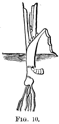
Early in June a somewhat hairy fly, Fig. 9, may be seen flying about, and depositing its eggs on the leaves of the young onion plants, near the roots, Fig. 10.
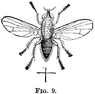
Dr. Fitch describes this fly as follows: "It has a considerable resemblance to the common house fly, though when the two are placed side by side, this is observed as being more slender in its form. The two sexes are readily distinguished from each other by the eyes, which in the males are close together, and so large as to occupy almost the whole surface of the head, while in the females they are widely separated from each other. These flies are of an ash gray color, with the head silvery, and a rusty black stripe between the eyes, forked at its hind end. And this species is particularly distinguished by having a row of black spots along the middle of the abdomen or hind body, which sometimes run into each other, and then forming a continuous stripe.
"This row of spots is quite distinct in the male, but in the female is very faint, or is often wholly imperceptible. This fly measured 0.22 to 0.25 inch in length, the females being usually rather larger than the males." The eggs are white, smooth, somewhat oval in outline, and about one twenty-fifth of an inch in length. Usually not more than half a dozen are laid on a single plant, and the young maggot burrows downward within the sheath, leaving a streak of pale green to indicate its path, and making its way into the root, devours all except the outer skin.
The maggots reach their full growth in about two weeks, when they are about one-third of an inch long, white and glossy, tapering from the posterior end to the head, which is armed with a pair of black, hook-like jaws. The opposite end is cut off obliquely and has eight tooth-like projections around the edge, and a pair of small brown tubercles near the middle. Fig. 11 shows the eggs, larva, and pupa, natural size and enlarged.
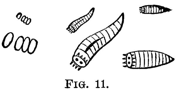
They usually leave the onions and transform to pupæ within the ground. The form of the pupa does not differ very much from the maggot, but the skin has hardened and changed to a chestnut brown color, and they remain in this stage about two weeks in the summer, when the perfect flies emerge. There are successive broods during the season, and the winter is passed in the pupa stage.
The following remedies have been suggested:
Scattering dry, unleached wood ashes over the plants as soon as they are up, while they are wet with dew, and continuing this as often as once a week through the month of June, is said to prevent the deposit of eggs on the plants.
Planting the onions in a new place as remote as possible from where they were grown the previous year has been found useful, as the flies are not supposed to migrate very far.
Pulverized gas lime scattered along between the rows has been useful in keeping the flies away.
Watering with liquid from pig pens collected in a tank provided for the purpose, was found by Miss Ormerod to be a better preventive than the gas lime.
When the onions have been attacked and show it by wilting and changing color, they should either be taken up with a trowel and burned, or else a little diluted carbolic acid, or kerosene oil, should be dropped on the infested plants to run down them and destroy the maggots in the roots and in the soil around them.
Instead of sowing onion seed in rows, they should be grown in hills, so that the maggots, which are footless, cannot make their way from one hill to another.
In the New England States there are three broods of this insect in a year, according to Mr. Scudder, the butterflies being on the wing in May, July, and September; but as the time of the emergence varies, we see them on the wing continuously through the season.
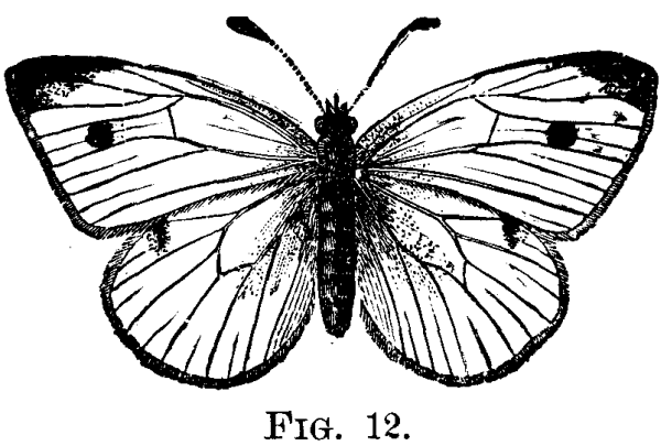
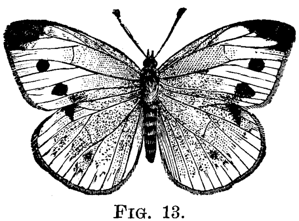
The expanded wings, Fig. 12, male, measure about two inches, are white above, with the base dusky. Both sexes have the apex black and a black spot a little beyond the middle, and the female, Fig. 13, has another spot below this. The under side of the fore wings is white, yellowish toward the apex, and with two black spots in both sexes corresponding to those on the upper side of the female. A little beyond the middle of the costa, on the hind wings, is an irregular black spot on the upper surface, while the under surface is pale lemon yellow without marks, but sprinkled more or less with dark atoms. The body is black above and white beneath.
The caterpillars of this insect feed on the leaves of cabbage, cauliflower, turnip, mignonette, and some other plants.
The female lays her eggs on the under side of the leaves of the food plants, generally, but sometimes on the upper sides or even on the leaf stalks. They are sugar loaf shaped, flattened at the base, and with the apex cut off square at the top, pale lemon yellow in color, about one twenty-fifth of an inch long and one fourth as wide, and have twelve longitudinal ribs with fine cross lines between them.
The eggs hatch in about a week, and the young caterpillars, which are very pale yellow, first eat the shells from which they have escaped, and then spin a carpet of silk, upon which they remain except when feeding. They now eat small round holes through the leaves, but as they grow older change to a greenish color, with a pale yellow line along the back, and a row of small yellow spots along the sides, and eat their way down into the head of the cabbage.
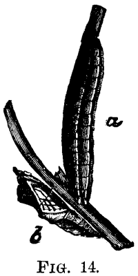
Having reached its full growth, the caterpillar, Fig. 14, a, which is about an inch in length, wanders off to some sheltered place, as under a board, fence rail, or even under the edge of clapboards on the side of a building, where it spins a button of silk, in which to secure its hind legs, then the loop of silk to support the forward part of the body.
It now casts its skin, changing to a chrysalis, Fig. 14, b, about three-fourths of an inch in length, quite rough and uneven, with projecting ridges and angular points on the back, and the head is prolonged into a tapering horn. In color they are very variable, some are pale green, others are flesh colored or pale ashy gray, and sprinkled with numerous black dots. The winter is passed in the chrysalis stage.
After the caterpillar changes to a chrysalis, their minute parasites frequently bore through the outside and deposit their eggs within. These hatch before the time for the butterflies to emerge, and feeding on the contents, destroy the life of the chrysalis.
Birds and spiders are of great service in destroying these insects.
The pupæ should be collected and burned if the abdomen is flexible; but if the joints of the abdomen are stiff and cannot be easily moved, they should be left, as they contain parasites.
Several applications of poisons have been used, the best results being obtained from the use of pyrethrum as a powder blown on to the plants by a hand bellows, during the hottest part of the day, in the proportion of one part to four or five of flour.
As the eggs are laid at different times, any application, to be thoroughly tested, must be repeated several times.
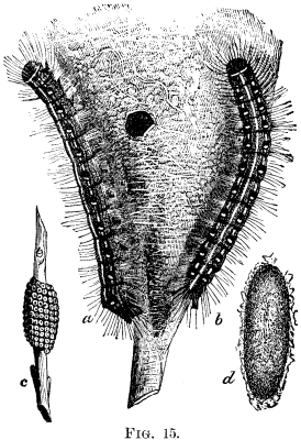
Large, white, silken web-like tents, Fig. 15, are noticed by the roadsides, in the early summer, on wild cherry trees, and also on fruit trees in orchards, containing numerous caterpillars of a blackish color, with fine gray hairs scattered over the body.
This well known pest has been very abundant throughout the State for several years past, and the trees in many neglected orchards have been greatly injured by it, some being entirely stripped of their leaves. The trees in these orchards and the neglected ones by the roadsides form excellent breeding places for this insect, and such as are of little of no value should be destroyed. If this were well done, and all fruit growers in any given region were to destroy all the tents on their trees, even for a single season, the work of holding them in check or destroying them in the following year would be comparatively light.
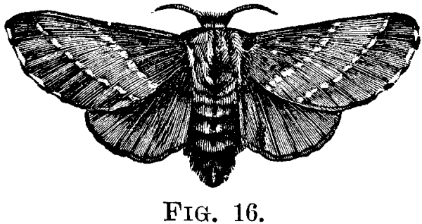
The moths, Fig. 16, appear in great numbers in July, their wings measuring, when expanded, from one and a quarter to one and a half inches or more. They are of a reddish brown color, the fore wings being tinged with gray on the base and middle, and crossed by two oblique whitish stripes.
The females lay their eggs, about three hundred in number, in a belt, Fig. 15, c, around the twigs of apple, cherry, and a few other trees, the belt being covered by a thick coating of glutinous matter, which probably serves as a protection against the cold weather during winter.
The following spring, when the buds begin to swell, the egg hatch and the young caterpillar seek some fork of a branch, where they rest side by side. They are about one-tenth of an inch long, of a blackish color, with numerous fine gray hairs on the body. They feed on the young and tender leaves, eating on an average two apiece each day. Therefore the young of one pair of moths would consume from ten to twelve thousand leaves; and it is not uncommon to see from six to eight nests or tents on a single tree, from which no less than seventy-five thousand leaves would be destroyed—a drain no tree can long endure.
As the caterpillars grow, a new and much larger skin is formed underneath the old one, which splits along the back and is cast off. When fully grown, Fig. 15, a and b, which is in about thirty-five to forty days after emerging from the eggs, they are about two inches long, with a black head and body, with numerous yellowish hairs on the surface, with a white stripe along the middle of the back, and minute whitish or yellowish streaks, which are broken and irregular along the sides; and there is also a row of transverse, small, pale blue spots along each side of the back.
As they move about they form a continuous thread of silk from a fleshy tube on the lower side of the mouth, which is connected with the silk-producing glands in the interior of the body, and by means of this thread they appear to find their way back from the feeding grounds. It is also by the combined efforts of all the young from one belt of eggs that the tents are formed.
These caterpillars do not feed during damp, cold weather, but take two meals a day when it is pleasant.
After reaching their full growth, they leave their tents and scatter in all directions, seeking for some protected place where each one spins its spindle-shaped cocoon of whitish silk intermingled with sulphur colored powder, Fig. 15, d. They remain in these cocoons, where they have changed to pupæ, from twenty to twenty-five days, after which the moths emerge, pair, and the females lay their eggs for another brood.
Several remedies have been suggested, a few of which are given below. Search the trees carefully, when they are bare, for clusters of eggs; and, when found, cut off the twigs to which they are attached, and burn them.
As soon as any tents are observed in the orchard they should be destroyed, which may be readily and effectually done by climbing the trees, and with the hand protected by a mitten or glove, seize the tent and crush it with its entire contents; also swab them down with strong soapsuds or other substances; or tear them down with a rounded bottle brush.
Burning with a torch not only destroys the caterpillars but injures the trees.
It should be observed, however, since the caterpillars, are quite regular in taking their meals, in the middle of the forenoon and afternoon, that they should be destroyed only in the morning or evening, when all are in the tent.
Another remedy is to shower the trees with Paris green in water, in the proportion of one pound to one hundred and fifty gallons of water.
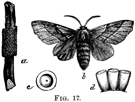
This species, commonly known as the forest tent caterpillar, closely resembles the apple tree tent caterpillar, but does not construct a visible tent. It feeds on various species of forest trees, such as oak, ash, walnut, hickory, etc., besides being very injurious to apple and other fruit trees. The moth, Fig. 17, b, expands an inch and a half or more. The general color is brownish yellow, and on the fore wings are two oblique brown lines, the space between them being darker than the rest of the wing. The eggs, Fig. 17, c and d, which are about one twenty fifth of an inch long and one fortieth wide, are arranged, three or four hundred in a cluster, around the twigs of the trees, Fig. 17, a. These clusters are uniform in diameter and cut off squarely at the ends. The eggs are white, and are firmly fastened to the twigs and to each other, by a brown substance, like varnish, which dries, leaving the eggs with a brownish covering.
The eggs hatch about the time the buds burst, or before, and the young caterpillars go for some time without food, but they are hardy and have been known to live three weeks with nothing to eat, although the weather was very cold.
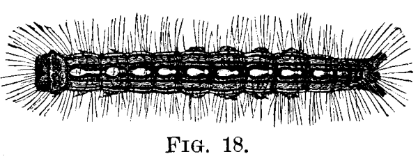
As soon as hatched they spin a silken thread wherever they go, and when older wander about in search for food. The caterpillars are about one and a half inches long when fully grown, Fig. 18. The general color is pale blue, tinged with greenish low down on the sides, and everywhere sprinkled with black dots or points, while along the middle of the back is a row of white spots each side of which is an orange yellow stripe, and a pale, cream yellow stripe below that. These stripes and spots are margined with black. Each segment has two elevated black points on the back, from each of which arise four or more coarse black hairs. The back is clothed with whitish hairs, the head is dark bluish freckled with black dots, and clothed with black and fox-colored hairs, and the legs are black, clothed with whitish hairs.
At this stage the caterpillars may be seen wandering about on fences, trees, and along the roads in search of a suitable place to spin their cocoons, which are creamy white, and look very much like those of the common tent caterpillar, except that they are more loosely constructed.
Within the cocoons, in two or three days they transform to pupæ of a reddish brown color, densely clothed with short pale yellowish hairs. The moths appear in two or three weeks, soon lay their eggs and then die. The insects are not abundant many years in succession, as their enemies, the parasites, increase and check them.
Many methods have been suggested for their destruction, but the most available and economical are to remove the clusters of eggs whenever found, and burn them, and to shower the trees with Paris green in the proportion of one pound to one hundred and fifty gallons of water.
The perfect moth, Fig. 19, 1, expands from one to one and a half inches. The fore wings are a mouse gray color, tinged with lilac and sprinkled with fine yellow dots, and distinguished mainly by a white band extending across the outer part. The moths hibernate in the perfect state, and in April or May deposit their eggs singly on the outside of the plant upon which the young are to feed. As soon as the eggs hatch, which is in about a month, the young larvæ, or caterpillars, gnaw their way from the outside into the pith.
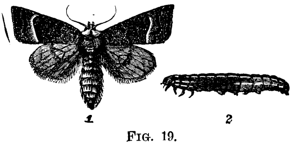
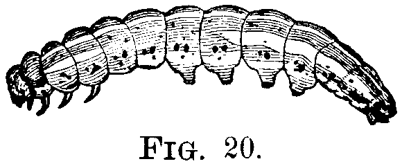
The plant does not show any sign of decay until the caterpillar is fully grown, when it dies. The caterpillar, Fig. 19, 2, is about one and one-fourth inches long, of a reddish brown color, with whitish stripes along the body. The stripes on the sides are not continuous, and the shading of the body varies, being darker on the anterior than on the posterior portion. When fully grown, Fig. 20, the color is lighter and the stripes are broader. At this stage of life it burrows into the ground just beneath the surface, and changes into the pupa state. The pupa is three-fourths of an inch long, and of a mahogany brown color. The perfect moth appears about the first of September, and there is only one brood in a season.
The caterpillars feed in the stalks of corn, tomatoes, potatoes, dahlias, asters, and also in young currant bushes, besides feeding on many species of weeds. By a close inspection of the plants about the beginning of July, the spot where the borer entered, which is generally quite a distance from the ground, may be detected, and the caterpillar cut out without injury to the plant. This plan is impracticable for an extensive crop, but by destroying the borers found in the vines that wilt suddenly, one can lessen the number another year.
This caterpillar, Fig. 21, is generally found on grapevines early in June, but also feeds on apple, plum, raspberry, maple, poplar, etc. It is about an inch and a half in length, with the body tapering toward the head; of a whitish green color, darker on the sides; with a longitudinal white stripe on the back, broader on the last segments. Low down on each side is a bright yellow stripe, between this and the one on the back is another less distinct, and the under surface of the body is pale green.
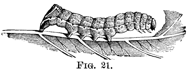
The caterpillar is fully grown about the middle or last of June, when it descends to the ground, draws together some of the fallen leaves, and makes a cocoon, in which it soon changes to a mahogany brown pupa.
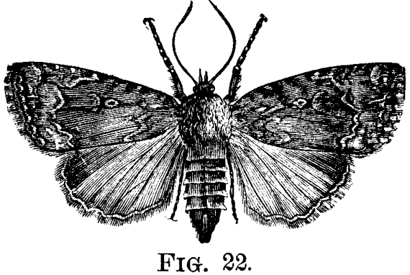
In the latter part of July the perfect moth, Fig. 22, emerges, measuring, when its wings are expanded, about one and three-fourths inches; the fore wings are dark brown shaded with lighter, with dots and wavy lines of dull white. The hind wings are reddish, or of a bright copper color, shading to brown on the outer angle of the front edge of the wing, and paler toward the hinder and inner angle.
The under surface of the wings is lighter than the upper, and the body is dark brown, with its posterior portion banded with lines of a paler hue.
This pest may be destroyed by hand picking, or by jarring the trees or vines on which they are feeding, when they will fall to the ground and may be crushed or burned.
The moths emerge and fly early in June, and are quite small, measuring, when the wings are expanded, only two-fifths of an inch, Fig. 23, a, enlarged. The fore wings are purplish or slate brown from the base to the middle, the outer half being irregularly marked with dark and light brown.
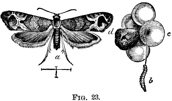
These insects are two-brooded and the first brood feeds not only on the leaves of the grape, but on tulip, sassafras, vernonia and raspberry. The caterpillars of the second brood emerge when the grapes are nearly grown, and bore in them a winding channel to the pulp, continuing to eat the interior of the berry till the pulp is all consumed, Fig. 23, d, when, if not full grown, they draw one or two other berries close to the first and eat the inside of those.
The mature caterpillar, Fig. 23, b, measures about half an inch in length, is dull greenish, with head and thoracic shield somewhat darker; the internal organs give the body a reddish tinge. It then leaves the grape and forms its cocoon by cutting out a piece of a leaf, leaving it hinged on one side; then rolling the cut end over, fastens it to the leaf, thus making for itself a cocoon in which to pupate. The pupa is dark reddish brown.
The second generation passes the winter in the pupa state, attached to leaves which fall to the ground; therefore, if all the dead and dried leaves be gathered in the fall and burned, also all the decayed fruit, a great many of these insects would be destroyed. As the caterpillars feed inside of the berry, no spraying of the vines with poisons would reach them. The caterpillar makes a discolored spot where it enters the berry, Fig. 23, c. Therefore the infested fruit may be easily detected and destroyed.
There is a small parasite that attacks this insect and helps to keep it in check. The insect has been known in Europe over a hundred years. It is not certain when it was introduced into America, but it is now found from Canada to the Gulf of Mexico, and from the Atlantic to the Pacific Ocean.
This well known insect has a world-wide reputation, and is now found wherever apples are raised.
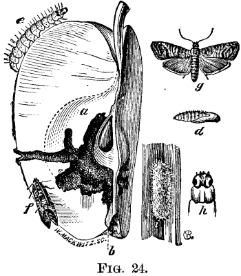
The moths are on the wing about the time the young apples are beginning to set, and the female lays a single egg in the blossom end of each apple. The fore wings of the moths when expanded, Fig. 24, g (f, with the wings closed), measure about half an inch across, and are marked with alternate wavy, transverse streaks of ashy gray and brown, and have on the inner hind angle a large tawny brown, horseshoe shaped spot, streaked with light bronze or copper color. The hind wings and abdomen are light brown with a luster of satin.
Each female lays about fifty eggs, which are minute, flattened, scale-like bodies of a yellowish color. In about a week the eggs hatch and the tiny caterpillar begins to eat through the apple to the core, Fig. 24, a, pushing its castings out through the hole where it entered, Fig. 24, b. Oftentimes these are in sight on the outside in a dark colored mass, thus making wormy apples plainly seen at quite a distance.
The caterpillar is about two-fifths of an inch in length, of a glossy, pale yellowish white color, with a light brown head. The skin is transparent and the internal organs give to it a reddish tinge.
When mature the caterpillars, Fig. 24, e, top of head and second segment, h, emerge from the apples and seek some sheltered place, such as crevices of bark, or corners of the boxes or barrels in which the fruit is stored, where they spin a tough whitish cocoon, Fig. 24, i, in which they remain unchanged all winter, and transform to pupæ, Fig. 24, d, the next spring, the perfect moths emerging in time to lay their eggs in the new crop of apples.
One good remedy is to gather all the fallen apples, and feed them to hogs; another is to let swine and sheep run in the orchard, and eat the infested fruit.
It has been recommended to place bands of cloth or hay around the trunks of the trees for the caterpillars to spin their cocoons beneath, and to remove them at the proper time, and put them in scalding water to destroy the worms.
By far the most successful method as yet adopted is to shower the apple trees with Paris green in water, one pound to one hundred and fifty gallons of water, when the apples are about the size of peas, and again in about a week.
The cabbage leaf miner is not a native of this country, but was imported from Europe.
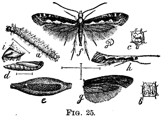
The perfect moth, Fig. 25, f, with the wings expanded (h, with the wings closed, g, a dark variety), measures three-quarters of an inch. The fore wings are ashy gray, and on the hinder margin is a white or yellowish white stripe having three points extending into the gray, thus forming, when the wings are closed, three diamond-shaped white spots. Generally there is a dark brown stripe between the white and the gray. There are also black dots scattered about on the anterior part of these wings.
The hind wings are leaden brown, and the under side of all the wings is leaden brown, glossy, and without any dots.
The antennæ are whitish with dark rings, and the abdomen white. There are two broods of this insect in this region, the moths of the first appearing in May, and those of the second in August. They hibernate in the pupa stage.
The caterpillars, Fig. 25, a (b, the top and c, the side of a segment), appear in June or July and September; they are small and cylindrical, tapering at both ends, pale green, and about one-fourth of an inch long. The head has a yellowish tinge, and there are several dark stiff hairs scattered over the body.
When ready to transform, this caterpillar spins a delicate gauze-like cocoon, Fig. 25, e, made of white, silken threads, on the under side of a cabbage leaf. The pupa, Fig. 25, d, and i, the end of a pupa, is commonly white, sometimes shaded with reddish brown, and can be distinctly seen through the silken case.
The first brood is more injurious than the second, as it feeds on the young cabbage leaves before the head is formed, and this must surely stunt the growth and make weak, sickly plants; while the second brood feeds only on the outside leaves. The caterpillars are very active, wriggling violently when disturbed, and falling by a white silken thread.
Hot dry weather is favorable to them and enables them to multiply rapidly. Advantage has been taken of this fact, and spraying the plants thoroughly with water is strongly recommended. Prof. Riley states that the insects are very readily destroyed by pyrethrum. There are two species of spiders and a species of ichneumon fly that destroy them.
The caterpillars of this species draw together the young grape leaves, Fig. 26, a, in the spring, with fine silken threads, and feed on the inside, thus doing much damage in proportion to their size. These caterpillars, Fig. 26, a, and e, a segment greatly enlarged, are full grown in about two weeks, when they are about one-fourth of an inch long, pale green with whitish hairs arising from a transverse row of warts on each segment.
Early in June they transform to pupæ, Fig. 26, b, which are pale green at first and change to dark brown. The surface is rough and the head is cut off obliquely, while on the upper side near the middle are two sharp pointed horns, Fig. 26, c. They remain in this stage from a week to ten days, when the moths emerge.
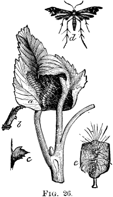
The moths, Fig. 26, d, belong to the family commonly known as plume moths or feather wings (Pterophoridæ), from having their wings divided into feather-like lobes. When the wings are expanded they measure about seven-tenths of an inch across. They are yellowish brown with a metallic luster, and have several dull whitish streaks and spots. The fore wings are split down the middle about half way to their base, the posterior half having a notch in the outer margin. The body is somewhat darker than the wings.
It is not known positively in what stage the winter is passed, but it is supposed to be the perfect, or imago stage. The unnatural grouping and spinning of the leaves together leads to their detection, and they can be easily destroyed by hand picking and then crushing or burning them.
The dog exhibitions that have annually taken place for the last eight years at Paris and in the principal cities of France have shown how numerous and varied the breeds of dogs now are. It is estimated that there are at present, in Europe, about a hundred very distinct and very fine breeds (that is to say, such as reproduce their kind with constant characters), without counting a host of sub-breeds or varieties that a number of breeders are trying to fix.
Most of the breeds of dogs, especially those of modern creation, are the work of man, and have been obtained by intercrossing older breeds and discarding all the animals that departed from the type sought. But many of these breeds are also the result of accident, or rather of modifications of certain parts of the organism—of a sort of rachitic or teratological degeneration which has become hereditary and has been due to domestication; for it is proved that the dog is the most anciently domesticated animal, and that its submission to man dates back to more than five thousand years. Such is the origin of the breeds of terriers, bulldogs, and all of the small house dogs.
Man has often, designedly or undesignedly, aided in the production of breeds of this last category by submitting the dog to a regimen contrary to nature, or setting to work to reproduce an animal born monstrous, either for curiosity or for interest. As well known, the accidental characters and the spontaneous modifications which work no injury to the essential functions of life became easily hereditary, and the same is the case with certain artificial modifications pursued for a long series of generations.
It was the opinion of Buffon that the breeds of dogs, which were already numerous in his time, were all derived from a single type, which, according to him, was the shepherd's dog. Other scientists have insisted that the dog descended from the wolf, and others from the jackal. At the present time, it is rightly admitted that several species of wild dogs have concurred in the formation of the different breeds of dogs as we now have them.
In the lacustrine habitations of the stone age in Sweden, and in the kjoekkenmoedding (kitchen remains) of Denmark, of the same epoch, we find the remains of a dog, which, according to Rutymeyer, belongs to a breed which is constant up to its least details, and which is of a light and elegant conformation, of medium size, with a spacious and rounded cranium and a short, blunt muzzle, and a medium sized jaw, the teeth of which form a regular series.
This dog, which has been named by geologists Canis palustris, fully resembles in size, slenderness of the limbs, and weakness of the muscular insertions, the spaniel, the brach hound, or the griffon.
This dog of the stone age is entirely distinct from the wolf and jackal, of which some regard the domestic dog as a descendant, and as it has appeared in Denmark as well as in Sweden, there is no doubt that this species, peculiar to Europe, was subjugated by man and used by him, in the first place, for hunting, and later on for guarding houses and cattle. Later still, in the age of metals, we observe the appearance, both in Denmark and Sweden, of larger and stronger breeds of dogs, having in their jaws the character of mastiffs, and probably introduced by the first emigrants from Asia.
There are, moreover, historic proofs that the dogs of the strongest breeds are indigenous to Asia, where we still find the dog of Thibet, the most colossal of all; in fact, in Pliny we read the following narrative: Alexander the Great received from a king of Asia a dog of huge size. He wished to pit it against bears and wild boars, but the dog remained undisturbed and did not even rise, and Alexander had it killed. On hearing of this, the royal donor sent a second dog like the first, along with word that these dogs did not fight so weak animals, but rather the lion and the elephant, and that he had only two of such individuals, and in case that Alexander had this one killed, too, he would no longer find his equal. Alexander matched this dog with a lion and then with an elephant, and he killed them both. Alexander was so afflicted at the premature death of the first dog, that he built a city and temples in honor of the animal.
Did the mountainous province of Epirus called Molossia, in ancient Greece, give its name to the molossi that it produced, or did these large dogs give their name to the country? At all events, we know that it was from Epirus that the Romans obtained the molossi which fought wild animals in the circuses, and that from Rome they were introduced into the British islands and have became the present mastiffs.
Although our hunting and shepherd's dogs have a European and the mastiffs an Asiatic ancestry, the ancestry of the harriers is African, and especially Egyptian; in fact, in Upper Egypt we find a sort of large white jackal (Simenia simensis) with the form of a harrier, and which Paul Gervais regarded with some reason as the progenitor of the domestic harrier, and a comparison of their skulls lends support to this opinion.
A study of the most ancient monuments of the Pharaohs shows that the ancient Egyptians already had at least five breeds of dogs: two very slim watch dogs, much resembling the harrier, a genuine harrier, a species of brach hound and a sort of terrier with short and straight legs. All these dogs had erect ears, except the brach, in which these organs were pendent, and this proves that the animal had already undergone the effects of domestication to a greater degree than the others. The harrier of the time of the Pharaohs still exists in great numbers in Kordofan, according to Brehm.
Upon the whole, we here have, then, at least three stocks of very distinct dogs: 1, a hunting or shepherd's dog, of European origin; 2, a mastiff, typical of the large breed of dogs indigenous to Asia; and 3, a harrier, indigenous to Africa.
We shall not follow the effects of the combination of these three types through the ages, and the formation of the different breeds; for that we shall refer our readers to a complete work upon which we have been laboring for some years, and two parts of which have already appeared.1
We shall rapidly pass in review the different breeds of dogs that one may chance to meet with in our dog shows, beginning with the largest. It is again in mountainous countries that the largest dogs are raised, and the character common to all of these is a very thick coat. The largest of all, according to travelers, is the Thibetan dog. Buffon tells of having seen one which, when seated, was five feet in height. One brought back by the Prince of Wales from his voyage to the Indies was taller in stature, stronger and more stocky than a large mastiff, from which it differed, moreover, in its long and somewhat coarse hair, which was black on the back and russet beneath, the thighs and the tail being clothed with very long and silky hair.
In France, we have a beautiful mountain dog—the dog of the Pyrenees—which is from 32 to 34 inches in height at the shoulders, and has a very thick white coat, spotted above with pale yellow or grayish fox color. It is very powerful, and is capable of successfully defending property or flocks against bears and wolves.
The Alpine dog is the type of the mountain dog. It is of the same size as the dog of the Pyrenees, and differs therefrom especially in its coloring. It is white beneath, with a wide patch of orange red covering the back and rump. The head and ears are of the same color, with the addition of black on the edges; but the muzzle is white, and a stripe of the same color advances upon the forehead nearly up to the nape of the neck. The neck also is entirely white. There are two varieties of the Alpine or St. Bernard dog, one having long hair and the other shorter and very thick hair. We give in Fig. 1 a portrait of Cano, a large St. Bernard belonging to Mr. Gaston Leonnard.

FIG.1—LARGE ST. BERNARD DOG BELONGING TO MR. LEONARD.
Although this breed originated at the celebrated convent of St. Bernard, it no longer exists there in a state of purity, and in order to find fine types of it we have to go to special breeders of Switzerland and England. The famous Plinnlimon, which was bought for $5,000 by an American two or three years ago, and about which there was much talk in the papers, even the political ones, was born and reared in England. It appears that it is necessary, too, to reduce the number of life-saving acts that it is said are daily performed by the St. Bernard dogs. This is no longer but a legend. There was, it is true, a St. Bernard named Barry, now exhibited in a stuffed state in the Berne Museum, which accomplished wonders in the way of saving life, but this was an exception, and the reputation of this animal has extended to all others of its kind. These latter are simply watch dogs kept by the monks for their own safety, and which do not go at all by themselves alone to search for travelers that have lost their way in the snow.
The Newfoundland dog, which differs from the preceding in its wholly black or black and white coat, was, it appears, also of mountain origin. According to certain authors, it is indigenous to Norway, and was carried to Newfoundland by the Norwegian explorers who discovered the island. Adapted to their new existence, they have become excellent water dogs, good swimmers, and better life savers by far than the majority of their congeners.
Is it from descending to the plain that the mountain dogs have lost their long hair and have become short haired dogs like the English dog or mastiff and the German or large Danish dogs? It is very probable. At all events, it is by this character of having short hair that mastiffs are distinguished from the mountain dogs. Again, the large breed of dogs are distinguished from each other by the following characters: The mastiff is not very high at the shoulders (30 inches), but he is very heavy and thick set, with powerful limbs, large head, short and wide muzzle and of a yellowish or café-au-lait color accompanying a black face; that is to say, the ears, the circumference of the eyes and the muzzle are of a very dark color. The German or large Danish dogs constitute but one breed, but of three varieties, according to the coat: (1) those whose coat is of a uniform color, say a slaty gray or isobelline of varying depth, without any white spots; (2) those having a fawn colored coat striped transversely with black like the zebra, but much less distinctly; (3) those having a spotted coat, that is to say, a coat with a white ground strewed with irregular black spots of varying size. These, like those of the first variety are generally small-eyed. Whatever be the variety to which they belong, the German or large Danish dogs are slimmer than, and not so heavy as, the mastiffs. Some, even, are so light that it might be supposed that they had some heavier blood in their veins. They have also a longer muzzle, although square, and are quicker in gait and motions.
The largest dogs are to be met with in this breed, and the beautiful Danish dog belonging to Prof. Charcot (Fig. 2) is certainly the largest dog in France and perhaps in Europe. It measures 36 inches at the shoulders and has an osseous and muscular development perfectly in keeping with its large stature, and at the same time has admirable proportions and lightness, and its motions are comparable to those of the finest horse.

FIG. 2—DR. CHARCOT'S LARGE DANISH DOG.
Among the English dogs or mastiffs, we very frequently meet with individuals in which the upper incisors and canines are placed back of the corresponding ones in the lower jaw, this being due to a slight shortening of the bones of the upper jaw, not visible externally. This is the first degree of an artist of teratological development, which, since the middle ages, has become very marked in certain subjects, and has given rise to a variety in which this defect has become hereditary. Such is the origin of the breed of bulldogs. The latter were originally as large as the mastiffs. Carried to Spain under Philip II., they have there preserved their primitive characters, but the bulldogs remaining in England have continued to degenerate, so that now the largest are scarcely half the size of the Spanish bulldog, and the small ones attain hardly the size of the pug, although they preserve considerable width of chest and muscular strength.
Man hunted for ages with dogs that he united in a pack; but these packs were of a very heterogeneous composition, since they included strong dogs, light dogs very swift of foot, shepherds' dogs, and others noted for acuteness of scent, and even mongrels due to a crossing with the wolf. It is from the promiscuousness of all these breeds that has arisen our ordinary modern dog.
The pointer is of relatively recent creation, and is due to the falconers. In our western countries, falconry dates from the fourth and fifth centuries, as is proved by the capitularies of Dagobert. This art, therefore, was not brought to us from the East by the crusaders in the twelfth and thirteenth centuries, as stated by Le Maout in his Natural History of Birds.
The falconer soon saw the necessity of having a dog of nice scent having for its role the finding or hunting up of game without pursuing it, in order to permit the falcons themselves to enter into the sport. This animal was called the bird dog, and was regarded as coming from various countries, especially from Spain, whence the name of spaniel that a breed of pointers has preserved. It is quite curious to find that for three or four centuries back there have been no spaniels in Spain. From Italy also and from southern climes comes what is called the bracco, whence doubtless is derived the French name braque and English brach. Finally the agasse of the Bretons was certainly also one of the progenitors of our present pointers. It was, says Oppian, a breed of small and very courageous dogs, with long hair, provided with strong claws and jaws, that followed hares on the sly under shelter of vine-stocks and reeds and sportively brought them back to their masters after they had captured them. We have certainly here the source of our barbets and griffons.
Finally the net hunters of the middle ages also contributed much to the creation of the pointer, for it is to them that we owe the setter. It is erroneously, in fact, that certain authors have attributed the creation of this dog to hunters with the arquebuse, since this weapon did not begin to be utilized in hunting until the sixteenth century. Gaston Phoebus, who died in 1391, shows, in his remarkable work, that the net hunters made use of Spanish setters and that it was they who created the true pointer—the animal that fascinates game by its gaze. By the same pull of their draw net they enveloped in its meshes both the setter and the prey that it held spellbound.
Upon the whole, we see that at the end of the middle ages there existed three types of pointers: spaniels, brachs and very hairy dogs, that Charles Estienne, in his Maison Rustique, of the sixteenth century, calls barbets. It is again with these three types that are connected all the present pointers, which we are going to pass rapidly in review.
The Brach hounds.—To-day we reserve the name of brachs for all pointers with short hair. The type of the old brach still exists in Italy, Spain, the south of France and in Germany. It is characterized by its large size, its robust form, its large head, its long, flat ears, its square muzzle separated from the forehead by a deep depression, its large nose, often double (that is to say, with nostrils separated by a deep vertical groove), its pendent lips, its thick neck, its long and strong paws provided with dew claws, both on the fore and the hind feet, and its short hair, which is usually white and marked with brown or orange-yellow spots. The old brach breed has been modified by the breeders of different countries, either by hygiene or by crossing with ordinary dogs, according to the manner of hunting, according to taste, and even according to fashion. Thus in England, where "time is money" reigns in every thing and where they like to hunt quickly and not leisurely, the brach has been rendered lighter and swifter of foot and has become the pointer. In France, while it has lost a little in size and weight, it has preserved its moderate gait and has continued to hunt near its master, "under the gun," as they say. The same is the case in Spain, Italy and Germany even. In France there are several varieties or sub-breeds of brach hounds. The old French brach, which is nothing more than the old type, preserved especially in the south, where it is called the Charles the Tenth brach, is about twenty-four inches in height, and has a white and a maroon coat, which is somewhat coarse. It often has a cleft nose and dew-claws on all the feet. The brach of the south scarcely differs from the preceding except in color. Its coat has a white ground covered with pale orange blotches and spots of the same color. The St. Germain brach is finer bred, and appears to be a pointer introduced into France in the time of Charles X. It has a very fine skin, very fine hair of a white and orange color. The Bourbon brach has the characters of the old French brach, with a white coat marked here and there with large brown blotches, and the white ground spotted with the same color; but what particularly characterizes this dog is that it is born with a stumpy tail, as if three-quarters of it had been chopped off. The Dupuy brach is slender and has a narrow muzzle, as if it had some harrier blood in its veins. It is white, with large dark maroon blotches. The Auvergne brach resembles the southern brach, but has a white and black coat spotted with black upon white. The pointer, or English brach (Fig. 3), descends from the old Spanish brach, but has been improved and rendered lighter and much swifter of foot by the introduction of the blood of the foxhound into its veins, according to the English cynegetic authors themselves. The old pointer was of a white and orange color, and was indistinguishable from our St. Germain. The pointer now fancied is white and maroon and has a stronger frame than the pointer of twenty years ago. The Italian brachs are heavy, with lighter varieties, usually white and orange color, more rarely roan, and provided with dew-claws, this being a sign of purity of breed according to Italian fanciers. The German brachs are of the type of the old brach, with a stiff white and maroon coat, the latter color being so extensively distributed in spots on the white as to make the coat very dark.
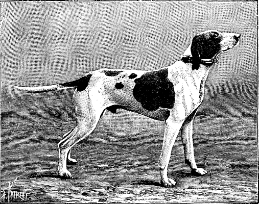
FIG 3.—POINTER.
Spaniels.—The old type of spaniel has nearly disappeared, yet we still find a few families of it in France, especially in Picardy and perhaps in a few remote parts of Germany. The old spaniel was of the same build as the brach, and differed from it in that the head, while being short-haired, was provided with ears clothed with long, wavy hair. The same kind of hair also clothed the whole body up to the tail, where it constituted a beautiful tuft. The Picard spaniel is a little lighter than the old spaniel. It has large maroon blotches upon a white ground thickly spotted with maroon, with a touch of flame color on the cheeks, over the eyes, and on the legs. The Pont-Andemer spaniel is a Norman variety, with very curly hair, almost entirely maroon colored, the white parts thickly spotted with a little color as in the Picard variety, and a characteristic forelock on the top of the head.

FIG 4.—ENGLISH SETTERS.
In England, the spaniel has given rise to several varieties. In the first place there are several sub-breeds of setters, viz.: The English setter, still called laverack, which has large black or orange-colored blotches on the head, the rest of the body being entirely white, with numerous spots of the same color as the markings on the head (Fig. 4); the Irish setter, which is entirely of a bright yellowish mahogany color; and the Gordon setter, which is entirely black, with orange color on the cheeks, under the throat, within and at the extremity of the limbs (Fig. 5). Next come the field spaniels, a group of terrier spaniels, which includes the Clumber spaniel, which is white and orange color; the Sussex spaniel, which is white and maroon; the black spaniel, which is wholly black; and the cocker, which is the smallest of all, and is entirely black, and white and maroon, or white and orange-colored, or tricolored.
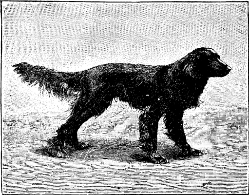
FIG 5.—GORDON SETTER.
Barbets and Griffons.—To this latter category belong the dogs, par excellence, for hunting in swamps. The barbets are entirely covered with long curly hair, like the poodles, which are directly derived from them. They are white or gray, with large black or brown blotches. The griffons differ from the poodles in their coarse and stiff hair, which never curls. They have large brown blotches upon a white ground, which is much spotted or mixed, as in the color of the hair called roan. There is an excellent white and orange-colored variety. The griffons, neglected for a long time on account of the infatuation that was and is still had for English hunting dogs, are being received again with that favor which they have never ceased to be the object of in Germany and in Italy (where they bear the name of spinone). Breeders of merit, such as Mr. Korthals, in Germany, and Mr. E. Boulet, in France, are endeavoring to bring them into prominence (Fig. 6). Finally, we reckon also among hunting dogs some very happy crosses between the spaniels and the barbets, which in England are called retrievers or water spaniels.—P. Megnin, in La Nature.
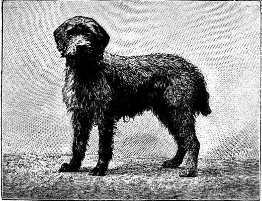
FIG 6.—COARSE HAIRED GRIFFON.
A few days ago, at Bougival, a short distance below the dam of the Marly machine, there were put into water 40,000 fry of California trout and salmon, designed to restock the Seine, which, in this region, has been depopulated by the explosions of dynamite which last winter effected the breaking up of the ice jam that formed at this place.

RESTOCKING THE SEINE WITH FISH.
The operation, which is quite simple in itself, attracted a large number of inquisitive people by reason of the exceptional publicity given to the conflict provoked by a government engineer, who, under the pretext that he had not been consulted, made objections to the submersion of the little fish. As well known, the affair was terminated by a sharp reprimand from Mr. Yves Guyot, addressed to his overzealous subordinate.
It would have been a great pity, moreover, if this interesting experiment had not taken place, and had not come to corroborate the favorable results already obtained.
In three years the California salmon reaches a weight of eleven pounds, and, from this time, is capable of reproduction. Its flesh is delicious, and comparable to that of the trout, the development of which is less rapid, but just as sure.
The fry put into the water on Sunday were but two months old. The trout were, on an average, one and a half inches in length, and the salmon two and three-quarter inches. They were transported in three iron plate vessels, weighing altogether, inclusive of the water, 770 lb., and provided with air tubes through which, during the voyage, the employes, by means of pumps, assured the respiration of the little fish.
Our engraving represents the submersion at the moment at which the cylinders (of which the temperature has just been taken and compared with that of the Seine, in order to prevent too abrupt a transition for the fry) are being carefully let down into the river.—L'Illustration.
Figures show that the consumption of iron in general construction—other than railroads—in this country has grown from a little more than a million and a half of tons in 1879 to more than six million tons in 1889. Much of this increase has gone into iron buildings. By using huge iron frames and thin curtain walls for each story supported thereon, as is done in a building going up on lower Broadway, New York city, a good deal of space can be saved.
The building of a navy, which has been actively going on for the past few years, has drawn public attention to naval subjects, and recent important experiments with armor plates have attracted large attention, hence it may not be amiss to give a description of the manufacture and testing of armor. It would be interesting to wade through the history of armor, studying each little step in its development, but we shall simply take a hasty glance at the past, and then devote our attention to modern armor and its immediate future.
Modern armor has arrived at its present state of development through a long series of experiments. These experiments have been conducted with great care and skill, and have been varied from time to time as the improvements in the manufacture of materials have developed, and as the physical laws connected with the subject have been better understood. There has been very little war experience to draw from, and hence about all that is now known has been acquired in peaceful experiments.
The fundamental object to be obtained by the use of
armor is to keep out the enemy's shot, and thus protect
from destruction the vulnerable things that may
be behind it. The first serious effort to do this dates
with the introduction of iron armor. With this form
of armor we have had a small amount of war experience.
The combat of the Monitor and Merrimac, in
Hampton Roads, in May, 1862, not only marked an
epoch in the development of models of fighting ships,
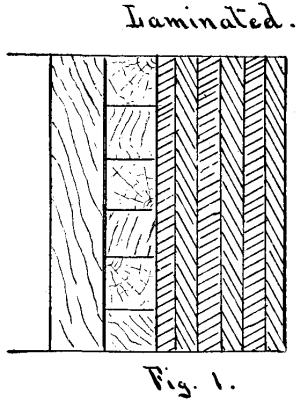
but also marked one in the use of armor. The Monitor's
turret was composed of nine one-inch plates of
wrought iron, bolted together. Plates built in this
manner form what is known as laminated armor.
(See Fig. 1.)
 The side armor of the hull was composed
of four one-inch plates. The Merrimac's casemate was
composed of four one-inch plates or two two-inch plates
backed by oak. The later monitors had laminated armor
composed of one-inch plates. The foregoing, with
the Albemarle and Tennessee rams under the Confederate
flag, are about the sum of our practical experience
in the use of armor.
The side armor of the hull was composed
of four one-inch plates. The Merrimac's casemate was
composed of four one-inch plates or two two-inch plates
backed by oak. The later monitors had laminated armor
composed of one-inch plates. The foregoing, with
the Albemarle and Tennessee rams under the Confederate
flag, are about the sum of our practical experience
in the use of armor.
European nations took up the subject of armor and energetically conducted experiments which have cost large sums of money, but have given much valuable data. For a long time wrought iron was the only material used for armor, and the resisting power depending on the thickness; and the caliber and penetration of guns rapidly increasing, it was not long before a point was reached where the requisite thickness made the load of armor so great that it was impracticable for a ship to carry it. The question then arose as to what were the most important parts of a ship to protect. The attempted solutions of this question brought out various systems of distributions.
Armored ships were formerly of two classes; in one the guns were mounted in broadside, in the other in turrets. Every part of the ship was protected with iron to a greater or less thickness. In more modern ships the guns are mounted in an armored citadel, in armored barbettes or turrets, the engines, boilers and waterline being the only other parts protected. There may be said to be three systems of armor distribution. The belt system consists in protecting the whole waterline by an armored belt, the armor being thickest abreast of the engines and boilers. The guns are protected by breastworks, turrets or barbettes, the other parts of the ship being unprotected. The French use the belt system, and our own monitors may be classed under it. The central citadel system consists in armoring that part of the waterline which is abreast of the engines and boilers. Forward and aft the waterline is unprotected, but a protective deck extends from the citadel in each direction, preventing the projectiles from entering the compartments below. The hull is divided into numerous compartments by water-tight bulkheads, and, having a reserve of flotation, the stability of the ship is not lost, even though the parts above the protective deck, forward and aft, be destroyed or filled with water. The guns are protected by turrets or barbettes. The deflective system consists in inclining the armor, or in so placing it that it will be difficult or impossible to make a projectile strike normal to the face of the plate. A plate that is inclined to the path of a projectile will, of course, offer greater resistance to penetration than one which is perpendicular; hence, when there is no other condition to outweigh this one, the armor is placed in such a manner as to be at the smallest possible angle with the probable path of the projectile. This system is designed to cause the projectile to glance or deflect on impact. Deflective armor should be at such an angle that the projectiles fired at it cannot bite, and hence the angle will vary according to the projectile most likely to be used. In the usual form of deflective deck the armor is at such a small inclination with the horizon that it becomes very effective. Turret and barbette armor may be considered as deflective armor. The term inclined armor denotes deflective armor that is inclined to the vertical. The kinds of armor that are in use may be designated as rolled iron, chilled cast iron, compound, forged and tempered steel, and nickel steel. Iron armor consists of wrought iron plates, rolled or forged, and of cast iron or chilled cast iron, as in the Gruson armor. Compound armor consists of a forged combination of a steel plate and an iron plate. Steel armor consists of wrought steel plates. Nickel-steel armor consists of plates made from an alloy of nickel and steel.
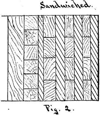
I have spoken above of laminated armor. To secure
the full benefit of this kind, the plates must be neatly
fitted to each other; the surfaces must make close contact.
This requires accurate machining, and hence is
expensive. To overcome this point sandwiched armor
was suggested. This consists in placing a layer of wood
between the laminations, as shown in Fig. 2.
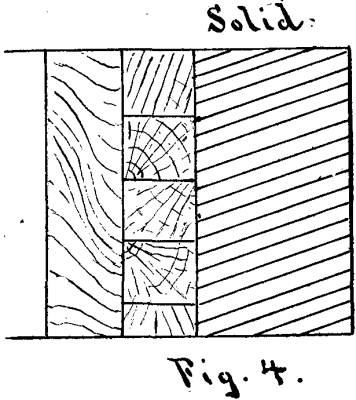
 It was
found that laminated and sandwiched armor gave very
much less resisting power than solid rolled plates
of the same thickness. Wrought iron armor is made
under the hammer or under the rolls, in the ordinary
manner of making plates, and has been exhaustively
studied and experimented with—more so than any
other form of armor.
It was
found that laminated and sandwiched armor gave very
much less resisting power than solid rolled plates
of the same thickness. Wrought iron armor is made
under the hammer or under the rolls, in the ordinary
manner of making plates, and has been exhaustively
studied and experimented with—more so than any
other form of armor.
Chilled cast iron armor is manufactured by Gruson, in Germany, and is used in sea coast defense forts of Europe.
In 1867 several compound plates were made by Chas. Cammell & Co., of Sheffield, England, and were tested at Shoeburyness, in England, and at Tegel, in Russia. These plates were made by welding slabs of steel to iron; but the difficulties were so great that the idea was abandoned for the time.
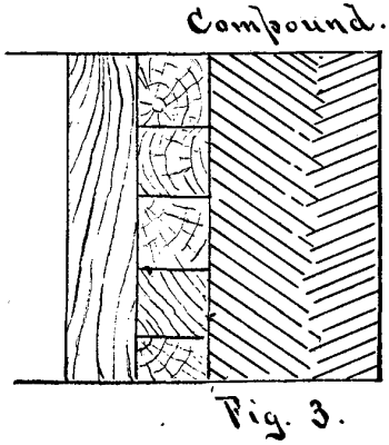
Compound armor, as now manufactured, is of two types: Wilson's patent, a backing of rolled iron, faced with Bessemer steel; Ellis' patent, a backing of rolled iron, faced with a plate of hard rolled steel, cemented with a layer of Bessemer steel. Both these kinds are manufactured in England and France in sizes up to fifty tons weight. The Wilson process is used at the works of Messrs. Cammell & Co., of Sheffield, England, and the Ellis process at the Atlas Works of Sir John Brown & Co., of the same place. These are the two leading manufacturers of compound plate.
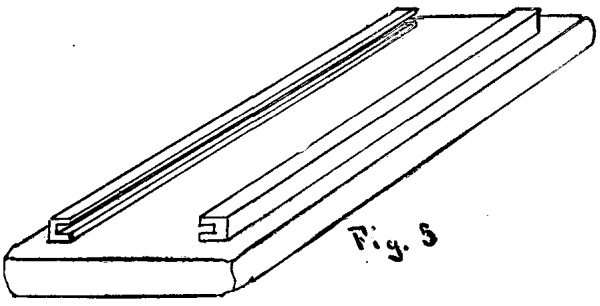
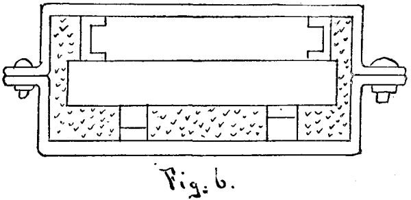
The method employed by Wilson in making compound
plate is to first make a good wrought iron
plate. To the surface of this and along each side of
the length of the plate are fixed two small channel
irons, as shown in Fig. 5.
 The plate is then raised to
a welding heat in a gas furnace, and transferred to an
iron flask or mould. Wedges are driven in between
the back of the plate and the side of the mould, thus
forcing the channel irons up snug against the opposite
side of the mould. Moulding sand is then packed
around the back and sides of the plate (see Fig. 6).
The plate is then raised to
a welding heat in a gas furnace, and transferred to an
iron flask or mould. Wedges are driven in between
the back of the plate and the side of the mould, thus
forcing the channel irons up snug against the opposite
side of the mould. Moulding sand is then packed
around the back and sides of the plate (see Fig. 6).
 The
mould is lowered in a vertical position into a pit.
Molten steel, manufactured by either the Siemens-Martin
or Bessemer process, is then poured in through
a trough that forms several streams, and forms the
hard face of the plate. The molten steel as it runs
down cleans the face of the wrought iron plate, scoring
it in places, and, being of much higher temperature,
the excessive heat carbonates the iron to a depth
of one-eighth to three-sixteenths of an inch, forming
a zone of mild steel between the hard steel and soft
iron. The mould is placed in a vertical position to insure
closeness of structure and the forcing of gases
out of the steel. After solidifying, the whole plate is
pressed, and passed through the rolls to obtain
thorough welding. It is then bent, planed, fitted,
tempered, and annealed to remove internal strains.
The
mould is lowered in a vertical position into a pit.
Molten steel, manufactured by either the Siemens-Martin
or Bessemer process, is then poured in through
a trough that forms several streams, and forms the
hard face of the plate. The molten steel as it runs
down cleans the face of the wrought iron plate, scoring
it in places, and, being of much higher temperature,
the excessive heat carbonates the iron to a depth
of one-eighth to three-sixteenths of an inch, forming
a zone of mild steel between the hard steel and soft
iron. The mould is placed in a vertical position to insure
closeness of structure and the forcing of gases
out of the steel. After solidifying, the whole plate is
pressed, and passed through the rolls to obtain
thorough welding. It is then bent, planed, fitted,
tempered, and annealed to remove internal strains.
In 1887, Wilson took out a patent for improvements
in his process of making compound plates. In this
method of manufacture he takes a wrought iron,
fibrous plate, fifteen inches thick, built up from a
number of thin plates. While hot from the forging
press, he places this plate in an iron mould (see Fig. 7)
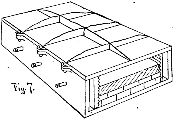 about 28 inches deep, and upon it runs "ingot iron"
or very mild steel to a depth of thirteen inches. In
this form of mould the plate rests on brickwork, and is
held in place by two grooved side clamps or strips which
are caused to grip the plate by means of screws which
extend through the sides of the mould. After solidifying,
the plate, which is twenty-eight inches thick, is
reheated and rolled down to eighteen inches. This is
the iron backing of the finished plate, and it is again
put in the iron mould and heated, when a layer of hard
steel is run on the exposed surface of the original
wrought iron plate to a depth of eight inches. This
makes a plate about twenty-eight inches thick. It is
taken from the mould, reheated, rolled, hammered or
pressed down to twenty inches. After cooling, it is
bent, planed, and fitted as desired, then tempered and
annealed to relieve internal strains.
about 28 inches deep, and upon it runs "ingot iron"
or very mild steel to a depth of thirteen inches. In
this form of mould the plate rests on brickwork, and is
held in place by two grooved side clamps or strips which
are caused to grip the plate by means of screws which
extend through the sides of the mould. After solidifying,
the plate, which is twenty-eight inches thick, is
reheated and rolled down to eighteen inches. This is
the iron backing of the finished plate, and it is again
put in the iron mould and heated, when a layer of hard
steel is run on the exposed surface of the original
wrought iron plate to a depth of eight inches. This
makes a plate about twenty-eight inches thick. It is
taken from the mould, reheated, rolled, hammered or
pressed down to twenty inches. After cooling, it is
bent, planed, and fitted as desired, then tempered and
annealed to relieve internal strains.
The method employed by Ellis in making compound
plates is to take two separate plates, one of good
wrought iron and one of hard forged steel, placing the
forged steel plate on the wrought iron plate, keeping
them separate by a wedge frame or berm of steel
around three sides, and placing small blocks of steel at
various points near the middle of the plates (see Fig. 8).
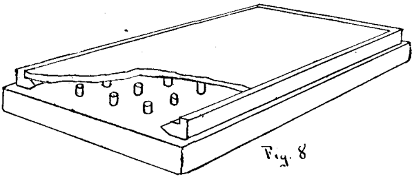 These blocks are called distance blocks. After covering
all the exposed steel surfaces with ganister, the
plates are put in a gas furnace and heated to a welding
heat. They are then lowered into a vertical iron pit
with the open side uppermost. The plates are held in
position by hydraulic rams, which also prevent bulging.
Molten steel of medium softness is then poured
into the space between the plates, by means of a distributing
trough having holes in the bottom, and after
this has solidified, the whole plate is placed under the
hydraulic press and reduced about twenty per cent. in
thickness. The plate is then passed through the rolls,
bent, planed, fitted, tempered, and annealed to reduce
internal strains.
These blocks are called distance blocks. After covering
all the exposed steel surfaces with ganister, the
plates are put in a gas furnace and heated to a welding
heat. They are then lowered into a vertical iron pit
with the open side uppermost. The plates are held in
position by hydraulic rams, which also prevent bulging.
Molten steel of medium softness is then poured
into the space between the plates, by means of a distributing
trough having holes in the bottom, and after
this has solidified, the whole plate is placed under the
hydraulic press and reduced about twenty per cent. in
thickness. The plate is then passed through the rolls,
bent, planed, fitted, tempered, and annealed to reduce
internal strains.
In heating the compound plates for rolling, the plate is placed in the furnace with the steel face down, so that the iron part gets well heated and the steel does not become too hot. Great care must be taken not to overheat the plate, and in working, many passes are given the plate with small closings of the rolls. The steel part of a compound plate is usually about one third of the full thickness of the plate.
Forged steel armor, tempered in oil, is fabricated at Le Creusot, France, by Schneider & Co., using open-hearth steel, and forging under the 100 ton hammer. The ingots are cast, with twenty-five per cent. sinking head and are cubical in form. The porter bar is attached to a lug on one side of the ingot. By means of a crane with a curved jib which gives springiness under the hammer, the ingot is thrust into the heating furnace. On arriving at a good forging heat it is swung around to the 100 ton hammer, under which it is worked down to the required shape. A seventy-five ton ingot requires about eight reheatings before being reduced to shape. Having been reduced to shape, the plate is carefully annealed, then raised to a high tempering heat, and the face tempered in oil. It is reannealed to take out the internal strains, care being taken not to reduce the face hardness more than necessary. The Schneider process of tempering is based upon the utilization of the absorption of heat caused by the fusing or melting of a solid substance, and of the fact that so long as a solid is melting or dissolving in a liquid substance, the liquid cannot get appreciably hotter, except locally around the heating surface. The body to be hardened is plunged at the requisite temperature into a bath containing the solid melting body, or is kept under pressure in the solid material of low melting point until the required extraction of heat has taken place, more solid material being added if necessary as that originally present melts and dissolves.
Nickel steel armor is made in a similar manner to the steel plates, the material used in casting the ingot being an alloy of nickel and steel containing between three and four per cent. of nickel.
The Harvey process of making armor consists in taking an all-steel plate and carbonizing the face. This carbonizing process is very similar to the cementation process of producing steel, and by it the face of the plate is made high in carbon and very hard.
The system invented by Sir Joseph Whitworth, of
Manchester, England, consists in what might be called
scale armor. A section of a sample of the armor represents
four plates. The outer layer, one inch thick, is
composed of steel of a tensile strength of 80 tons per
square inch; the second layer, one inch thick, of steel
whose tensile strength is 40 tons per square inch; the
third and fourth layers, each one-half inch thickness,
of mild steel. The outer layer is in small squares of
about ten inches on a side, and is fastened to the second
layer by bolts at the corners and one in the middle of
each square. The surface is flush. (See Fig. 9.)
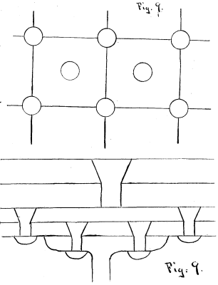 The
end sought by the above system is to break up the shot
by the hard steel face and to restrict any starring or
cracking of the metal to the limit of the squares or
scales struck. The bolts are of high carbon and are
extremely hard steel.
The
end sought by the above system is to break up the shot
by the hard steel face and to restrict any starring or
cracking of the metal to the limit of the squares or
scales struck. The bolts are of high carbon and are
extremely hard steel.
Armor plates must often be bent or curved to single or double curvature and sometimes to a warped surface to fit the form of the ship. There are several methods of bending plates. One method employs a cast iron slab of the required form, which is placed on the piston of a hydraulic press. The armor plate is placed face down on this slab, and on top of the plate are laid packing blocks of cast iron, of such sizes and shapes as to conform to the required curve. These blocks take against the upper table of the press, when the piston is forced up, and the hot plate is thus dished to the proper form.
In the French method of bending, an anvil or bed plate of the required curve is used, and the armor plate is forced to take the curve by being hammered all over its upper surface with a specially designed steam hammer.
The edges of the plate are trimmed by large, powerful slotting machines or circular saws; the latter, however, operate in exactly the same manner as a slotter, except that there is no return motion to the tool. Each tooth of the saw is but a slotting tool, and these teeth are, by screws, rendered capable of being nicely adjusted in the circumference of the saw.
The plates are fastened to the hulls and backing by heavy bolts, varying in size according to the weight of the individual plate. For the 6,000 ton armored ships, these bolts are from 2.75 to 3.1 inches in diameter and from 18.45 to 23 inches in length. They are tapped two or three inches into the armor and do not go through the plate. They pass through wrought iron tubes in the backing and set up with cups, washers and nuts against the inner skin of the ship.
At steel works where plates for our new navy are being manufactured, there are inspectors who look after the government's interests. Officers of the navy are detailed for this work, and their duty is to watch the manufacture of plates through each part of the process and to see that the conditions of the specifications and contract are complied with.
The inspection and testing of armor plates consists in examining them for pits, scales, laminations, forging cracks, etc., in determining the chemical analysis of specimens taken from different parts, in determining the physical qualities of specimens taken longitudinally and transversely, and the ballistic test. Specifications for these different tests are constantly undergoing change, and it would be impossible to state, with exactness, what the requirements are or will be in the near future. The ballistic test is the important one, and is made by taking one plate of a group and subjecting it to the fire of a suitable gun. The other tests are simply to insure, as far as practicable, that all the other plates of the group are similar to and are capable of standing as severe a ballistic test as the test plate.
The following will give an idea of the ballistic test as prescribed by the Bureau of Ordnance, Navy Department. The test plate, irrespective of its thickness, is to be backed by thirty-six inches of oak or other substantial wood. Near the middle region of the plate an equilateral triangle will be marked, each side of which will be three and one-half calibers long. The lower side of the triangle will be horizontal. Three shots will be fired, the points of impact being as near as possible the extremities of the triangle. The velocity of the shot will be such as to give the projectile sufficient energy to just pass through a wrought iron plate of equal thickness to the test plate, and through its wood backing. The velocity is calculated by the Gavre formula:
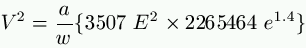
V = the velocity of the projectile in feet per second.
a = the diameter of the projectile in inches.
w = the weight of the projectile in pounds.
E = the thickness of the backing in inches.
e = the thickness of the plate in inches.
Using the above formula we can make out a table as follows:
-------+-------+-------------+-------+-------+------+---------+
Plate. |Backi'g| Gun, service|  w,   |  a,   |  V.  | Energy, |
Inches.|Inches.| shot.       |Pounds.|Inches.| f. 8.| Impact. |
       |       |             |       |       |      | f. tons.|
-------+-------+-------------+-------+-------+------+---------+
  6    |  36   |   6" B.L.R. |  100  |  5.96 | 1389 |  1337   |
  7    |  36   |   6"   "    |  100  |  5.96 | 1528 |  1619   |
  8    |  36   |   8"   "    |  250  |  7.96 | 1213 |  2550   |
  9    |  36   |   8"   "    |  250  |  7.96 | 1308 |  2966   |
 10    |  36   |   8"   "    |  250  |  7.96 | 1399 |  3390   |
 11    |  36   |   8"   "    |  250  |  7.96 | 1489 |  3839   |
 12    |  36   |  10"   "    |  500  |  9.96 | 1247 |  5386   |
 13    |  36   |  10"   "    |  500  |  9.96 | 1315 |  5987   |
 14    |  36   |  10"   "    |  500  |  9.96 | 1381 |  6608   |
 15    |  36   |  12"   "    |  850  | 11.96 | 1215 |  8699   |
 16    |  36   |  12"   "    |  850  | 11.96 | 1269 |  9710   |
 17    |  36   |  12"   "    |  850  | 11.96 | 1332 | 10454   |
 18    |  36   |  12"   "    |  850  | 11.96 | 1374 | 11124   |
 19    |  36   |  12"   "    |  850  | 11.96 | 1425 | 11965   |
 20    |  36   |  12"   "    |  850  | 11.96 | 1476 | 12837   |
-------+-------+-------------+-------+-------+------+---------+
No projectile or fragment of the plate or projectile must get wholly through the plate and backing. The plate must not break up or give such cracks as to expose the backing, previous to the third shot.
The penetration of projectiles of different forms into various styles of armor has been very thoroughly studied and many attempts have been made to bring the subject down to mathematical formulæ. These formulæ are based on several suppositions, and agree very closely with results obtained in actual experiments, but there are so many varying conditions that it is extremely doubtful if any formulæ will ever be written that will properly express the penetration.
Many different forms have been given to the heads of projectiles, as flat, ogival, hemispherical, conoidal, parabolic, blunt trifaced, etc.
The flat headed projectile has the shape of a right cylinder, and acts like a punch, driving the material of the armor plate in front of it. These projectiles are especially valuable when firing at oblique armor, for they will bite or cut into the armor when striking at an angle of thirty degrees.
The ogival head acts more as a wedge, pushing the metal aside, and generally will give more penetration in thick solid plates than the flat headed projectile. The ogival head is usually designed by using a radius of two calibers.
The hemispherical, conoidal, parabolic and blunt trifaced all give more or less of the wedging effect. The blunt trifaced has all the good qualities of the ogival of two calibers. It bites at a slightly less angle, and the three faces start cracks radiating from the point of impact.
Forged steel is the best material for armor-piercing projectiles, but many are made of chilled cast iron, on account of its great hardness and cheapness.
The best weight for a projectile is found by the formula
w = d³ (0.45 to 0.5)
w being the weight in pounds, d the diameter in inches and 0.45 to 0.5 having been determined by experiment.
With a light projectile we get a flat trajectory, and accuracy at short ranges is increased. With a heavy projectile the resistance of the air has less effect and the projectile is advantageously employed at long ranges.
In the following formulæ, used in calculating the penetration of projectiles in rolled iron armor,
  g = the force of gravity.
  w = the weight of projectile in pounds.
  d = the diameter of projectile in inches.
  v = the striking velocity in feet per second.
  P = the penetration in inches.
Major Noble, R.A., gives
![P = \sqrt[1.6]{\frac{w \ v^2}{\pi \ g \ d \ 11334.4}}](./images/tex2.png)
U.S. Naval Ordnance Proving Ground uses
![P = \sqrt[2.035]{\frac{w \ v^2}{\pi \ g \ d \ 3852.8}}](./images/tex3.png)
Col. Maitland gives
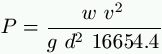
Maitland's latest formula, now used in England, is
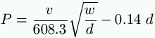
General Froloff, Russian army, gives
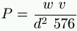
for plates less than two and one-half inches thick, and
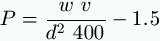
for plates more than two and one-half inches thick.
If θ be the angle between the path of the projectile and the face of the plate, then v in the above formulæ becomes v sin θ.
When we come to back the plates, their power to resist penetration becomes greater, and our formula changes. The Gavre formula, given above, is used to determine the velocity necessary for a projectile to pass entirely through an iron plate and its wood backing.
Compound and steel armor are said to give about 29 per cent. more resisting power than wrought iron, but in one experiment at the proving ground, at Annapolis, a compound plate gave over 50 per cent. more resisting power than wrought iron.
The Italian government, after most expensive and elaborate comparative tests, has decided in favor of the Creusot or Schneider all-steel plates, and has established a plant for their manufacture at Terni, near Rome.
The French use both steel and compound plates; the Russians, compound; the Germans, compound; the Swedes and Danes use both. Spain has adopted and accepted the Creusot plate for its new formidable armored vessel, the Pelayo; and China too has recently become a purchaser of Creusot plates.
Certain general rules may be laid down for attacking armor. If the armor is iron, it is useless to attack with projectiles having less than 1,000 feet striking velocity for each caliber in thickness of plate. It is unadvisable to fire steel or chilled iron filled shells at thick armor, unless a normal hit can be made. When perforation is to be attempted, steel-forged armor-piercing shells, unfilled, should be used. They may be filled if the guns are of great power as compared to the armor. Steel and compound armor are not likely to be pierced by a single blow, but continued hammering may break up the plate, and that with comparatively low-powered guns.
Wrought iron must be perforated, and hard armor, compound or steel, must be broken up. Against wrought iron plates the projectile may be made of chilled cast iron, but hard armor exacts for its penetration or destruction the use of steel, forged and tempered. Against unarmored ships, and against unarmored portions of ironclads, the value of rapid-firing guns, especially those of large caliber, can hardly be overestimated.
The relative value of steel and compound armor is much debated, and at present the rivalry is great, but the weight of evidence and opinion seems to favor the all-steel plate. The hard face of a compound plate is supposed to break up the projectile, that is, make the projectile expend its energy on itself rather than upon the plate, and the backing of wrought iron is, by its greater ductility, to prevent the destruction of the plate. It seems probable that these two systems will approach each other as the development goes on. An alloy of nickel and steel is now attracting attention and bids fair to give very good results.
The problem to be solved, as far as naval armor is concerned, is to get the greatest amount of protection with the least possible weight and volume, and this reduction of weight and volume must be accomplished, in the main, by reducing the thickness of the plates by increasing the resisting power of the material. In the compound plate great surface hardness is readily and safely attained, but it has not yet been definitely determined what the proper proportionate thickness of iron and steel is.
A considerable thickness of steel is necessary to aid, by its stiffness, in preventing the very ductile iron from giving back to such an extent as to distort the steel face and thus tear or separate the parts of the plate. The ductile iron gives a very low resisting power, its duty being to hold the steel face up to its work. If now we substitute a soft steel plate in the place of the ductile iron, we will get greater resisting power, but our compound plate then becomes virtually an all-steel one, only differing in process of manufacture. The greatest faults of the compound plate are the imperfect welding of the parts and the lack of solidity of the iron. When fired at, the surface has a tendency to chip.
In the all-steel plate we have the greatest resisting power throughout, but there are manufacturing difficulties, and surface hardness equal to that of the compound plate has not been obtained. The manufacturing difficulties are being gradually overcome, and artillerists are in high hopes that the requisite surface hardness will soon be obtained.
The following may be stated as well proved:
1. That steel armor promises to replace both iron and compound.
2. That projectiles designed for the piercing of hard
armor must be made of steel.
3. That the larger the plate, the better it is able
to absorb the energy of impact without injury to itself.
4. That the backing must be as rigid as possible.
The demand for compressed air as a motive power is constantly increasing in Paris; the company, according to its official reports, is financially prosperous, and it seems difficult to understand how it should continue as an actively going concern, unless it at all events paid its way. The central station of St. Fargeau, originally started on modest lines, for maintaining a uniform time by pneumatic pressure throughout Paris, has grown rapidly to very large proportions, though it has never been able to supply the demand made on it for power; and at the present time a second and still larger station is being constructed in another part of Paris. We confess that we do not understand why such large sums of money should continue to be spent if the enterprise is not commercially a sound one, nor how men of such eminence in the scientific world as Professor Riedler should, without hesitation, risk their reputation on the correctness of the system, if it were the idle dream of an enthusiast, as many persons—chiefly those interested in electric transmission—have declared it to be.

Fig. 1.—MAP OF PARIS WITH ST. FARGEAU STATION
In describing the developments that have taken place during the last two years, we shall confine ourselves entirely to the details of a report recently made on the subject by Professor Riedler. As soon as it became evident that a very largely increased installation was necessary, it was determined that the new central station should be as free as possible from the defects of the first one. These defects, which were the natural results of the somewhat hasty development of an experimental system, were of several kinds. In the first place, so large a growth had not been contemplated, and the extensions were made more or less piecemeal, instead of being on a regular plan; the location of the central station itself was very unfavorable, both as regards the facilities for obtaining coal and other supplies; the cost of water was excessive, and the amount available, inadequate.
This evil was partly remedied by elaborate arrangements for cooling the injection water so that it could be repeatedly used, a device costly and ineffective, and resulting in extravagant working, to say nothing of the high charges made by the Paris company for supplying water. To these drawbacks had to be added others of an even more serious character. The engines first laid down were not economical, and the compressors employed gave but a very inferior result; with each extension of the plant, the efficiency of both engines and compressors was increased, the most satisfactory, we believe, having been those supplied by the Societe Cockerill, and one of which was exhibited at the Paris exhibition in 1889. Still it was clearly recognized that much better results were possible, results which Professor Riedler claims have been attained and which will be embodied in the new installation now in progress.
This central station is located on the left bank of the Seine, close to the fortifications, opposite Vincennes and not far from the terminal stations of the Orleans and the Paris, Lyons, and Mediterranean Railways; the plan, Fig. 1, shows the position. The works are separated from the river by the quay, over which a bridge will be constructed for the transfer of coal from the landing stages belonging to the company, into the works; as will be readily seen from the plan, it would be quite easy to run junction lines to the two adjacent railways, but with all the advantages given by water carriage, it was considered unnecessary to incur the expense. The river also affords a constant and unlimited water supply, so that none of the difficulties existing at St. Fargeau Station in imperfect condensation and cooling will be met with.
The new installation, called the Central Station of the Quai de la Gare, is laid out on a very large scale, the total generating energy provided for being no less than 24,000 horse power; of this it is intended that 8,000 horse power will be in operation this year, and an extension of 10,000 horsepower in 1892; the power now in course of completion comprises four engines of 2,000 horse power each. Four batteries of boilers will provide steam for these engines. Figs. 2, 3, and 4 show the first section of the installation now in progress; the four groups of engines (three-cylinder condensing) are shown at 1, 2, 3, and 4; the four groups of boilers ranged behind them at F, F; the feed water heaters belonging to each group at V V.

COMPRESSED AIR STATION ON THE QUA DE LA GARE, PARIS. (FIG. 2,3,4)
The end of the building abuts against the Seine, and the position of the water conduits for inlet and discharge are indicated at C and A respectively. The installation, when completed, will include very extensive arrangements for transporting and storing coal, and the interior of the boiler houses will be furnished with an overhead system of rails and carriers for handling the coal automatically, as far as possible. All the principal mains and steam pipes are made in duplicate, not only for greater security, but in order that each set of engines and boilers may be connected interchangeably without delay. The Seine supplies an ample quantity of water, but not in a condition either for feeding the boilers, for condensation, or for the air compressors.
Special provisions have therefore to be made to filter the water efficiently before it is used. For this purpose the water is led to a group of four filters (see L, Fig. 4); from them it passes into the tanks, JJ, and is pumped into the heaters. The filters can be rapidly and automatically cleaned by reversing the flow of water through them. Figs. 5 and 6 show the general form of the type of engine adopted, as well as the engine house, some of the mains, etc. They are vertical triple-expansion engines, and are being constructed by MM. Schneider et Cie, of Creusot, with a guarantee of coal consumption not to exceed 1.54 lb. per horse power per hour, with a penalty of 2,000 francs for every 100 grammes in excess of this limit. It is evident that with this restricted fuel consumption, a large margin for economy will exist at the new works, as compared with the St. Fargeau station, where the best engines cannot show anything like this result, while some of the earlier ones are distinctly extravagant, and the whole installation is handicapped with imperfect means of condensation.
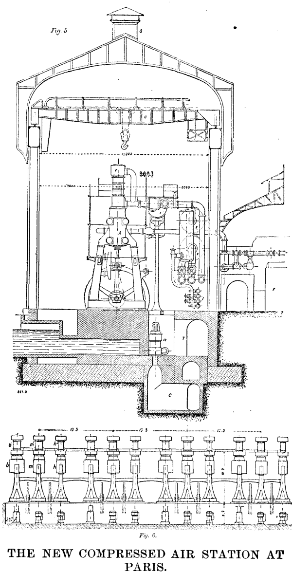
THE NEW COMPRESSED AIR STATION AT
PARIS. (FIG. 5, 6)
Moreover, according to Professor Riedler, the consumption of steam by the new Schneider engines will be only 5.3 kilos. per horse power and per hour as compared with some of the large engines requiring 9 kilos., and the Cockerill engines—using 8 kilos. per hour, not to speak of the older motors that are very extravagant in the use of steam. The St. Fargeau station is worked under a further disadvantage. The constantly increasing demand from subscribers taxes the resources of the station to their fullest extent, so that practically there is no reserve power.
In the new installation the work will be equally constant, but care will be taken always to have a sufficient reserve. Electric lighting will form a considerable part of the duty to be done from this station, and in all cases it is intended to work with accumulators, so that the resistance to be overcome by the engines, so far as this part of the duty is concerned, will be well known and uniform. The engineers of the Compressed Air Co., of Paris, have during the last five years acquired an experience which could only be attained at a high price and at the expense of a certain amount of failure; this period, it is claimed, is now passed, and in the new installation it is possible to put into practice all the valuable lessons learned at St. Fargeau, to say nothing of the more favorable natural conditions under which the extension is being started and the improvements in the compression of the air made by Mr. Popp and Professor Riedler, and to which we shall refer later.
Chiefly in consequence of the high value of the ground, vertical engines were adopted at the new station; the proximity to the river made the foundations somewhat costly, and the risk of occasional floods rendered it desirable to set the level of the engine bedplates 20 inches above the floor of the building; the foundations of the engines are continuous, but are quite independent of the building. There are three compressing cylinders in each set of engines, one being above each steam cylinder. Two of these are employed to compress the air to about 30 lb. per square inch, after which it passes into a receiver and is cooled; it is then admitted into the third or final compressing cylinder and raised to the working pressure at which it flows into the mains. In the illustrations, h, m, and b are the high, intermediate, and low pressure cylinders of one set of engines; as will be seen, each cylinder is on a separate frame connected by girders; directly above the cylinders are the two low and the one high pressure air cylinders, b¹, m¹, and h¹ respectively. The former deliver the air compressed to the first stage into the receiver, T¹ (see Fig. 5), whence it passes into the third compression cylinder, and thence by a main into the cylinders, R R, which are in direct communication with the delivery mains; these mains terminate in the subway, T. The water for condensation is brought into the engine house by the channel, C, and the condenser pumps, a, draw direct from this supply; the discharge main back to the river is shown at A. The relative positions of the engine and boiler houses are indicated in Figs. 2 to 5, where F shows the end of one group of boilers; the air supply for the compressors is led from the central raised portion, S, of the roof.
Professor Riedler's first experiments in improving the efficiency of air compressors were made with one of the Cockerill compressors in use at the St. Fargeau Station, and considerable difficulty attended this work, because the machinery was necessarily kept almost in constant operation. These compressors were designed by MM. Dubois and Francois, of Seraing. Two of their leading features were the delivery of the compressed air at as low a temperature as possible, and with a relatively high piston speed of about 400 ft. a minute. The former object is attained by the injection of a very fine water spray at each end of the air cylinder, and its rapid removal with each stroke; the free as well as the compressed air flows through the same passages, one at each end of the cylinder; the inlet valves being placed at the side of these passages, and the outlet or compressed air valves at the top, the compressed air, entering a chamber above the cylinder, common to both valves, and passing thence to the reservoir. The compressed air valves, which are seven in. in diameter, are brought back sharply to their seats at each stroke, by a small piston operated by compressed air flowing through a by-pass from the chamber. The illustrations published by us on page 686 of our forty-seventh volume show the construction of these compressors. The engravings on page 683 of the same volume illustrate the compressors used in a somewhat older part of the installation; they were made by M. Blanchod, of Vevey, and a passing reference may be made to them. The air is admitted through valves in the cylinder, and is forced out through spring-loaded valves; water is admitted into the cylinder to cool the air.
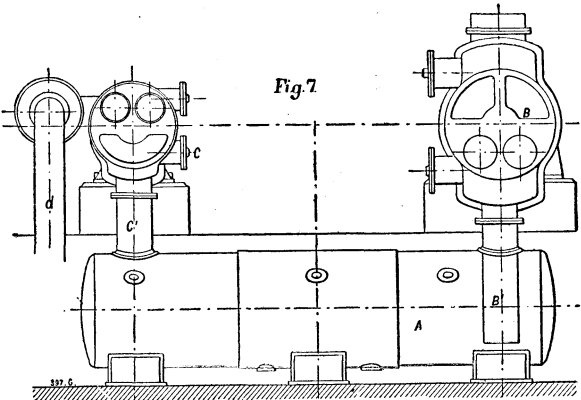
Fig. 7 indicates the modification made by Professor Riedler in one of the Cockerill compressors: a receiver, A, was placed under the two compressing cylinders, B and C. The first stage is completed in the large cylinder, B, the air being compressed to about 30 lb. per square inch; from this it is discharged into the receiver, A, through the pipe, B¹, where it meets with a spray injection that cools it to the temperature of the water. The final stage is then effected in the smaller cylinder, C, which, drawing the air from the receiver through the pipe, C¹, compresses it to about 90 lb. and delivers it through the pipe, d, to the mains. We hope shortly to publish drawings of this compressor in its final form; in its elementary stage Professor Riedler claims to have obtained some very remarkable results. He says that the waste spaces in his modification were much smaller than in the Cockerill compressor, while the efficiency of the apparatus was largely increased. The actual engine duty per horse power and per hour was raised, as a maximum, to 384 cubic feet of air at atmospheric pressure, and compressed to 90 lb. per square inch, a marked increase on the duty of the compressors in use at the St. Fargeau station. The Cockerill compressors experimented on at the same time showed a maximum duty of 306 cubic feet of air. A considerable advantage is claimed in drawing clean and cool air from the outside of the building, and beyond the main feature of carrying out the compression in two stages, Mr. Riedler appears to have shown great skill in introducing several minor alterations and improvements in the plant.
 Figs. 8, 9 and 10 are diagrams showing the comparative
efficiency of the three types of compressors at St.
Fargeau—Fig. 10 being a diagram of the Riedler
compressor—and indicate the gain derived from the
intermediate cooling. The loss is shown to be only 12 per
cent., as compared with a loss of 43 per cent. in a large
part of the plant, and of 105 per cent. in the earlier
compressors of the St. Gothard type. The table
given herewith contains a summary of trials made
by Professor Gutermuth, and are intended to show
the comparative results of an extended trial with three
kinds of compressors at St. Fargeau.
Figs. 8, 9 and 10 are diagrams showing the comparative
efficiency of the three types of compressors at St.
Fargeau—Fig. 10 being a diagram of the Riedler
compressor—and indicate the gain derived from the
intermediate cooling. The loss is shown to be only 12 per
cent., as compared with a loss of 43 per cent. in a large
part of the plant, and of 105 per cent. in the earlier
compressors of the St. Gothard type. The table
given herewith contains a summary of trials made
by Professor Gutermuth, and are intended to show
the comparative results of an extended trial with three
kinds of compressors at St. Fargeau.
  PERFORMANCES OF COMPRESSORS AT THE ST. FARGEAU CENTRAL STATION.

--------------+-------+--------+------+-------+--------+--------+----------+
              |       |        |      |       |        |        |          |
              |Revolu-| Horse- |      |Amount |Quantity| Cubic  |          |
Compressors.  | tions | Power  |Effic-|of Air | of Air |Feet of |Final Air |
              |of Eng-|Absorbed|iency.|Passing| Passing|Air per |Pressure. |
              |ine per|   by   |      |through| through| Horse- |          |
              |Minute.|Compres-|      | Inlet | Valves | Power  |          |
              |       | sors.  |      | Valves| per    | and per|          |
              |       |        |      | each  | Hour.  |  Hour. |          |
              |       |        |      |Revolu-|        |        |          |
              |       |        |      | tion. |        |        |          |
--------------+-------+--------+------+-------+--------+--------+----------+
              |       |        |      | cubic |  cubic |        |lb. per   |
1.            |       |        |      | feet  |  feet  |        |sq. in.   |
Sturgeon      |       |        |      |       |        |        |          |
Compressor    |  37   |   302  | .87  | 41.67 |  91,507| 261.3  | 90       |
Diameter of   |  37   |   258  | .87  | 38.13 |  84,650| 276.1  | 90       |
cylinder,     |       |        |      |       |        |        |          |
23.62 in.     |       |        |      |       |        |        |          |
and 21.66 in.;|       |        |      |       |        |        |          |
stroke,       |       |        |      |       |        |        |          |
48.63 in.     |       |        |      |       |        |        |          |
              |       |        |      |       |        |        |          |
2.            |       |        |      |       |        |        |          |
Cockerill     | 40    |   337  | .83  | 46.61 | 111,864| 281.83 | 90       |
Compressor.   | 45    |   353  | .83  | 46.61 | 125,844| 302.66 | 90       |
Diameter of   | 40    |   342  | .88  | 49.43 | 118,632| 296.65 | 90       |
cylinder,     | 46    |   377  | .85  | 48.02 | 132,534| 298.77 | 90       |
25.98 in.;    | 38.67 |   324  | .89  | 50.14 | 116,434| 306.19 | 90       |
stroke,       | 38.5  |   337  | .89  | 50.14 | 115,818| 294.18 | 90       |
47.24 in.     | 38.6  |   329  | .91  | 50.84 | 117,740| 305.13 | 90       |
              |       |        |      |       |        |        |          |
              |       |        |      |       |        |        |          |
3.            |       |        |      |       |        |        |          |
Riedler       | 52    |   615  | .985 | 77.34 | 241,300| 353.50 | 90       |
Compressor.   | 60    |   709  | .985 | 76.98 | 277,128| 353.50 | 90       |
Diameter of   | 38    |   422  | .985 | 77.34 | 176,330| 376.12 | 90       |
low-pressure  | 39    |   424  | .985 | 77.34 | 181,030| 384.60 | 90       |
cylinder,     |       |        |      |       |        |        |          |
42.91 in.;    |       |        |      |       |        |        |          |
diameter of   |       |        |      |       |        |        |          |
high-pressure |       |        |      |       |        |        |          |
cylinder,     |       |        |      |       |        |        |          |
26.38 in.;    |       |        |      |       |        |        |          |
stroke,       |       |        |      |       |        |        |          |
47.24 in.     |       |        |      |       |        |        |          |
--------------+-------+--------+------+-------+--------+--------+----------+
The results thus obtained were so satisfactory that the designs were prepared for the great compressors to be operated at the new central station on the Quai de la Gare by the 2,000 horse power engines.
The transmission of the compressed air through the mains is unavoidably attended with a certain percentage of loss, which, of course, increases with the length of the transmission, the presence of leakage at the joints, etc. Professor Riedler has devoted considerable time to the investigation of this source of waste, and we shall presently refer to the results he has recorded; in the first place, however, we propose to consider what he has to say on the subject of utilizing the air at the points of delivery, and the means employed for obtaining a relatively high efficiency of the motor.
In the earliest stages of the Popp system in Paris it was recognized that no good results could be obtained if the air were allowed to expand direct into the motor; not only did the formation of ice due to the expansion of the air rapidly accumulate and choke the exhaust, but the percentage of useful work obtained, compared with that put into the air at the central station, was so small as to render commercial results hopeless. The practice of heating the air before admitting it to the motor is quite old, but until a few years ago it never seems to have been properly carried out; in several mining installations where this motive power had been long used, more or less imperfect attempts had been made to heat the air; in one instance only, recorded by Professor Riedler, was an efficient means employed. In this case a spray of boiling water was injected into the cylinder and mixed with the air at each stroke, with the result that a very marked economy was obtained.
After a number of experiments, Mr. Popp arrived at the conclusion that the simplest mode of heating, if not the most efficient, was at all events the most suitable, as it was a matter of the first importance that subscribers should not be troubled with the charge of any apparatus involving complication or careful management; he therefore adopted a simple form of cast iron stove lined with fireclay, heated either by a gas jet or by a small coke fire. It was found that this apparatus, crude as it was, answered the desired purpose, until some better arrangement was perfected, and the type was accordingly adopted throughout the whole system. It was quite recognized that this method still left much to be desired, and the economy resulting from the use of an improved form was very marked.
From a large number of trials very carefully carried out by Professor Gutermuth, it was found that more than 70 per cent. of the total number of calories in the fuel employed was absorbed by the air and transformed into useful work. Whether gas or coal be employed as the fuel, the amount required is so small as to be scarcely worth consideration; according to the experiments carried out, it does not exceed 0.09 kilo. per horse power and per hour, but it is scarcely to be expected that in regular practice this quantity is not largely exceeded. Professor Weyrauch has also carefully investigated this part of the subject and fully confirms, if he, indeed, does not go beyond Professor Gutermuth. He claims that the efficiency of fuel consumed in this way is six times greater than when burnt under a boiler to generate steam. He goes so far as to assert that with a good method of heating the air, not only can all the losses due to the production and the transmission of the compressed air be made good, but also that it will actually contain more useful energy at the motor than was expended at the central station in compressing it.
According to Professor Riedler, from 15 to 20 per cent. above the power at the central station can be obtained by means at the disposal of the power users, and it has been shown by experiment that by heating the air to 250 deg. Cent. an increased efficiency of 30 per cent. can be obtained. Better results than those heretofore obtained may, therefore, be confidently expected with a more perfect and economical application of the fuel in heating the air, and a better means of regulation in admitting it to the motors. In his report Professor Riedler indicates a method by the use of which he considers considerable advantages may be secured. This is the heating the air in two stages instead of at one operation, and passing it through two motors, to the first of which the air is admitted heated only to a moderate extent; the exhaust from this motor then passes into a second heater and thence into the second motor. A series of experiments with this arrangement were recently carried out.
The consumption of air per brake horse power was reduced from 812 cubic feet per hour, a favorable duty in the single motor, to 720, and in the best result to 646 cubic feet with the two motors and double heaters. It should be added that these trials were carried out with steam engines but ill adapted for the purpose. It is to be regretted that the experiments of Professor Riedler could not have been conducted with more perfect appliances, but it must be borne in mind that the utilization of compressed air, especially as regards the motors, is still in a very imperfect stage, and that a great deal remains to be done before the maximum power available at the motor can be obtained. Investigations in this direction for a considerable time to come must be directed, therefore, toward improving the design and construction of the motors and the treatment of the air at the point of delivery into the engine.
A large number of motors in use among the subscribers to the Compressed Air Company, of Paris, are rotary engines developing one horse power and less, and these in the early times of the industry were extravagant in their consumption, to a very high degree. To some extent this condition of things has been improved, chiefly by the addition of better regulating valves to control the air admission.
As altered, the two horse power rotary motors, when employed as cold air engines, a method often desired in special industries, consume 1,059 cubic feet per hour and per indicated horse power; with a moderate degree of heating, say to 50 deg. Cent., this consumption falls to 847 cubic feet. The efficiency of this type of rotary motors with air heated to 50 deg. may now be assumed at 43 per cent., not a very economical result, it is true, and one that may be largely improved, yet it is evident that with such an efficiency the use of small motors in many industries becomes possible, while in cases where it is necessary to have a constant supply of cold air, economy ceases to be a matter of the first importance.
Some useful results were obtained with compressed air used in crank engines; it is to be regretted that with this, also, apologies have to be made for the imperfect design and construction; they were old steam engines, some of those of two horse power losing from 25 to 30 per cent. by their own friction; some of the others tried, however, were far better, a newer type losing only from 8 to 10 per cent., while the 80 horse power referred to below showed an efficiency of 91 per cent. From these trials Prof. Riedler deduces—assuming 85 per cent. efficiency—a consumption of 611, 752, and 720 cubic feet per brake horse power. It is very evident from the foregoing that the Compressed Air Company, of Paris, will never do itself justice until as much thought and care has been devoted to the economical use of the motive power as has been expended in the means of producing it, and Professor Riedler's recent investigations should be especially useful in this respect. The question has indeed attracted the attention of more than one manufacturer, and reference is made to a particular type of small rotary motors which are being constructed by MM. Riedinger & Co., and which is stated have given very excellent results. These engines were specially used for working sewing machines and developed on the brake an efficiency of 34.07 and 51.63 foot pounds per second. Trials were made with a half horse power variable expansion Riedinger engine.
     TRIALS OF A SMALL ROTARY RIEDINGER ENGINE.
 ______________________________________________________________
                                               |       |
  Number of trials.                            |   I.  |   II.
 ______________________________________________|_______|_______
                                               |       |
 Initial air pressure.     lb. per square inch |    86 | 71.8
      "      temperature.           deg. Cent. |   +12 |  +170
 Ft. pounds per second  measured on the brake. | 51.63 | 34.07
 Revolutions per minute.                       |   384 |  300
 Consumption of air for one horse power per    |       |
    hour.                                      | 1,377 |  988
 ______________________________________________|_______|_______


     TRIALS OF A 0.5 HORSE POWER RIEDINGER ROTARY ENGINE.
 _____________________________________________________________________
                                           |      |      |      |
  Number of trials.                        |  I.  |  II. | III. |  IV.
 __________________________________________|______|______|______|_____
                                           |      |      |      |
 Initial pressure of air.  lb. per sq. in. |   54 | 69.7 |   85 | 71.8
      "  temperature of air.    deg. Cent. |  170 |  180 |  198 |    8
 Final        "        "            "      |   25 |   20 |  ... |   25
 Revolutions per minute.                   |  335 |  350 |  310 |  243
 Foot pounds per second measured on        |      |      |      |
    brake.                                 |  271 |  477 |  376 |  316
 Consumption of air per horse power        |      |      |      |
    and per hour.                          |  883 |  791 |  900 |1,148
 __________________________________________|______|______|______|_____


    TRIAL OF AN 80 HORSE POWER (NOMINAL) FARCOT STEAM ENGINE.
 ______________________________________________________________
                  |      |      |             |
                  | Re-  | In-  |             | Consumption of
                  | vo-  | di-  | Temperature |  air per horse
                  | lu-  | ca-  |    of air.  |  power and per
                  |tions | ted  |             |      hour.
                  |      |      |_____________|________________
                  | per  |horse |      |      |       |
    Motor.        |      |      |Admis-| Ex-  |Nominal| Brake
                  | min- |power.| sion.|haust.| horse | horse
                  | ute. |      |      |      | power.| power.
 _________________|______|______|______|______|_______|________
                  |      |      |deg. C|deg. C|       |
 Nominal 80 horse | 54.3 | 72.3 |  129 |  21  |  469  |  517
 power single cy- | 54.3 | 72.3 |  152 |  29  |  437  |  475
 linder Farcot    | 54.0 | 72.3 |  160 |  35  |  424  |  465
 engine.          | 40   | 65.0 |  170 |  49  |  438  |  477
 _________________|______|______|______|______|_______|______________
These motors, it may be assumed, represent the best practice that has been obtained up to the present time in the construction of compressed air motors; with the smallest of them, indicating about one-tenth of a horse power, the consumption of air, when admitted cold, was 1377 cubic feet and 988 cubic feet when the air was heated before admission. The half horse power engine consumed 1148 cubic feet of cold air, and of heated air 791 cubic feet per horse power and per hour. It should be mentioned that these, the most valuable and suggestive of all the trials carried out by Professor Riedler, were conducted with the greatest care, two distinct modes of measuring the air supplied being followed on two occasions for each test; it may therefore be considered that the results given are absolutely correct. The trials were made with an old single cylinder Farcot engine, nominally of 80 horse power, but indicating over 72.3. With this engine the consumption of air varied from 465 to 517 cubic feet, the larger consumption being due to the lower temperature (129 deg. Cent.) to which the air was raised before admission; in the most economical result the temperature was 160 deg. Cent. The volumes of air referred to are, of course, in all cases taken at atmospheric pressure.
Among the important losses that have to be reckoned with in every system of distributing motive power from a central station—whether by steam or by electricity, water, or compressed air—losses must occur in the mains by which the power generated is transferred from the point of production to that of consumption. In the case we are now considering very careful tests were conducted in 1889 by Professor Kennedy, to whose report we have already referred. Since that time important changes have been made by the Compressed Air Company, at Paris, in the details of distribution, and on this account the later investigations of Professor Riedler on the losses due to this cause are of special interest.
Before its admission into the mains a certain loss occurs at the St. Fargeau station, in the large reservoirs to which the air is delivered from the compressors. This question of preliminary storage was one that received considerable attention when the designs of the new station on the Quai de la Gare were being considered. It was intended to construct very large receivers in the basement of the station, and the foundations for these were even commenced. It was decided, however, that for the 10,000 horse power which is to form the first section of the new station, and for which the complete system of mains has already been laid down, storage reservoirs would be unnecessary, and a saving both in first cost and subsequent loss of air would be effected. The length of mains of 19.69 in. diameter is so considerable that they will contain at all times a sufficient reserve of air to prevent any irregularities in pressure at the motors.
With reference to these mains it may be mentioned that, unlike the 11.81 in. conductors of the St. Fargeau system, of which 17 kilometers are laid in the Paris subways, the new mains are entirely laid in the streets, it having been found impossible to make room for these large pipes in the subways already crowded with telegraph and telephone wires, water mains, etc.
Professor Riedler investigated the two causes of loss in the mains—leakage and resistance. It was superficially evident that the mains of the old system were so well laid, and the joints so well designed, that the loss from leakage was never a serious one. In order, however, to ascertain the amount accurately, a series of careful experiments were carried out by Professor Gutermuth with the 11.81 in. mains of the St. Fargeau system.
These trials refer to the mains running from the St.
     EXPERIMENTS ON LEAKAGE IN MAINS.

---------------------------------------------------------------------
| |                 |         |               |             | L P A |
| |                 |         | Air Pressure  |   Loss of   | o e i |
| |                 |         |  in Mains.    |  Pressure.  | s r r |
| |                 |         |---------------|-------------| s     |
| |                 |         |       |       |      |      |   C D |
| |System of Mains  | Length. |       |       |      |      | o e e |
|N|    Tried.       |         |  At   |  At   |      |      | f n l |
|u|                 |         |Begin- | End   |During| Per  |   t i |
|m|                 |         |ning of|  of   |Trials|Hour. | A . v |
|b|                 |         |Trials.|Trials.|      |      | i   e |
|e|                 |         |       |       |      |      | r o r |
|r|                 |         |       |       |      |      |   f e |
| |                 |         |       |       |      |      |     d |
--+-----------------+---------+-------+-------+------+------+-------|
| |                 | yards.  | atm.  |  atm. |      |      |       |
|1|Southern reseau  |         |       |       |      |      |       |
| | to Place de la  |         |       |       |      |      |       |
| | Concorde.       |  9,980  | 6.5   |  6.0  | 0.5  | 1.5  |  3    |
|2| Total reseau    | 18,500  | 6.9   |  5.9  | 1.0  | 1.5  |  6.3  |
|3|To Place de      |         |       |       |      |      |       |
| | la Concorde     |  9,980  | 7.0   |  6.43 | 0.57 | 0.75 |  2.16 |
|4|Total reseau     | 18,500  | 6.7   |  5.28 | 0.88 | 1.32 |  5.5  |
|5|Northern reseau  |         |       |       |      |      |       |
| | to Rue de Belle-|         |       |       |      |      |       |
| | ville.          |  1,530  | 6.0   |  5.0  | 1.0  | 0.6  |  2.3  |
|6|To the Rue des   |         |       |       |      |      |       |
| | Pyrenees.       |    600  | 6.1   |  3.7  | 2.4  | 0.56 |  2.2  |
---------------------------------------------------------------------
Fargeau station to the Place de la Concorde, a length of 9.142 kilometers; to the whole system of mains, 16.5 kilometers; to the northern mains running from St. Fargeau to the Rue de Belleville, 1.4 kilometers; and from St. Fargeau to the Rue des Pyrenees, 6.5 kilometers. It will be seen from the figures given in the table that the actual loss is small, and it is stated that this is due chiefly to the elastic joint employed throughout the system, excepting in the Rue de Belleville, where rigid couplings are used, and continual trouble is experienced from loss by leakage. In all cases the losses given are the maximum, which only occur under the most unfavorable conditions.
It was found, during the first, second, and fourth tests, that considerable leakage occurred between the St. Fargeau central station and the Rue de Belleville. During the trials two and four, an uncertain amount of loss occurred from the consumption of air required to work the pneumatic clocks, and also motors in the circuit, that could not be stopped. The tests two and four include all losses in the service pipes, as well as the mains.
The production of compressed air at the central station is assumed at 30,000 cubic feet per hour (atmospheric pressure), and in all cases the loss in the mains is taken as a percentage of the total production.
The losses due to resistance in the mains were also examined with great care, over independent sections, as well as through the complete réseau. During the early part of these trials, an unusual and excessive loss was recorded, the cause of which could not be at first ascertained. At intervals along these mains are placed a number of water reservoirs which receive the water injected into the mains; in addition to these the direct flow of the air is interrupted by numerous siphons, the stop valves to branches, etc. Investigation showed that the presence of these reservoirs created considerable resistance on account of an increased and subsequently reduced section. The exact loss from this cause was, therefore, carefully measured, as well as the losses existing in the mains not so interrupted. The results show that the loss by expansion at one reservoir, when the speed of the air flow was 23 ft. per second, was equal to 0.15 atmosphere; with a speed of 29 ft. 6 in. per second, it amounted to 0.2 atmosphere.
Therefore, the presence of five such reservoirs would cause a loss in pressure equal to one atmosphere. This very undesirable arrangement is not repeated in the new system, the sumphs being connected in such a way as not to modify the section of the tube, nor consequently the pressure of the air. The presence of the siphons and stop valves did not seem to affect the pressure to any measurable extent. The following table contains a list of the more important mains tested, and it may be mentioned that the resistance, due to the reservoirs, was at first partially included. The trials were carried out while the mains were not being drawn upon by subscribers.
-----------------------------------------------------------------------
                                                   |            |
Section of Mains Tested.                           |  Length.   |No. of
                                                   |            |Tests.
                                                   |            |
---------------------------------------------------+------------+------
                                                   |  yards.    |
From the central station to the end of reseau and  |            |
  back to central station by return circuit        |  18,100    |   7
From the central station to the Rue Fontaine au    |\ 14,600    |/  3
  Roi                                              |/  9,900    |\  4
From the central station to the Rue de la          |            |
  Charonne                                         |   9,490    |   5
From the Rue de la Charonne to Fontaine au         |            |
  Roi                                              |   4,770    |   3
From the central station to the Avenue de la       |            |
  Republique                                       |   1,860    |   8
Various trials on different lengths of mains       |770 to 8,000|  11
-----------------------------------------------------------------------
Over the whole system of 16.5 kilometers, which was also tested when no air was being taken off, there were four reservoirs of considerable size, and which offered a large resistance with a corresponding loss of pressure; on the line there were also 23 siphons and 42 stop valves.
These trials were repeated several times to secure accuracy, and the speed of the air was brought to 49 ft. a second. The results obtained in one of these trials may be taken as an example. The main between the Rue St. Fargeau and the Fontaine au Roi, on which there are no collecting reservoirs, but three siphons and eight stop valves, gave, with an average speed of 21 ft. 3 in., a loss in pressure of 0.05 atmosphere for each kilometer of main.
From these experiments it would appear that, assuming a speed of 21 ft. per second, a loss in pressure of one atmosphere would correspond to a distance of 20 kilometers; that is to say, a central station could extend its mains on all sides with a radius of 20 kilometers, and the motors at the ends of the lines would receive the air at a pressure 15 lb. less than at the central station. Professor Riedler states that as an actually measured result, the velocity of the air through the mains of the St. Fargeau system is 19 ft. 8 in. per second, and that the loss in pressure per kilometer is 0.07 atmosphere. From this it follows that including the resistances due to the four reservoirs, and other obstructions actually existing, an allowance of one atmosphere loss on a 14 kilometer radius is ample. By increasing the initial pressure of the air, much better results can be obtained, and future attention in practice should be devoted to this point. The amount of work required to compress air does not increase in the same ratio as the pressure, and for this reason considerable economy can be effected at the first stage, and the loss in the mains will be reduced.
Passing to another point of the same subject, Professor Riedler considers the best dimensions that should be given to the mains. Resistance decreases with an increase in the diameter of these and in direct ratio to their diameter; for this reason—still assuming a pressure corresponding to a velocity of 20 ft. per second—with a fall of one atmosphere, a length of 40 kilometers could be succesfully worked.
The mains of the new réseau for the Quai de la Gare station are 19.69 in. in diameter; they are built up of steel plates riveted, and this Professor Riedler considers to have been a serious error on account of the extra resistance offered by the large number of rivet heads.
The following may be taken as a brief summary of Professor Riedler's conclusions: Recent improvements in central station practice have resulted in an increased efficiency of about 30 per cent. in the compressors, but this benefit can only be realized when the new station is in operation. That the small and very imperfect air engines in use on the system give an efficiency of 50 per cent., while with ordinary steam engines driven by air an efficiency of 80 per cent. can be reached with a very small expenditure of fuel for heating the air before admitting it into the motor. That special attention should be given to the improvement of air engines, and that with increased initial pressures at the central station the distance of the transmission can be very considerably augmented. Finally, Professor Riedler claims that power can be transmitted by compressed air more conveniently and more economically than by any other means.
Papin, Worcester, Savery, were the authors of the period of application of the power of steam to useful work in our later days. The world was, in their time, just waking into a new life under the stimulus of a new freedom that, from the time of Shakespeare, of Newton, and of Gilbert, the physicist, has steadily become wider, higher, and more fruitful year by year. All the modern sciences and all the modern arts had their reawakening with the seventeenth century. Every aspect of freedom for humanity came into view in those days of a new birth. Both the possibility of the introduction of new sciences and of new arts and the power of utilizing all new intellectual and physical forces came together. The steam engine could not earlier have taken form, and, taking form, it could not have promoted the advance of civilization in the earlier centuries. The invention becoming possible of development and application, the promotion of the arts and of all forms of human activity became a possible consequence of its final successful introduction into the rude arts that it was to so effectively promote and improve.
But the work of these inventors was in itself but little more important than that of the Greek inventor of the steam ælopile, for each brought forward a machine which was, from a business point of view, utterly impracticable, and which, in each case, only served to show that a better device might prove useful and lead the way to its introduction. The merit of the inventors of the eighteenth century was that they were able to lead the way, to point out the path to success, to furnish evidence of the value of the coming, crowning invention. The "fire engines," as they were then called, of these now famous men were merely contrivances by the use of which the pressure of confined steam of high tension could be brought to act on the surface of a mass of confined water, forcing it downward into pipes through which it was led off and upward to a higher level; and thus a mine could be drained, ineffectively and expensively to be sure, but vastly more satisfactorily than by the animal power of the time. The machine of Savery was the best of all; but that was only a somewhat improved and manageable rearrangement of the engines of Papin and Worcester. And, after all, Papin, the greatest man of science perhaps of his time, died in poverty; Worcester languished in prison his whole life, and the later efforts of his widow brought nothing by way of a return for his invention; nor did either they or their successor, Morland, make the introduction of the engine either general or remunerative.
Savery, coming on the stage at more nearly the right time to seize upon an opportunity, gained more than either of his predecessors; but we have no evidence that he ever acquired any large compensation or met with any remarkable business success in the introduction of the rude engine which bore his name; nor did Desaguliers, the great philosopher, or even Smeaton, the great engineer, of the later years of that century, make any great success of it. It was reserved for Watt to reap the harvest. But, though he so effectively reaped where his predecessors had sown, Watt is not the greatest of the inventors of the steam engine, if we rate his standing by the magnitude of the improvement which marked his reconstruction of the engine.
It was NEWCOMEN who made the modern steam engine.
When Newcomen came forward the labors of Worcester in Great Britain had sufficed to attract the attention of all intelligent men to the character of the problem to be solved, and to convince them of its importance and promise. The work of Savery had shown the practicability of the solution of the problem, both in mechanics and finance. He succeeded, though under great disadvantages and comparatively inefficiently. Once the task had been performed, though ever so rudely, the rest came easily and promptly. The defects of the Savery system were at once recognized; its great wastes of heat and of steam were noted, and the fact that they were inherent in the system itself was perceived. A complete change of type of machine was obviously requisite; it was this which constituted the greatest invention in the whole history of the steam engine, from Hero's time to our own; and to Newcomen we owe more than to any other man who ever lived, the value of the invention itself being considered, and the importance of the services of its introducer being left out of consideration. No such complete and vital improvement and modification of the machine has ever been effected by any other man, Watt and Corliss not excepted. Newcomen and his comrade Calley—we do not know how the honors should be divided—produced the modern steam engine. Its predecessor, the Savery engine, had been a mere steam "squirt." Newcomen constructed an engine. Savery built a simple combination of cylindrical or ellipsoidal vessels which wastefully and at once performed all the several offices of engine, pump, condenser, and boiler; Newcomen divided the several elements among as many parts, each especially adapted to the performance of its task in the most effective manner—the condenser excepted; for that was Watt's principal invention—and thus produced the first steam engine in the modern sense of that term.
It was Newcomen, not Watt, who gave us the train of mechanism that we now call the steam engine. It is to Newcomen, rather than Watt, that we owe the highest honors as an inventor in this series of the most important of all the products of the inventive genius of mankind. Newcomen brought into existence a new, the modern, type of engine, and effected the greatest revolution that has been recorded in the history of the arts. Without Newcomen, there might have been no Watt; without Watt, there very possibly may not even yet have been brought into existence that giant of our time, whose mighty powers are employed more effectively than ever those of Aladdin's genii, in building palaces, in transporting men and material, in doing the work of the whole world; promoting the welfare of the race, in a single century, more than had all the forces of matter and mind together in the whole previous history of the world. Newcomen laid down a foundation beneath our whole economic system, out of sight, almost, but the essential base, nevertheless, on which Watt and his successors have carried up the great superstructure which seems to us to-day so imposing; which is so tremendous in magnitude, importance, and result. If to any one man could be assigned the credit, it is Newcomen who is to be considered the inventor of the steam engine.
James Watt, indisputably the great inventor that he was, found the steam engine ready to his hand, applied himself to its improvement, and made it substantially what it is to-day. His most important work, the most unique service performed by him, was, however, that of its adaptation and introduction to do the work of the world. James Watt was the inaugurator of the era of refinement of the machine already invented, and the greatest of its builders and distributors. His inventions were all directed to the improvement of its details, and his labors to its introduction and its application to the myriad tasks awaiting it. By the hands of Watt it was made to pump water, to spin, to weave, to drive every mill; and he it was who gave it the form demanded by Stephenson, by Fulton, by the whole industrial world, for use on railway and steamboat, and in mill and factory, throughout the civilized countries of the globe. It was this great mechanic who showed how it might be made to do its work with least expense, with highest efficiency, with greatest regularity, with utmost concentration of power.
The grand secret of his success was historical and economic, as much as scientific and mechanical. He brought out his inventions just when the world was economically and historically ready for them. The age of authority was past, that of freedom was come; the period of political and ecclesiastical tyranny was gone by, and that of the spontaneous development of man was arrived. The great invention was offered to a world ready and needing it, and, more than all, competent, for the first time in history, to make and use it.
James Watt was himself a product of the modern scientific spirit. He was a man so constituted mentally that he could apply scientific methods to problems which his logical and clairvoyant mind could readily and exactly formulate the instant he was led to their consideration in the natural course of his progress. He was the ideal great inventor and mechanic. With inventive genius he combined strong common sense—not always a quality distinguishing the inventor—clear perception, breadth of view, and scientific method and spirit in the treatment of every question. His natural talent was re-enforced by an experience and an environment which led him to develop these ways and this mental habit. His trade was that of an instrument maker, his position was that of custodian and repairer of the apparatus of Glasgow University. He had for his daily companions and stimulus the great men and ozonized atmosphere of that famous institution. He kept pace with advancing science, and was imbued, both naturally and through contact with its promoters, with that ambition and those aspirations which are the life element of all progress, whether scientific or other. He was aware of the nature of the problems seeking solution at the time, and familiar with the state of his own art and that of the great mechanicians about him. Everything was favorable to his progress, so soon as he should be given an opportunity to take a step in advance and to come into sight at the front. The man and the time were both ready, and all conditions, internal and external, social and personal, were favorable to his development.
The invention upon which Watt was to improve was at his hand. A word in regard to its status at the moment will throw some light upon that of Watt and his creation. Newcomen had, as we have seen, produced the modern type of steam engine as an original and wholly novel invention. But this machine, marvelous as an advance upon pre-existing forms of the steam engine, was still, as seen in the light of recent knowledge and experience, exceedingly defective. The purpose of a steam engine is to convert into usefully applicable power the hidden energy of fuel, stored ages ago in the earth, by transformation, through the action of vegetation, from the original form, the heat of the sun, into an available form for reconversion, through thermodynamic operations. In this process of reconversion, whatever the nature of the machine used in the operation, there are invariably wastes, both of heat required for conversion into power and of the power thus produced. That machine which effects the most complete transmutation of the heat supplied it into mechanical power, which wastes the least amount of heat supplied and of power produced, is the best engine, and constitutes an advance over every other.
It was this reduction of wastes that made the Newcomen engine so much superior to that of Savery. The latter was by far the simpler and less costly construction; but its enormous losses, both of heat and of power, mainly the former, however, made it an extravagant expenditure of money to buy and use it. The Newcomen engine, costly and cumbrous, comparatively, nevertheless wasted so much less heat and steam and fuel that no one could afford to buy the cheaper machine. Before considering what Watt accomplished, we may find it profitable to examine into the nature of the wastes which characterized this later and better machine on which he effected his improvements.
The Newcomen engine consisted of a steam boiler, a steam cylinder, a beam and a set of pumps. By making the boiler do its work separately, the engine acting independently, and the pumps as a detached portion of the mechanism, this inventor had reduced to an enormous extent those wastes of heat and of steam and of fuel which were unavoidable in the older machines in which all these parts were represented by a single vessel, or by two at most, in each element. In the Savery engine, the steam entering first heated up the interior of the working vessel to its own temperature, and held it at that temperature in spite of the cooling influence of the water present. This consumed large quantities of heat. It then was compelled to surrender probably much greater quantities still to the water itself, coming in direct contact as it did with its surface. If the water was agitated, either by the currents produced during its ingress or by the impact of the steam entering the vessel, this heating action penetrated to considerable depths and perhaps even warmed the whole mass very far above its initial temperature. This constituted another and a very serious loss. Then, again, as the water was gradually driven out of the containing vessel by the steam pressing on its surface, new portions of the vessel and new masses of water were continually brought in contact with the hot steam, taking its full temperature, and thus, often, probably, finally heating the whole mass of the forcing vessel, and a large proportion of the water as well, up to the temperature, approximately at least, of the steam itself. Thus in many instances, if not always, vastly more heat and steam were wasted, in this undesirable heating of water and forcing vessel, than were usefully employed in the legitimate work of raising the water to a higher level. In fact, in some cases in which these quantities were measured, the wastes were one hundred times as much as the work done. One per cent. of the heat supplied did the work; while ninety-nine per cent. was thrown away. One dollar or one shilling expended for fuel to do the work was accompanied by an expenditure of ninety-nine dollars or shillings thrown away, because of the imperfections of the system and machine. The whole history of the development of the steam engine has been one of gradual reduction of these wastes; until to-day, our best engines only compel us to spend five dollars for wastes to each dollar paid out for useful work. A business man would think that amply extravagant, however, and the man of science is continually seeking methods of evading these losses, a large proportion of which are now apparently unavoidable in heat engines, by finding some new system of heat and energy transformation.
Watt was the instrument maker and repairer at Glasgow University in the year 1763. His companions were, among others, the professors of natural philosophy and of mathematics in the university. Their conversation and their frequent presentation of practical and scientific questions and problems stimulated his naturally inquiring and inventive mind to the pursuit of a thousand interesting and promising schemes for the improvement of existing methods and machinery. Dr. Robison, then a student, suggested the invention of a steam carriage for use on common roads, and the young mechanician at once began experiments that, resulting in nothing at the time, were nevertheless continued, in one or another form, until all modern applications of steam came into view. Dr. Black taught Watt chemistry, then a newly constructed science, and led him on to the discovery, finally made by them independently, of the fact and the magnitude of the latent heat of steam; the discovery coming of a series of scientifically planned and accurately conducted investigations, such as the man of science of to-day would deem creditable. The treatises of Desaguliers and others on physics gave Watt a knowledge of that domain of natural phenomena which stood him in good stead later, when he attempted to apply its principles to the reduction of the wastes of the steam engine.
It was while at Glasgow University, working under such influences and in such an atmosphere of intellectual activity, that the accident of the Newcomen model engine needing repair brought to the mind of Watt the opportunity which, availed of at once, made him famous and gave the world its greatest aid, its most powerful servant. The observing mind of the great mechanic immediately noted its defects, sought their causes, found their remedy. He discovered, at once, that the quantity of steam entering the cylinder of the little engine has four times the volume of the cylinder receiving it: in other words, three-fourths of that steam must be condensed immediately on entrance. This meant, evidently, that only one-fourth of the steam supplied was utilized, and even then inefficiently, in doing its work. The reason of this was as easily seen, immediately the fact was revealed. As Watt himself expressed it, the causes of this loss, causes which would obviously be exaggerated in a small engine, were: "First, the dissipation of heat by the cylinder itself, which was of brass and both a good conductor and a good radiator. Secondly, the loss of heat consequent upon the necessity of cooling down the cylinder at every stroke in producing the vacuum. Thirdly, the loss of power due to the pressure of vapor beneath the piston, which was a consequence of the imperfect method of condensation." This much determined, the next step looked toward the confirmation of his conclusions and the remedy of the defects.
To meet the first difficulty he made a cylinder of wood, soaked in oil and baked, a non-conducting and non-radiating material. Then he was able to determine with some accuracy the quantities of steam and injection water used in the engine; and a comparison with the original cylinder and its operation showed that not only four times the quantity of steam, but also four times the amount of injection water was used as was necessary, assuming wastes checked. Further scientific research on the part of Watt gave him measures of specific heats of the metals and of wood, the specific volumes of steam at various working pressures, the evaporative efficiency of boilers, the pressures and temperatures of steam in the boiler under specified conditions, the quantities of steam and of water required for the operation of his little condensing engine.
Then came his enunciation of the grand principle of economy in the construction and operation of the steam engine: "Keep the cylinder as hot as the steam which enters it," as he expressed it. This was Watt's guiding principle, as it has been that of all his successors in the improvement of the economic performance of the steam engine and of all other heat engines. The great source of waste is the dispersion of heat, uselessly, which should be applied to the production of work by its transformation, thermodynamically, into the latter form of energy. The second form of waste is that of power thus produced in the unprofitable work of moving the parts of the engine itself; and the third is that of heat by transfer, without transformation, by conduction and radiation to surrounding bodies. In modern engines, the latter is but three or five per cent., in the best cases; the second waste constitutes perhaps ten per cent.; while the first of these losses amounts very usually to seventy per cent., of which last one-third or one-fourth is of the kind discovered by Watt, the rest being the thermodynamic waste incident to all known methods of operation of heat engines, and apparently unavoidable. In our very best and largest engines, the waste found by Watt to constitute three fourths of all heat supplied has been brought down to ten per cent., a fact which well exemplifies the advances made since his time of apprenticeship by himself and his successors of this nineteenth century. The steam engine of to-day, in its most successful operation, gives us twenty-five times as much power from a pound of coal as did the engine that the great inventor sought to improve: this is the magnificent fruit of that one discovery of James Watt, and of application of the simple principle which he so concisely and clearly stated.
The method adopted by Watt to secure a remedy, so far as practicable, of this defect of the older machine was as simple and as perfect as was the principle which it embodied. He first removed from the cylinder the prime source of its wastes; providing a separate condenser, and thus avoiding the repeated chilling of its surfaces by the cold water used in condensing the steam at exhaust, and also permitting its strokes to be made with far greater frequency, thus giving less time for cooling by the influence of the remaining vapors after condensation. He next went still further, and provided the cylinder with a closed top, keeping out the air, and a "jacket" of hot boiler steam to keep it as hot as the steam which entered it. These were the two great improvements which converted the first real steam engine into an economical form of heat engine and essentially finished the work so grandly begun by Newcomen and Calley. These changes gave us the modern steam engine; and these are Watt's first and greatest, but by no means only, contributions to the production of the modern world with all its comforts, its luxuries and its opportunities for material, intellectual and moral advancement of individual and of race. His work was to this extent complete in 1765.
But Watt did not stop here. There still remained for him the no less important and the, in some senses, still more imposing, work of finding employment for the new servant of mankind and of setting it at its work of giving the human arm a thousand times greater strength, to the mind of man uncounted opportunities to promote the advancement of knowledge, of civilization, of every good of the race. His was still the task of adapting the new machine to all the purposes of modern industry. It had been hitherto confined to the task of raising water from the depths of the mine; it was now to be harnessed to the railway train; to be made to drive the machinery of the mill, to apply its marvelous power to the impulsion of the river boat and ocean steamer; to furnish energy, through endless systems of transfer and use, to every kind of work that man could devise and should invent. All this meant the giving of the machine forms as various as the purposes to which it was to be devoted. It had previously only raised and depressed a rod; it must now turn a shaft. It had then only operated a pump; it must now turn a mill, grind our grain, spin our threads, weave our cloths, drive our shops and factories, supply the powerful blast of the iron furnace. It must be made to move with the utmost conceivable regularity, and must, with all this, do its work in the development of the hidden energy of the fuel, with the greatest possible economy, through the expansion of its steam. All this was achieved by James Watt.
The invention of the double-acting engine, in which the impulsion of the steam is felt both in driving the piston forward and in forcing it backward, both upward and downward, the application of its force through crank and fly wheel, the creation of an automatic system of governing its speed, and the discovery of the economy due to its complete expansion, were all improvements of the first magnitude, and of the greatest practical importance; and all these were in rapid succession brought into existence by the creative mind that had apparently been brought into the world for the express purpose of giving to the hand of man this mighty agent, to perfect the mightiest power that mind of man has yet conceived.
But to do the rest required more than inventive genius and mechanical skill. It demanded capital and the stored energy of labor and genius in other fields, directed by the mind of a great "captain of industry." This came to Watt through Matthew Boulton, a manufacturer of Birmingham, whose father and ancestors had gradually and toilsomely, as always, accumulated the property needed for the prosecution of a great business. The combination of genius and capital is always an essential to success in such cases; and good fortune, a Providence, we may well say, brought together the genius and the capitalist to do their work, hand in hand, of providing the world with the steam engine. Hand in hand they worked, and all the world to-day, and the race throughout its future life, must testify gratitude for the inexpressible obligations under which these two men have placed them, doing the work of the world.
Boulton & Watt, the capitalist with the inventor, gave the world the steam engine, finally, in such form and in such numbers that its permanent establishment as the servant of man was insured. The capitalist was as essential an element of success as was the inventor, and, in this instance, as in a thousand others, the race is indebted to that much-abused friend of the race, the capitalist, for much that it enjoys of all that it desires. The industry and patience, the skill and the wisdom required for the accumulation of this energy stored for future use in great enterprises is as important, as essential, as inventive power or any other form of genius. Talent and genius must always aid each other. This firm was established in 1764 and its main resources, aside from the bank account, were Watt's patent, about expiring, and Watt's genius, and Boulton's talent as a man of business. The patent was extended for twenty-four years, the new inventions of Watt, now beginning to pour from his prolific brain in a wonderful stream, were also patented, and the whole works were soon employed upon the construction of engines for which numerous orders soon began to pour in upon the now prosperous builders. The patent law established Boulton and Watt and the firm paid back the nation with handsome usury, giving it unimaginable profits indirectly through its control of the work of the world and large profits directly through the business brought them from all parts of the then civilized globe. There has never, in the history of the world, been a more impressive illustration of the value to a nation of that generous public policy, that simply just legislation, which gives to the man of brain control of the products of his mind. For a hundred years, Great Britain has, largely through her encouragement of the inventor and her protection of his mental property by securing the fruits of his labors, in fair portion, to him, gained the power of dictating to the world and has gained an advance that cannot be measured. Watt and Arkwright and Stephenson and Crompton and their ilk, protected by their government and its patent laws, made their country the peaceful conqueror of the world. The story of the work of the inventor is a poem of mighty meaning and of wonderful deeds. The inventor proved himself a mightier magician than ever the world had seen.
"A creature he called to wait on his will,
Half iron, half vapor—a dread to behold;
Which evermore panted, and evermore rolled,
And uttered his words a millionfold."
Such was the outcome of this grand modern "trust," a combination of the wisest legislation, the most brilliant invention, and the most wisely applied capital. There are "trusts" of which the outcome is most beneficent.
Since the days of Watt, the improvement of the steam engine and the work of inventors has been confined to matters of detail. All the fundamental principles were developed by Watt and his predecessors and contemporaries and it only was left to his successors to find the best ways of carrying them into effect. But these matters of detail have been found to involve opportunities to make enormous strides in the direction of securing improved efficiency of the machine. The further application of the principle which led Watt to his greatest inventions; of the principle, keep the cylinder as hot as the steam which enters it, of that which he enunciated relative to the advantage of expanding steam, and of that affecting the regulation of the machine; have reduced the costs of steam and of fuel to a small fraction of their earlier magnitude. One ton of engine to-day does the work of eight or ten in the time of Watt: one pound of fuel or of steam gives to-day ten times the power then obtained from it. A steamship now crosses the Atlantic in one-eighth the time required by the famous "liner" of the "Black Ball Line." The wastes of the engine have been brought down from above eighty per cent. to eight; and a half-ounce of fuel on board ship will now transport a ton of cargo over a mile of ocean.
FREDERICK E. SICKELS gave us the first practicable form of expansion gear in 1841; GEORGE H. CORLISS gave a new type of engine of marvelous perfection and economy in 1849; Noble T. Green, Wm. Wright and many less well known but no less meritorious inventors have since done their part in the transformation of the old engine of Watt into the modern wonder of concentrated and economical power, and marvel of accurate and beautiful design and workmanship. The "trip cut-off," with reduced clearances, increased boiler pressure, higher rates of expansion, accelerated speeds of engine, better construction in all respects, as well as improved design, have enabled us to avail ourselves to the utmost of the principles of Watt, and our mills, our railways, our steamers and our fields, even, have gained almost as extraordinarily by these advances, since the days of the great inventor, as through his immediate labors.
With the introduction of the new form of older energy, electricity, with the reduction of the lightning into thraldom, has now come a new impulse affecting all the industries. Through its mysterious, its still unknown action, steam now reaches out far from its own place, driving the electric car along miles of rail; giving light throughout all the country about it, turning night into day, and repressing crime while encouraging legitimate labor, reaching into distant chambers and every little workshop, to offer its powerful aid in all the distributed work of cities. Without the steam engine there would be little work available for electricity, but the appearance of this, the latest and most useful handmaid of steam, has given the engine work to do in an uncounted number of new fields, has called in the inventor once more to adapt steam to its new work. The "high-speed engine" is the latest form of the universal helper. And such has been the readiness and the intelligence of the contemporary inventor that we now have engines capable of turning their shafts three hundred rotations a minute and without a perceptible variation of velocity, whatever the change of load or the suddenness with which it is varied. In the days of Watt a fluctuation of five per cent. in speed was thought wonderfully small; in those of Corliss, the variation was restricted to two per cent. and we wondered at this unanticipated success. To-day, thanks to Porter and Allen, to Hartnell, to Hoadley, to Sims, to Thomson, to Sweet, to Ide, and to Ball, we have seen the speed fluctuation restricted to even less than one per cent. of its normal average.
The inventors of the steam engine are, through their representatives of to-day, according to the statisticians, doing the equivalent of twelve times the work of a horse, for every man, woman and child on the globe. We have not less, probably, than a half million of miles of railway, transporting something over 150,000,000,000 of tons a mile a year. A horse is reckoned to haul a ton weight about six and a half miles, day by day, by the year together. In the United States, it is reckoned that the steam engine, on the railways alone, hauls a thousand tons one mile, for every inhabitant of the country, every year, or, if it is preferred to so state it, a ton a thousand miles. This is the way in which the East and the West are, by the inventors of the steam engine, enabled to help each other. This costs about $10 each individual; it would require some 25 millions of horses to do the work, and would cost about $1,000 a family, which is more than twice the average family earnings.
Dr. Strong, in that remarkable book, "Our Country," says: "One man, by the aid of steam, is able to do the work which required two hundred and fifty men at the beginning of the century. The machinery of Massachusetts alone represents the labor of more than 100,000,000 men, as if one-half of all the workmen of the globe had engaged in her service." And again: "Some thirty years ago, the power of machinery in the mills of Great Britain was estimated to be equal to 600,000,000 men, or more than all the adults, male and female, of all mankind." Mr. Gladstone estimated that the aggregation of wealth on the globe during the whole period from the birth of Christ to that of Watt was equaled by the production in twenty years, at the middle of this century, with the aid of machinery driven by the fruit of the brain of the inventors of the steam engine. We may probably now safely estimate the former quantity as rivaled in less than five years, while, since the birth of Watt and his engine, and the production of the spinning mule, the power loom, the cotton gin and our own patent system and its marvelous mechanism, all events of a century ago, we may estimate that they have, together, accomplished more in this period which we now celebrate than could have been done in a millenium of milleniums without these now subjected genii. But the power behind all these curious inventions and their work is that of steam. The steam engine even supplies power to the telegraph and transports words and thought as well as cotton bales and coal.
And now what has this combination of legislation for private protection and public good, of a genius producing great inventions, and of the accumulated capital of earlier years, brought about?
It has given us the best fruits of science in permanent possession. The study of science invariably aids, in a thousand ways, the progress of mankind. It gives us new conceptions of nature and of the possibilities of art; it promotes right ways of work and of study; it teaches the inventor and the discoverer how most surely and promptly to gain their several ends, it gives the world the results of all acquired knowledge in concrete form. This one instance which we are now especially interested in contemplating has performed more wonderful miracles than ever Aladdin's genii attempted. One man, with a steam engine at his hand, turns the wheels of a great mill, drives forty thousand spindles, applies a thousand horse power to daily work in the spinning of threads, the weaving of cloth, the impulsion of a steamboat, or the drawing of great masses of hot iron into finest wire. This puny creature, his mind in his finger tips, exerts the power of ten thousand men, working with muscle alone, and, aided by a handful of women, boys and girls, clothes a city. A half dozen men in the engine room of an ocean steamer, with a hundred strong laborers in the boiler room and on deck, transports colonies and makes new nations, brings separated peoples together, unites countries on opposite sides of the globe, brings about easy exchanges between pole and equator. One man on the footboard of the locomotive, one man shoveling into the furnaces the black powder that incloses the energy stored in early geological ages, a half dozen men mounted on the long train of following vehicles, combine to bring to the mill girl in Massachusetts, the miner in Pennsylvania, the sewing woman, and the wealthy merchant, her neighbor in New York, the flour made in Minnesota from the grain harvested a few weeks earlier in Dakota. All the world is served faithfully and efficiently by this unimaginable power, this product of the brain of the inventor, protected by the law, stimulated and aided by the capital that it has itself almost alone produced.
And thus have the inventors of the steam engine set in motion and placed at the disposal of mankind for every form of useful work all the great forces of nature; thus Hero of Alexandria touched the then concealed spring which called all the genii of earth, fire, water and air to do the bidding of the race. Thus Papin, Worcester, Newcomen, Watt, and Corliss and others of our own contemporaries, have applied the genii to their task of leveling mountains, traversing seas, continents, and the depths of the earth, building ships, locomotives, hamlets and cities, cottages and palaces, turning the spindle, operating the loom, and setting motion and giving energy to every machine, doing the work of thousands of millions of men, converting barbarism into civilization, giving necessaries of life in profusion, comforts in plenty, and luxuries in superabundance.
Aiding and working hand in hand with those other genii of progress, the inventors of the printing press and of the telegraph, the telephone, and the electric railway, of the modern system of textile manufactures, of iron and steel making, of the mowing machine and the harvester, they have compressed into two centuries the progress of a millennium, destitute of their aid. Every step taken under their stimulus, and with their help, is a step toward a higher life for all, intellectually and morally as well as physically; every advance in the improvement of their work is a gain to every man, woman, and child; every improvement of the steam engine is a help to the whole world. This progress makes the day of the extinction of the system now grinding the populations of the earth into the ground, the day of the abolition of armies and the restoration to the people of that freedom which characterized the times of the patriarchs, and of the restoration of the rights of the citizen to his own time and strength and producing power, perceptibly nearer.
When this final revolution shall have been accomplished, and when all the world has settled down to the steady and undisturbed work of production by daily and regular labor, aided by the genii of steam, of electricity, of all nature, combined for good, the results of the intellectual activity of the inventors of the steam engine will be fully seen. Then no monument will be required to keep green the memory of Watt, Corliss, or any other of these great men, but it will be said of them, as of Sir Christopher Wren in the epitaph in St. Paul's: "Seek you a monument, look about you!" Every wreath of steam rising to the heavens from factory, mill or workshop will be a reminder of Hero of Alexandria, every mine will possess a memorial to Papin, Worcester and Savery; every steamship will bring into grateful memory Fitch and Stevens, and Bell and Fulton; thousands of locomotives, crossing the continents, will perpetuate the thought of the Stephensons and their colleagues in the introduction of the railway; the hum of millions of spindles and the music of the electric wire will tell of the work of Corliss and his contemporaries and successors who made these things possible, and all kingdoms and races, all nations, will revere the name of James Watt, the genius to whom the world is most indebted for the beginnings of all this later and grander civilization which has converted the slow progress of earlier centuries into the meteor-like advance of to-day toward a future as grand and as mighty and as noble as humanity shall choose to make it.
[1]
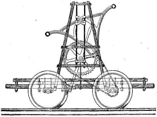
In the accompanying illustration we show a new design of hand car, being introduced by the Courtright Manufacturing Co., of Detroit. It will be seen that the apparatus for propelling the car is very different from the mechanism generally used. An upright framework secured to the platform carries a large sprocket wheel, which is connected to a smaller one upon one of the axles by means of a chain. The larger sprocket wheel is rotated by means of a triangular shaped lever attached at the lower corner to the crank of the sprocket wheel and having a handle at each of its upper corners. It is hinged upon a fulcrum which slides upon the two vertical rods shown in the illustration. It will be seen that this gives a peculiar movement to the handles by which the operators propel the car, but it has been found that the motion is an excellent one, and it is claimed that a higher speed can be obtained with the mechanism here shown than with any other now in use. There is practically no dead center, as in the case where the ordinary crank and lever is used. A number of leading roads have given the car a trial, and being well satisfied it, have given orders for more. The company claim that a car with 20 in. wheels can easily be made to attain a speed of 15 miles an hour by two men.—Railway Review.
In Fig. 1 let D be a given point, and O the center of
a given circle, whose diameter is FG. Bisect DF at
A. Also about D describe an arc with any radius DP
greater than DA, and about O another arc with a radius
OP = DP + FO, intersecting the first arc at P,
then draw PD, and also PO, cutting the circumference
of the given circle in L. Since PD = PL, and
DA = AF, it is evident that by repeating this process
we shall construct a curve PAR, which satisfies the
condition that every point in it is equally distant from
a given point and from the circumference of a given
circle. Since PO-PD = LO, and AO-AD = FO,
this curve is one branch of the hyperbola of which D
and O are the foci.
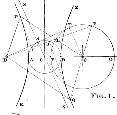
Bisect DG at B, then about D describe an arc with any radius DQ greater than DB, and about O another are with radius OQ = DQ-FO; draw from Q the intersections of these arcs, the line QD, and also QO, producing the latter to cut the circumference in E. By this process we may construct the curve QBZ, each point of which is also equally distant from the given point D, and from the concave instead of the convex arc of the given circumference. The difference between QD and QO being constant and equal to FO, and AB being also equal to FO, this curve is the other branch of the same hyperbola, whose major axis is equal to the radius of the given circle.
The tangent at P bisects the angle DPL, and is perpendicular to DL, which it bisects at a point I on the circumference of the circle whose diameter is AB, the major axis, the center being C, the middle point of DO. As P recedes from A, it is evident that the angles P D L, P L D, will increase, until DL assumes the position D T tangent to the given circle, when they will become right angles. P will therefore be infinitely remote, and the point I having then reached t, where D T touches the smaller circle, C t S will be an asymptote to the curve. This shows that the measurements from the convex arc, for the construction of A P, are made only from the portion FT of the given circumference.
In the diagram the point Q is so chosen that DL produced passes through E, so that QJ, the tangent at Q, is parallel to PI. It will thus be seen that the measurements from the concave arc, for the construction of BQ, are confined to the portion G T of the given circumference. As DLE rises, the points P and Q recede from A and B, the points L and E approach each other, finally coinciding at T; at this instant I and J fall together at t, so that S S is the common asymptote to A P and B Q.
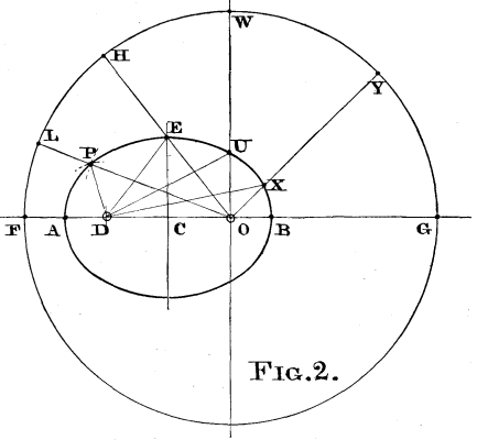 In Fig. 2 the given point D lies within the circumference
of the given circle. Bisect DF at A, and DG
at B; about D describe an arc with any radius DP
greater than DA, and about O another, with radius
OP = OF - DP, these arcs intersect in P, and producing
OP to cut the circumference in L, we have PD = PL.
Similarly ED = EH, UD = UW, etc.
And since PD + PO = LP + PO, DE + EO = HE
+ EO, and so on, the curve is obviously the ellipse of
which the foci are D and O, and the major axis is AB
= FO, the radius of the given circle.
In Fig. 2 the given point D lies within the circumference
of the given circle. Bisect DF at A, and DG
at B; about D describe an arc with any radius DP
greater than DA, and about O another, with radius
OP = OF - DP, these arcs intersect in P, and producing
OP to cut the circumference in L, we have PD = PL.
Similarly ED = EH, UD = UW, etc.
And since PD + PO = LP + PO, DE + EO = HE
+ EO, and so on, the curve is obviously the ellipse of
which the foci are D and O, and the major axis is AB
= FO, the radius of the given circle.
If, as in Fig. 3, the given point be made to coincide
with the center of the circle, the ellipse becomes a
circle with diameter A B = F O. But if the point be
placed upon the circumference, as in Fig. 4, the ellipse
will reduce to the right line A B coinciding with FO.
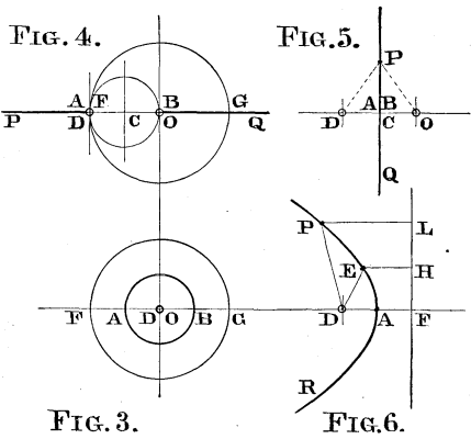
In this case we may also apply the same process as in Fig. 1; D T becomes a tangent at D to the circumference, and the asymptotes coincide with the axis of the hyperbola, of which one branch reduces to the right line A P extending from A to infinity on the left, and the other reduces to the right line B G Q, extending from B to infinity on the right.
If the circle be reduced to a point, as in Fig. 5, the resulting locus is a right line perpendicular to and bisecting D O. If on the other hand the diameter of the given circle be infinite, the circumference, as in Fig. 6, becomes a right line perpendicular to the axis at F, and the curve satisfies the familiar definition of the parabola, D E being equal to E H, D P equal to P L, and so on.
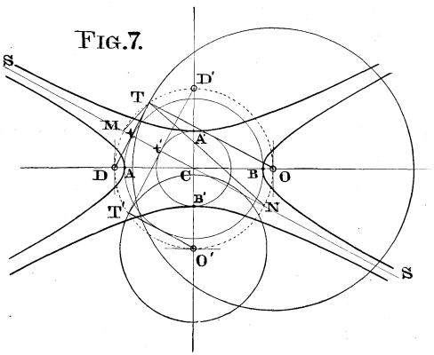 In Fig. 7, as in Fig. 1, DT is tangent at T to the
given circle whose center is O, and at t to the circle
about C whose diameter is AB, the major axis. Since
DTO is a right angle, T lies upon the circumference
of the circle whose center is C, and diameter DO; this
circle cuts the asymptote SCS at M and N. The
semi-conjugate axis is a mean proportional between D
A and AO; now drawing TM and TN, it is seen
that Tt is that mean proportional; and a circle described
about C with that radius will be tangent to TO. DT,
then, is the radius of the circle to be described about the
focus of the conjugate hyperbola for its construction
according to the enunciation first given: and we observe
that DT and TO are supplementary chords in
the circle about C through D and O. The conjugate
foci must therefore lie upon this circumference, at D'
and O'; and since D'O' is perpendicular to DO, D'T
will be perpendicular and T'O' will be parallel to
SCS.
In Fig. 7, as in Fig. 1, DT is tangent at T to the
given circle whose center is O, and at t to the circle
about C whose diameter is AB, the major axis. Since
DTO is a right angle, T lies upon the circumference
of the circle whose center is C, and diameter DO; this
circle cuts the asymptote SCS at M and N. The
semi-conjugate axis is a mean proportional between D
A and AO; now drawing TM and TN, it is seen
that Tt is that mean proportional; and a circle described
about C with that radius will be tangent to TO. DT,
then, is the radius of the circle to be described about the
focus of the conjugate hyperbola for its construction
according to the enunciation first given: and we observe
that DT and TO are supplementary chords in
the circle about C through D and O. The conjugate
foci must therefore lie upon this circumference, at D'
and O'; and since D'O' is perpendicular to DO, D'T
will be perpendicular and T'O' will be parallel to
SCS.
Now as TO increases, T'O' will diminish, until, when TO equals DO, T'O' will vanish and with it Ct'; and at this crisis, the case is the same as in Fig. 4; but the conjugate hyperbola logically reduces to two right lines, extending from C to infinity on the right and left. As indeed it should from the familiar construction, since the distances from D' and O' to any point on the horizontal axis being equal, their difference is constant and equal to zero.
It appears, then, that a conic section may be defined as the locus of a point which is equally distant from a given point and from the circumference of a given circle. Boscovich defines it as the locus of a point so moving that its distances from a given point and from a given right line shall have a constant ratio.
The latter definition involves the conceptions of a rectilinear directrix, and a varying ratio in the cases of the different curves, this ratio being unity for the parabola, less for the ellipse, and greater for the hyperbola. The former involves the conception of a circular directrix with a ratio equal to unity in all cases; and the two definitions become identical in the construction of the parabola, which is in fact the only curve of which a clear idea is given by either of them. That of Boscovich has been given a prominence far in excess of its merits, being made the foundation for the discussion of these important curves, and this in a textbook whose preface contains the following true and emphatic statement, viz.:
"The abstract nature of a ratio, and the fact that it is a compound concept, peculiarly unfit it for elementary purposes."
The definition herein set forth has not been given in any treatise on the subject, so far as we have been able to ascertain. And it is presented with the distinctly expressed hope that it never will be, except as a mere matter of abstract interest.
Of this it may, like the other, possess a little, but both have the great disadvantage that, except in relation to the parabola, the idea which they convey to the mind of the curves to which they relate, if indeed they convey any at all, is most obscure and indirect; and of practical utility neither one can claim a particle.
By request of the Committee of Revision and Publication of the Pharmacopoeia of the United States of America, Prof. F.W. Clarke, chief chemist of the United States Geological Survey, has furnished a table of atomic weights, revised upon the basis of the most recent data and his latest computations. The committee has resolved that this table be printed and furnished for publication to the professional press. The committee also requests that all calculations and analytical data which are to be given in reports or contributions intended for its use or cognizance be based upon the values in the table. It would be highly desirable that this table be adopted and uniformly followed by chemists in general, at least for practical purposes, until it is superseded by a revised edition. It would only be necessary for any author of a paper, etc., to state that his analytical figures are based upon "Prof. Clarke's table of atomic weights of December 6, 1890," or some subsequent issue.
This table represents the latest and most trustworthy results, reduced to a uniform basis of comparison, with
oxygen = 16 as starting point of the system. No decimal places representing large uncertainties are used. When values vary, with equal probability on both sides, so far as our present knowledge goes, as in the case of cadmium (111.8 and 112.2), the mean value is given in the table.
The names of elements occurring in pharmaceutical, medicinal, chemicals, are printed in italics:
| Name. | Symbol. | Atomic Weight. |
|---|---|---|
| Aluminum. | Al | 27. |
| Antimony. | Sb | 120. |
| Arsenic. | As | 75. |
| Barium. | Ba | 137. |
| Bismuth. | Bi | 208.9 |
| Boron. | B | 11. |
| Bromine. | Br | 79.95 |
| Cadmium. | Cd | 112. |
| Caesium. | Cs | 132.9 |
| Calcium. | Ca | 40. |
| Carbon. | C | 12. |
| Cerium. | Ce | 140.2 |
| Chlorine. | Cl | 35.45 |
| Chromium. | Cr | 52.1 |
| Cobalt. | Co | 59. |
| Columbium.1 | Cb | 94. |
| Copper. | Cu | 63.4 |
| Didymium.2 | Di | 142.3 |
| Erbium. | Er | 166.3 |
| Fluorine. | F | 19. |
| Gallium. | Ga | 69. |
| Germanium. | Ge | 72.3 |
| Glucinum.3 | Gl | 9. |
| Gold. | Au | 197.3 |
| Hydrogen. | H | 1.007 |
| Indium. | In | 113.7 |
| Iodine. | I | 126.85 |
| Iridium. | Ir | 193.1 |
| Iron. | Fe | 56. |
| Lanthanum. | La | 138.2 |
| Lead. | Pb | 206.95 |
| Lithium. | Li | 7.02 |
| Magnesium. | Mg | 24.3 |
| Manganese. | Mn | 55. |
| Mercury. | Hg | 200. |
| Molybdenum. | Mo | 96. |
| Nickel. | Ni | 58.7 |
| Nitrogen. | N | 14.03 |
| Osmium. | Os | 191.7 |
| Oxygen.4 | O | 16. |
| Palladium. | Pd | 106.6 |
| Phosphorus. | P | 31. |
| Platinum. | Pt | 195. |
| Potassium. | K | 39.11 |
| Rhodium. | Rh | 103.5 |
| Rubidium. | Rb | 85.5 |
| Ruthenium. | Ru | 101.6 |
| Samarium. | Sm | 150. |
| Scandium. | Sc | 44. |
| Selenium. | Se | 79. |
| Silicon. | Si | 28.4 |
| Silver. | Ag | 107.92 |
| Sodium. | Na | 23.05 |
| Strontium. | Sr | 87.6 |
| Sulphur. | S | 32.06 |
| Tantalum. | Ta | 182.6 |
| Tellurium. | Te | 125. |
| Terbium. | Tb | 159.5 |
| Thallium. | Tl | 204.18 |
| Thorium. | Th | 232.6 |
| Tin. | Sn | 119. |
| Titanium. | Ti | 48. |
| Tungsten. | W | 184. |
| Uranium. | U | 239.6 |
| Vanadium. | V | 51.4 |
| Yterbium. | Yb | 173. |
| Yttrium. | Yt | 89.1 |
| Zinc. | Zn | 65.3 |
| Zirconium. | Zr | 90.6 |
—Am. Jour. Pharm.
[1]The tanning materials of Europe are of an altogether different type from those of the United States. The population is so dense that the quantity of home materials produced is not nearly proportionate to the amount consumed, and consequently they must draw upon surrounding lands for their supply. The vegetation of these adjacent countries is of a much more tropical nature, and it naturally follows that the tanning materials are also of a different species.
Tanning materials may be divided into two great classes, viz.: Physiological and pathological.
The first class includes those tannins which are the results of perfectly natural or normal growth, and a growth necessary to the development of vegetation, for instance, bark, sumac, etc., whereas the second class contains those which are the results of abnormal growth, caused by diseases, stings of insects, etc. An example of this is the gall. Both of these classes are used to a great extent in Europe, while only the first division is in general use in the United States. We will first consider the physiological tannins.
Oak Bark.—This material was, is, and will be for some time to come the main tanning material in use here in Europe. The advantages of the oak tannage are as fully appreciated here as in the United States. The European oak gives a light colored, firm leather, with good weight results, is comparatively cheap and of an excellent quality. The varieties are numerous, each country having its own kind. Those in most general use are:
Spiegel Rinde (mirror bark).—This bark is well distributed throughout Europe, and is peeled when the tree has attained a growth of from 12 to 24 years. It is marketed in three grades.
Reitel Rinde—Is obtained from the same tree as the spiegel rinde, but after the tree has attained a growth of from 25 to 40 years.
Alte Pische (old oak).—Obtained from the aged tree. It is not as valuable as the younger bark, and consequently brings a much lower price.
Spiegel rinde may be judged by small warts which appear on the shining surface of the bark. The presence of a great number of these, as a rule, indicates a high tannin percentage.
Bosnia has fine oak trees, the bark containing 10 to 11 per cent. tannin.
Bohemia has the trauben eiche (grape oak).
France uses the kirmess oak, which grows in the south of that country and in northern Africa. Two grades are made, viz., root and trunk.
Tyrol has the evergreen oak—12 to 13 per cent. tannin.
Sardinia possesses a cork oak, which yields 13 to 14 per cent.
White oak is found throughout Europe, yielding 10 per cent. The price of oak bark varies a great deal. The assortment is much more strict than in the United States. In Austria it brings 4 to 5 fl., equal to $1.60 to $2 per kilo. (224 lb.); in Germany, 11 to 16 marks per 100 kilos.1
The above mentioned varieties are all used for both upper and sole leather. In Germany a great deal of upper leather is pure oak tannage, but one seldom finds a pure oak tanned sole leather; it is almost always in combination with other tannics.
Pine Bark—Is well distributed and is a very important tanning material. It bears the same relation to oak bark here as does hemlock in America, but its effects are quite different from hemlock. The best Austrian sorts are those of Styria and Bohemia, but that of Karuthen is also of good quality. The German pine comes from Thuringia to a great extent. The countries that consume the greatest amount of pine bark are Austria, Germany, Russia and Italy. The tannin contained varies from 5 to 16 per cent. Its use is almost wholly confined to the handlers, as its weight returns are not so satisfactory as oak or valonia. In case it should be used for layers it is always in combination with some better weight-giving tannic. For upper leather its use is limited.
The bark is always peeled from the felled tree, and often the woodman accepts the bark in part payment for his labor; he then sells the bark to the tanner or agents who go about the country collecting bark. It is generally very nicely cleaned. I would here like to correct a mistake which tanners often make in their estimations of the value of barks. A tanner usually buys the bark of southern-grown trees in preference to that of trees grown in northern countries, as it is a common idea that southern vegetation contains more tannin than that of the north. This is a fallacy, as has not only been proved by careful analyses, but may also be found to be an incorrect conclusion after a moments' thought. Those trees which flourish in southern countries grow very rapidly, and as tannin is necessary to the development of leaf structure, etc., it is absorbed to a greater extent than is the case with the slower-growing tree of the north. The tannin contained in the sap does not increase in the same ratio as does the rapid growth, and it follows that the remainder in the bark is less than in the tree of slower growth.
Birch Bark—Is at home in Russia, Norway, and Sweden. It is used for both upper and sole leather, but seldom alone. The bark is usually peeled from the full grown tree, and contains 4 to 9 per cent. tannin.
Willow Bark—May also be found in the above mentioned countries and also in Germany. This material is used for both upper and sole leather, and contains 6 to 9 per cent. tannin. It is a very delicate material to use, as its tannin decomposes rapidly.
Erlen Rinde—Is also a native of Germany, but is not used to any great extent. The same may be said of the larch, although this variety is also to be met with in Russia.
Mimosa Bark—Is obtained from the acacia of Australia. It is a favorite in England. The varieties are as follows: Gold wattle, silver wattle (blackwood, lightwood), black wattle, green wattle. The gold wattle is a native of Victoria. Its cultivation was tried as an experiment in Algeria and met with some success. The trees are always grown from seeds. These seeds are laid in warm water for a few hours before sowing. The acacia may be peeled at eight years' growth and carries seeds. The Tasmania bark is very good; that from Adelaide likewise good.
Sydney does not produce so good an article, but Queensland better. The bark is marketed in the stick, ground or chopped.
Madagascar and the Reunion Islands have also a mimosa bark.
The mimosa barks give a reddish colored leather, pump well and contain a high tannin percentage, 10 to 35 per cent.
Now we will consider the fruit tanning materials.
Valonia may truly be called one of the most generally used tanning agents at present employed in Europe. All countries consume it more or less. Valonia was first used in England about the beginning of this century. A few years later Germany began using it, and still later Austria introduced it. It is the fruit of the oak tree and is obtainable in Asia Minor and the adjacent islands. In form it resembles the American acorn, but in size it nearly trebles it. The fruit may be divided into two parts, namely, the cup and acorn, and the cup again divided into trillor and inner cup. The acorn only contains 10 per cent. tannin, whereas the cup contains from 25 to 40 per cent.
The percentage depends altogether upon the time of harvesting and the place of growth. The best valonia is derived from Smyrna, and is naturally the highest priced article. Valonia is worth from 22 to 28 florins ($9 to $11) per 100 kilos. (224 pounds) at present. The other provinces and islands from which it is obtainable are Demergick, Govalia, Idem, Ivalzick, Troy (this is the best); Metelino Island, the vicinity of Smyrna. The material sold in three grades—prime, mazzano; seconds, una aqua; thirds, skart.
The product of Smyrna generally averages:
| Tons. | Price. | |
| Prime. | 2,000 to 3,000 | 28 florins. |
| Seconds. | 5,000 to 10,000 | 25 florins. |
| Thirds. | 20,000 to 30,000 | 22 florins. |
The Metilino valonia is a product of a neighboring island, and is a very good article. It may be easily distinguished by its thin cup. It is harvested in September.
The Candia valonia is nearly as long as it is wide, in contrast to the Smyrna, which is much wider than long. The recent harvest showed a return of 800 to 1,000 tons, but no assortment is made. A grade called the Erstlige is sold, this being the first which has fallen to the ground before maturing.
A peculiarity of the valonia is that it often strikes out a sort of sugar sweat, which gives the cup a less attractive appearance, but denotes the presence of large quantities of tannin.
Valonia is used almost wholly for sole leather, either alone or in combination with pine or oak bark or knoppern and myrabolams. The union of valonia and knoppern is that in most general use. Valonia gives the leather a yellowish appearance, as it deposits a great deal of yellow bloom. The leather is very firm and of good wearing qualities. The weight results are also excellent, as will be seen below. To sole leather there are usually given from one to three layers of valonia. The demand for valonia is increasing more and more every year, and the present outlook does not indicate any relaxation of its popularity. Its use for upper leather is very limited.
Myrabolams are mainly used in England and Austria, and give a nice light-colored leather, both upper and sole, although rarely used alone. Their main use is for dyeing purposes. They are indigenous to the East Indies.
Sumac is so well known that treating of it is superfluous. Its use is very extensive, and it is a general favorite for light, fine leather, which is mostly used for colors.
Gambier—Is in general use in England and to some extent in Germany.
Catechu.—Obtained from India, resembles gambier greatly. Its use is almost wholly confined to England. It is also consumed by the silk manufacturers in preference to gambier, for weighting purposes.
We now leave the physiological class and take up those tanning materials included in the pathological class, or those of abnormal growth.
Galls.—These are not consumed to any great extent at the present period, but formerly they were used quite extensively. The galls are found upon the leaves of the oak or sumac, etc. The direct cause of their growth is that a certain wasp (cynips galles) stings into the leaf and after depositing its egg, flies away. The egg develops into a larva and then into a full-fledged wasp, boring its way out of the gall which has served as a protection and nourisher. This accounts for the hole noticed in almost every gall. The different varieties include Aleppo. It is found upon the same trees as the valonia and contains 60 to 75 per cent. tannin; Istrian galls, 32 per cent. tannin; Persian, 28 to 29 per cent. tannin. Chinese galls, giving 80 to 82 per cent. tannin, are the results of the sting of a louse, and make a very light-colored leather. The dyers also use this material for coloring.
Knoppern—Belongs to the family of galls, and is a most important factor of commerce in Austria. The knopper is generally found on the acorn or leaf of the oak tree. The greatest quantity is derived from the steel oak of Hungary. The tannin contained varies from 27 to 33 per cent. Knoppern are not being used so much now as formerly, and consequently the amount harvested lessens from year to year. Its main use was and is in combination with valonia as layers for sole leather. Valonia gives better weight results than knoppern, and is replacing knoppern more and more every year. The combination of knoppern, valonia and myrabolams is also quite popular, and gives good results. Knoppern are seldom used alone, being generally combined with some other tannin. Austria is almost the only consumer at present, but Germany used it extensively formerly.
Bark and Wood Extracts—Are becoming general favorites throughout Europe, partly because of their weight-giving qualities and partly as the transportation costs so little; they can be used to strengthen weak bark liquors.
Oak Extracts—Are well liked, both wood and bark, and are used extensively. Slavonia furnishes a great deal of it.
Chestnut Oak Wood Extract—Is manufactured in quantities, and easily finds purchasers.
Pine Bark Extract—Is also consumed in goodly amounts.
Quebracho Wood Extract.—The wood is shipped from Brazil to Hamburg and other ports, and the tannin extracted there. Hamburg furnishes quantities of it.
Hemlock Extract—Is used in Russia, and seems to have taken a hold on the shoe buyers' fancies, as they now make imitations of it in color. The hemlock that is consumed is imported from America.
As most leather is sold by weight in Europe, the leather manufacturers aim to obtain as good weight results as possible, and often, I am sorry to say, do so at the sacrifice of quality. This is common to both upper and sole leather. Sole leather is nine times out of ten given false weight by forcing entirely foreign substances into the leather, such as glucose, barium chloride, magnesium chloride, resins, etc. Glucose and resin are also used for weighting upper leather. Leather is also weighted with extracts by overtanning. Leather buyers have become very wary of late and do not purchase large quantities before an analysis is made of a fair sample.
One more word before I close. The governments and private individuals in Europe cultivate and raise trees for both lumber and bark purposes. The forests are excellently cared for by efficient foresters, and the result is that the tanners obtain much cleaner and better bark, and of a very even quality. Would it not be a good idea if some individual, who would certainly earn the everlasting gratefulness of the tanners, would look into this matter, and see that not only the lumber side of our forest cultivation is not neglected, but that the bark also is preserved and cared for? Of course, we can obtain all the bark necessary at present and for some time to come, but the time will come when we shall certainly regret not having taken these steps, if the lumbermen and bark peelers go on devastating magnificent forests. Below will be found a table of weight results. Sole leather tanned with these materials gives for every 100 lb. green hide the following quantities of finished leather:
| lb. | |
| Oak bark | 48 to 54 |
| Oak extract | 55 to 56 |
| Pine bark | 44 to 46 |
| Pine extract | 48 to 50 |
| Willow | 45 to 46 |
| Birch bark and oak extract | 49 to 51 |
| Quebracho wood and extract | 48 to 49 |
| Valonia | 52 to 56 |
| Knoppern | 51 to 53 |
| Myrabolams | 50 |
| Knoppern, myrabolams and valonia | 52 to 53 |
| Hemloc | 55 |
Specification of tanning materials used in different countries:
   France.
      Oak bark (kirmess).
      Sumac.
      Chestnut wood extract.
      Quebracho "     "
      Some gambier.

   Italy.
      Oak bark.
      Pine "
      Sumac.
      Valonia.

   England.
      Oak bark.
      Divi divi.
      Myrabolams.
      Valonia.
      Mimosa.
      Extracts { Oak bark and wood hemlock.
      Gambier.
      Cutch.

   Germany and Austria.
      Oak bark.
      Pine "
      Willow bark.
      Valonia.
      Knoppern.
      Myrabolams.
               { Oak bark and wood.
      Extracts { Pine bark and wood.

   Russia.
      Birch bark.
      Willow "
      Oak    "
      Pine   "
      Hemlock extract.


   Norway and Sweden.
      Birch bark.
      Willow "
      Oak    "
Chemists who do not happen to have in their laboratories oil or air baths for heating closed tubes can make an air bath at short notice from materials furnished by all dealers in steam fittings.
Order:
(1) One four-inch wrought iron pipe, eighteen inches out to out, with usual thread on each end. At about nine inches from either end this pipe is drilled and tapped for a one-inch nipple, in such a manner that a pipe introduced would pass, not on a line with the radius, but about half way between the axis of the four-inch pipe and its walls; in other words, it would be on a line with a chord of the circle.
(2) One one-inch wrought iron nipple, two inches long, one-inch thread on one end.
(3) Two four-inch malleable iron caps, drilled and tapped for a one-inch pipe.
(4) One one-inch wrought iron pipe, twenty-four inches out to out, with a three-inch straight thread on each end.
(5) Two one-inch iron caps. A hole, one-eighth of an inch in diameter, is drilled in the end of one of these caps.
The above order can be given literatim, and will be understood by the dealer, who will furnish, at a trifling cost, the materials, cut and tapped as ordered.
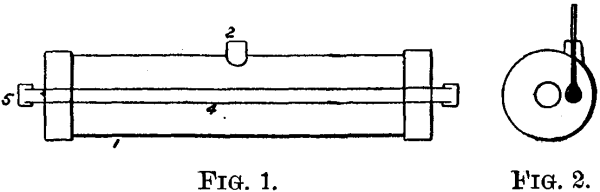 Fig. 1 shows how the whole is put together. The
numbers on the figure correspond also to the numbers
of the paragraphs of the order as given above.
Fig. 1 shows how the whole is put together. The
numbers on the figure correspond also to the numbers
of the paragraphs of the order as given above.
Fig. 2 is an end section. A cork is inserted in 2 and through it a thermometer, the bulb of which is on a level with the interior pipe. The whole is supported on a few bricks at either end, and is kept steady and in place by a couple of weights or half bricks. It is heated by one or two Bunsen burners, according to the temperature desired.—Jour. Fr. Institute.
[1]An improved method of testing Portland cement has been adopted by M. Deval, Chief Superintendent of Bridges and Roads, who has charge, under M. Saele, of the Public Works Laboratory of the City of Paris. The principal difference in M. Deval's method consists in the use of hot water for the period of hardening. The briquettes are made in the usual way, and of the ordinary size; and the cement to be tested is gauged with three times its weight of normal sand, and the smallest quantity of water possible. After preparation, the briquettes are allowed to harden in air for a period ranging from 24 hours for Portland cement to 30 days for certain slow-setting hydraulic limes. After this period, the samples are immersed in water kept at a temperature of 80° C., in which they remain for from two to seven days. The briquettes are then broken in the ordinary way. After careful comparisons of many varieties of cement hardened hot and cold, M. Deval finds that cold tests are fallacious, inasmuch as they may fail to detect bad material. Portland cement of good quality will not only stand water at 80° C., but will attain in seven days about the same strength as is reached in the cold after 28 days. The hot test therefore saves time. The hot test is an unfailing proof for free lime; cements containing this constituent betraying weakness, and cracking, swelling, and disintegrating in a very significant manner. This last result is regarded as a valuable quality of the new method of testing cement, the general effect of which appears to be to enhance the test value of really good cements, while depreciating those of an inferior character.
This is a Special Edition of the SCIENTIFIC AMERICAN, issued monthly—on the first day of the month. Each number contains about forty large quarto pages, equal to about two hundred ordinary book pages, forming, practically, a large and splendidMagazine of Architecture, richly adorned with elegant plates in colors and with fine engravings, illustrating the most interesting examples of modern Architectural Construction and allied subjects.
A special feature is the presentation in each number of a variety of the latest and best plans for private residences, city and country, including those of very moderate cost as well as the more expensive. Drawings in perspective and in color are given, together with full Plans, Specifications, Costs, Bills of Estimate, and Sheets of Details.
No other building paper contains so many plans, details, and specifications regularly presented as the SCIENTIFIC AMERICAN. Hundreds of dwellings have already been erected on the various plans we have issued during the past year, and many others are in process of construction.
Architects, Builders, and Owners will find this work valuable in furnishing fresh and useful suggestions. All who contemplate building or improving homes, or erecting structures of any kind, have before them in this work an almost endless series of the latest and best examples from which to make selections, thus saving time and money.
Many other subjects, including Sewerage, Piping, Lighting, Warming, Ventilating, Decorating, Laying out of Grounds, etc., are illustrated. An extensive Compendium of Manufacturers' Announcements is also given, in which the most reliable and approved Building Materials, Goods, Machines, Tools, and Appliances are described and illustrated, with addresses of the makers, etc.
The fullness, richness, cheapness, and convenience of this work have won for it the Largest Circulation of any Architectural publication in the world.
A Catalogue of valuable books on Architecture, Building, Carpentry, Masonry, Heating, Warming, Lighting, Ventilation, and all branches of industry pertaining to the art of Building, is supplied free of charge, sent to any address.
MUNN & CO., Publishers,
361 Broadway, New York.
In connection with the publication of the BUILDING EDITION of the SCIENTIFIC AMERICAN, Messrs. Munn & Co. furnish plans and specifications for buildings of every kind, including Churches, Schools, Stores, Dwellings, Carriage Houses, Barns, etc.
In this work they are assisted by able and experienced architects. Full plans, details, and specifications for the various buildings illustrated in this paper can be supplied.
Those who contemplate building, or who wish to alter, improve, extend, or add to existing buildings, whether wings, porches, bay windows, or attic rooms, are invited to communicate with the undersigned. Our work extends to all parts of the country. Estimates, plans, and drawings promptly prepared. Terms moderate. Address
MUNN & CO., 361 BROADWAY, NEW YORK.
Sent by mail, postage prepaid, to subscribers in any part of the United States or Canada. Six dollars a year, sent, prepaid, to any foreign country.
All the back numbers of THE SUPPLEMENT, from the commencement, January 1, 1876, can be had. Price, 10 cents each.
All the back volumes of THE SUPPLEMENT can likewise be supplied. Two volumes are issued yearly. Price of each volume, $2.50 stitched in paper, or $3.50 bound in stiff covers.
COMBINED RATES.—One copy of SCIENTIFIC AMERICAN and one copy of SCIENTIFIC AMERICAN SUPPLEMENT, one year, postpaid, $7.00.
A liberal discount to booksellers, news agents, and canvassers.
MUNN & CO., Publishers,
361 Broadway, New York, N.Y.
Contained in SCIENTIFIC AMERICAN SUPPLEMENT during the past ten years, sent free of charge to any address. MUNN & CO., 361 Broadway, New York.
Manufacturers, Agriculturists, Chemists, Engineers, Mechanics, Builders, men of leisure, and professional men, of all classes, need good books in the line of their respective callings. Our post office department permits the transmission of books through the mails at very small cost. A comprehensive catalogue of useful books by different authors, on more than fifty different subjects, has recently been published, for free circulation, at the office of this paper. Subjects classified with names of author. Persons desiring a copy have only to ask for it, and it will be mailed to them. Address,
MESSRS. MUNN & CO., in connection with the publication of the SCIENTIFIC AMERICAN, continue to examine improvements, and to act as Solicitors of Patents for Inventors.
In this line of business they have had forty-five years' experience, and now have unequaled facilities for the preparation of Patent Drawings, Specifications, and the prosecution of Applications for Patents in the United States, Canada, and Foreign Countries. Messrs. Munn & Co. also attend to the preparation of Caveats, Copyrights for Books, Labels, Reissues, Assignments, and Reports on Infringements of Patents. All business intrusted to them is done with special care and promptness, on very reasonable terms.
A pamphlet sent free of charge, on application, containing full information about Patents and how to procure them; directions concerning Labels, Copyrights, Designs, Patents, Appeals, Reissues, Infringements, Assignments, Rejected Cases. Hints on the Sale of Patents, etc.
We also send, free of charge, a Synopsis of Foreign Patent Laws, showing the cost and method of securing patents in all the principal countries of the world.
BRANCH OFFICES.—No. 622 and 624 F Street, Pacific Building,
near 7th Street, Washington, D.C.