The Project Gutenberg EBook of Scientific American Supplement, No. 514,
November 7, 1885, by Various

This eBook is for the use of anyone anywhere at no cost and with
almost no restrictions whatsoever.  You may copy it, give it away or
re-use it under the terms of the Project Gutenberg License included
with this eBook or online at www.gutenberg.org


Title: Scientific American Supplement, No. 514, November 7, 1885

Author: Various

Release Date: April 3, 2004 [EBook #11761]

Language: English

Character set encoding: ISO-8859-1

*** START OF THIS PROJECT GUTENBERG EBOOK SCIENTIFIC AMERICAN 514 ***


Produced by Jon Niehof, Don Kretz, Juliet Sutherland, Charles Franks
and the DP Team
The Roman tessellated pavement in Jewry Wall Street, Leicester, discovered in the year 1832, is well known to archaeologists; it has also been known as difficult of access, and hardly to be seen in a dark cellar, and, in fact, it has not been seen or visited, except by very few persons. Some time ago the Town Council resolved to purchase the house and premises, with the object of preserving the pavement in situ, and of giving additional light and better access to it, and, this purchase having been completed in the beginning of the present year, the work of improvement began. It was now seen that the pavement was continuous under the premises of the adjoining house, and under the public street, and arrangements were at once made to uncover and annex these adjoining parts, so as to permit the whole to be seen at one view. The pavement thus uncovered forms a floor which, if complete, would measure 23 feet square; it lacks a part on the west side, and also the entire south border is missing. It is a marvel of constructive skill, of variety and beauty in form and color, and not the least part of the marvel arises from the almost beggarly elements out of which the designer has produced his truly harmonious effects. No squared, artificially colored, or glazed tesseræ, such as we see in a modern floor, are used, but little pieces, irregularly but purposely formed of brick and stone. There are three shades of brick—a bright red, a dull or Indian red, and a shade between the two; slate from a neighboring quarry gives a dark bluish gray; an oolite supplies the warmer buff; and a fine white composition resembling limestone is used for the center points and borders. In addition, the outside border is formed with tesseræ of rather larger size of a sage green limestone. Speaking generally, the design is formed by nine octagon figures, three by three, surrounded and divided by a guilloche cable band; the interspaces of the octagons are filled by four smaller square patterns, and the outer octagon spaces by 12 triangles. Outside these is a border formed by a cable band, by a second band of alternate heart-shaped, pear-shaped, and bell-shaped flowers, and by alternate white and gray bands; and outside all is the limestone border already described. This border is constructed with tesseræ about five-eighths of an inch square. The remaining tesseræ vary from one half to one-quarter inch of irregular rhomboidal form. The construction of the pavement is remarkable. There is a foundation of strong concrete below; over it is a bed of pounded brick and lime three to four inches thick, and upon this a layer of fine white cement, in which the tesseræ are laid with their roughest side downward. Liquid cement appears to have been poured over the floor, filling up the interstices, after which the surface would be rubbed down and polished.
As to the probable date and occupation of the floor, it may be observed that the site of this pavement was near the center of the western Roman town. It is near the Jewry Wall, that is, near the military station and fortress. It was obviously the principal house in the place, and as clearly, therefore, the residence of the Præfectus, the local representative of the imperial power of Rome. The Roman occupation of the district began with the proprætorship of Ostorius Scapula, A.D. 50. He was succeeded in 59 by Suetonius Paulinus, who passed through Leicester from the Isle of Anglesea when the insurrection under Boadicea broke out. In the service of Suetonius was Julius Agricola, who was elected consul and governor of Britain about the year 70. He is commonly described as a wise and good governor, who introduced the arts of civilized life, taught the natives to build, and encouraged education. He left Britain about the year 85, and from that time to the decline of the Roman power is but about 300 years. We shall not be far from the truth, therefore, if we assign this work to the time or even to the personal influence of Agricola, 1,800 years ago.—London Times.
Some time ago we published the fact that the Empress of Germany had offered a prize of $1,000 and the decoration of the Order of the Red Cross to the successful inventor of the best portable field hospital. Wm. M. Ducker, of No. 42 Fulton St., Brooklyn, sent in a design for competition. A few days ago Mr. Ducker received notice that his invention had won the prize. Another instance of the recognition of American genius abroad.
The question whether Barbara Uttmann, of Annaberg, Saxony, was the inventor of the art of making hand cushion lace, or only introduced it into Annaberg, in the Saxon mountains, has not yet been solved, notwithstanding the fact that the most rigid examinations have been made. It is the general belief, however, that she only introduced the art, having learned it from a foreigner in the year 1561. The person from whom she acquired this knowledge is said to have been a Protestant fugitive from Brabant, who was driven from her native land by the constables of the Inquisition, and who found a home in the Uttmann family. However, the probability is that what the fugitive showed Barbara Uttmann was the stitched, or embroidered, laces—points, so called—which are still manufactured in the Netherlands at the present time. It is very probable that the specimens shown induced Barbara Uttmann to invent the art of making lace by means of a hand cushion.
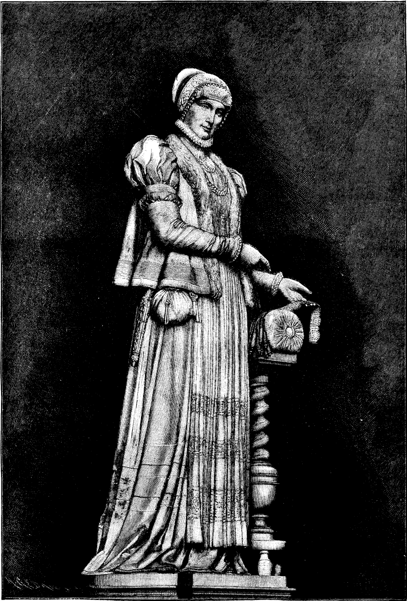
BARBARA UTTMANN, INVENTOR OF HAND CUSHION LACE.
Very little is known of the family of Barbara Uttmann, which was originally from Nurnberg; but members of the same migrated to the Saxon mountains. Barbara's husband, Christof Uttmann, was the owner of extensive mines at Annaberg, and was very wealthy. She died at Annaberg, Jan. 14, 1584.
The art of making hand cushion lace was soon acquired by most of the residents in the Saxon mountains, which is a poor country, as the occupation of most of the inhabitants was mining, and it frequently happened that the wages were so low, and the means of sustaining life so expensive, that some other resource had to be found to make life more bearable. Barbara Uttmann's invention was thus a blessing to the country, and her name is held in high esteem. A monumental fountain is to be erected at Annaberg, and is to be surmounted by a statue of the country's benefactress, Barbara Uttmann. The statue, modeled by Robert Henze, is to be cast in bronze. It represents Barbara Uttmann in the costume worn at the time of the Reformation. She points to a piece of lace, which she has just completed, lying on the cushion, the shuttles being visible.
Some point, Valenciennes, and Guipure laces are made on a cushion by hand, with bobbins on which the thread is wound, the pins for giving the desired pattern to the lace being stuck into the cushion. A yard of hand cushion lace has been sold in England for as much as $25,000. The annexed cut, representing the Barbara Uttmann statue, was taken from the Illustrirte Zeitung.
A Boston paper tells of a man who built two houses side by side, one for himself and one to sell. In the house sold he had placed a furnace against the party wall of the cellar, and from its hot air chamber he had constructed flues to heat his own domicile. The owner of the other house found it very hard to keep his own house warm, and was astounded at the amount of coal it took to render his family comfortable, while the "other fellow" kept himself warm at his neighbor's expense nearly a whole winter before the trick was discovered.
Portland cement concrete if made with a non-porous aggregate is impervious to moisture, and yet at the same time, if not hydraulically compressed, will take up a sufficient quantity of moisture from the air to prevent condensation upon the surface of the walls. It not only resists the disintegrating influences of the atmosphere, but becomes even harder with the lapse of time. It may also be made in several different colors, and can be finished off to nearly a polished surface or can be left quite rough. Walls built of this material may be made so hard that a nail cannot be driven into them, or they can be made sufficiently soft to become a fixing for joinery, and, if a non-porous aggregate be used, no damp course is required. Further than this, if land be bought upon which there is sufficient gravel, or even clay that can be burnt, the greatest portion of the building material may be obtained in excavating for the cellar; and in seaside localities, if the (salt) shingle from the beach be used, sound and dry walls will be obtained. The use of concrete as a material for building will be found to meet all the defects set forth by practical people, as it may be made fire-proof, vermin-proof, and nail-proof, and in dwellings for the poor will therefore resist the destructive efforts of the "young barbarian." Nothing, therefore, can be better as a building material. The system ordinarily employed to erect structures in concrete consists of first forming casings of wood, between which the liquid concrete is deposited, and allowed to become hard, or "to set." The casings are then removed, the cavities and other imperfections are filled in, and the wall receives a thin facing of a finer concrete. If mouldings or other ornament be required, they are applied to this face by the ordinary plasterer's methods. This system finds favor in engineering construction, and also in very simple forms of architectural work, but with very complicated work the waste in casings is very great. Besides this, however, the face is found sometimes to burst off, especially if it has been applied some time after the concrete forming the body of the wall has set, and the method of applying ornament is not economical.
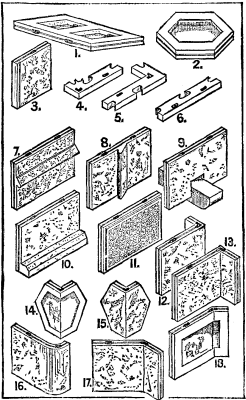
1.-18.
A system of building in concrete has recently been invented by Messrs. F. & J.P. West, of London, illustrations of which we now present. To this system Messrs. West have given the name of "Concrete Exstruction," from the Latin "exstructio," which they consider to be a more appropriate word than "constructio," as applied to concrete building in general. In Messrs. West's system of building in concrete, instead of employing wood casings, between which to deposit the concrete or beton, and removing them when the beton has become hard, casings of concrete itself are employed. These casings are not removed when the beton has set, but they become a part of the wall and form a face to the work. In order to form the casings, the concrete is moulded in the form of slabs. Figs. 1 to 18 of our engravings show various forms of the slab, which may be manufactured with a surface of any dimensions and of rectangular (Fig. 1), triangular, hexagonal (Figs. 2, 14, and 15), and indeed of any other form that will make a complete surface, while for thickness it may be suited to the work to which it is to be applied, that used for heavy engineering work differing from that employed in house construction. It is found that the most convenient height for the rectangular slab (Fig. 1) is 12 inches and the breadth 18 inches, as the parts of a structure built with slabs of these dimensions more often correspond with architectural measurements. The hexagonal slab (Fig. 2) is made to measure 12 inches between its parallel sides. Where combinations of these slabs will not coincide with given dimensions, portions of slabs are moulded to supply the deficiency. The moulds in which the slabs are made are simple frames with linings having a thin face of India-rubber or other suitable material, by the use of which slabs with their edges as shown, and also of the greatest accuracy, can be manufactured. That portion of the back of the slab which is undercut is formed by means of soft India-rubber cores. The moulds for making portions of the slabs have a contrivance by which their length may be adjusted to suit given dimensions.
During the process of casting the slabs, and while they are in a plastic state, mouldings (if required) or other ornaments, having a suitable key, are inserted in the plastic surface, which is finished off to them (Figs. 7, 8, and 10). The slabs may also be cast with ornaments, etc., complete at one operation (Fig. 11), but it is more economical to have separate moulds for the mouldings and other ornaments, and separate moulds for the slabs, and to apply the mouldings, etc., during the process of casting the slab. Corbels (Fig. 9), sets off (which would be somewhat similar to the plinth course slab No. 10), and other constructive features may also be applied in a similar way, or may be provided for during the casting of the slab. A thin facing of marble or other ornamental solid or even plastic material may be applied to the face of the slabs during the process of casting, thus enabling the work to be finished as it is carried up, or a key may be formed on the face of the slab to enable the structure to be plastered afterward.
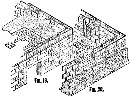
FIG. 19. FIG 20.
In Fig. 20, the structure from the bottom of the trenches is shown with the sides of the trenches removed. It will be seen that the footings are constructed in the most economical manner by not being stepped. As no damp-course is required in concrete work, when the aggregate is of a non-porous material, one is not shown. Upon the top of the footings is generally laid a horizontal slab, called the wall-base slab, the special feature of which is that it enables the thickness of the wall to be gauged accurately, and also provides a fixing for the first course of slabs. Figs. 4 and 5 show such slabs for internal and external angles, and Fig. 6 shows one for straight work. The use of a wall-base slab is not essential, although it is the more accurate method of building, for in cases where it is desirable to economize labor, or from other causes, the slabs forming the first course may be made with a thicker base, and may be fixed by a deposition of concrete, which is allowed to set behind them. The second course of slabs is laid upon the first course with breaking joints of half-slab bond, each course being keyed to the other by means of a quick-setting cementing material poured into the key-holes provided in the edges of the slab for that purpose, a bituminous cement being preferred. The key-holes are made in several ways, those shown in the illustrations being of a dovetail shape; circular, square, or indeed holes of any other shape formed in the edges of the slab and in an oblique direction are also employed. Special slabs for cants, or squint-quoins (Figs. 17 and 18) and angles (Figs. 12, 13, 14, 15, and 16) are manufactured, the angle occurring (if we omit the hexagonals and take the 18 inch slab) at three-quarters the length of each slab. This gives a half-slab bond to each course, as on one face of the quoin in one course will appear a quarter slab and in the course above a three-quarter slab superimposed upon it, or vice versa. Thus are the walls in Figs. 19 and 20 built up. For openings, the jambs and lintels (and in window-openings the sill) are made solid with a provision for a key-hole to the mass of concrete filling behind them. That portion of the jambs against which the slabs butt has a groove coinciding with a similar one in the edge of the slab, for the purpose of forming a joggle joint by squeezing the bedding material into them or by joggling them in with a cement grout. All the slabs are joggled together in a similar way.
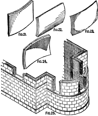
FIG. 21.-FIG 25.
The plastic concrete filling or beton which the shells are made to contain may be deposited between the slabs when any number of courses (according to convenience) have been built up, and when set practically forms with the solid work introduced a monolith, to which the face slabs are securely keyed. With over-clayed Portland cements, which are known to contract in setting, and with those over-limed cements which expand (both of which are not true Portland cements), the filling in is done in equal sections, with a vertical space equal to each section left between them until the first sections have become thoroughly hard, and these are then filled in at a second operation. In order to provide for flues, air-passages, and ways for electric installations, and for gas and water, pipes (made of an insulating material if required) or cores of the required shape are inserted in the plastic beton, and where necessary suitable openings are provided on the face of the work. Provision is also made for fixing joinery by inserting, where required, slabs made or partly made of a material into which nails may be driven, such as concrete made with an aggregate of burnt clay, coke, and such like. Hollow lintels are also made of the slabs keyed together at their vertical joints, and when in position these are filled in with beton. This system, however, is only recommended for fire-place openings instead of arches.
In Fig. 25, circular construction is exhibited as applied to the apsidal end of a church, slabs similar to those shown in Fig. 21 being employed for that purpose, while Figs. 22, 23, and 24 show forms of slabs suitable for constructing cylinders with horizontal axes and domes. In Fig. 19, which is the upper part of Fig. 20, is shown a system of constructing floors of these slabs. It is only necessary to explain that the slabs are first keyed to the lower flange of the iron joist by means of a cement (bituminous preferred), and the combination is then fixed in position, the edges of the slabs adhering to, or rather supported by, the iron joist being rebated so as to receive and support intervening slabs, the heading joints of which are laid to break with those of the slabs supported by the joists. For double floors the iron joists are made with a double flange on their lower edge, and are fitted to iron girders, which cross in the opposite direction. This provision secures the covering of the cross girders on their undersides by the ceiling slabs. The concrete having been deposited upon the slabs, its upper surface may be finished off in any of the usual ways, while the ceiling may be treated in any of the ways described for the walls. This system does not exclude the ordinary methods of constructing floors and roofs, although it supplies a fireproof system. Where required, bricks, stone, and, in fact, any other building material, may be used in conjunction with the slabs.
The system of building construction is intended, as in the case with all concrete, to supersede brickwork and masonry in the various uses to which they have been applied, and, at the same time, to offer a more perfect system of building in concrete. Hitherto slab concrete work has never been erected in a perfectly finished state (i.e., with mouldings, etc., complete), but has either been left in a rough state or without ornament, or else has been constructed so as never to be capable of receiving good ornamental treatment. Hitherto the great difficulty in constructing concrete walls of concrete and other slabs has been to prevent the slabs from being forced outward or from toppling over by the pressure of the plastic filling-in material from the time of its deposition between the slabs until it has become hard enough to form, with the slabs, a solid wall. Besides the system of forming the slabs of L (vertical or horizontal) section, or with a kind of internal buttress and shoring them up from the outside, or of supporting the slabs upon framing fixed against the faces of the wall, several devices have been used to obviate this difficulty.
In the first place, temporary ties, or gauges, connecting the slabs forming the two faces of the wall, have been used, and as soon as the plastic filling-in material has set or become hard (but not before), these have been removed. Secondly, permanent ties or cramps have been used, and, as their name implies, have been allowed to remain in the wall and to be entirely buried in the plastic filling-in material. These permanent transverse ties or cramps have been of two kinds: those which were affixed as soon as the slabs were placed in position, and those which were made to form part of the manufactured slab, as, for instance, slabs of Z or H horizontal section. Thirdly, a small layer of the plastic filling-in material itself has been made to act as a transverse tie by depositing it, when plastic, between the slabs forming the two parallel faces of each course, allowing it (before filling in the remaining part) to set and to thus connect together the slabs forming each face of the wall, a suitable hold on the slabs, in some cases, being given to the tie by a portion of the slab being undercut in some way, as by being dovetailed, etc. As the slabs in this latter system generally have wide bases, they may also be bedded or jointed in cement, and, provided temporary ties be placed across their upper edges to connect the slabs forming each face of the wall together, the space between the faces of the wall may then be filled in with the plastic concrete.
All these devices, however, are not of permanent utility; they are only temporarily required (i.e., up to the time that the beton has become hard and formed a permanent traverse tie between the two faces of the wall), for it is manifest that the ultimate object of all slab concrete construction is: (a) To retain and to mould the plastic concrete used in forming the wall; (b) to key or fix the slabs to the mass which they themselves have moulded; and (c) to form a facing to the wall. When these objects shall have been accomplished, there is no further need of any tie whatever beyond that which naturally obtains in a concrete wall. In West's system, however, where the slabs are keyed course to course, any kind of transverse tie to be used during the process of construction, except that used in the starting course, is entirely dispensed with, and the courses of slabs above depend solely upon the courses of slabs below them for their stability and rigidity up to the time that the plastic filling-in has been deposited and become hard between both faces of the wall.
CONCRETE CONSTRUCTION
There is, however, a more decided difference between West's system and those previously in use, for it is marked by the fact that the slabs composing the shell of the whole structure in many cases may be built up before the filling-in is deposited between the slabs, and in none of the other cases can this be done. In fact, only in the first two cases before mentioned can more than one course of slabs be laid before filling-in of some kind must be done. Compared with the ordinary method of building in concrete, this system avoids: 1. The charge for use and waste of wood casings; 2. finishing the face of the work (both inside and outside) after the structure is raised, and, therefore, the bursting-off of the finished face; and 3. the difficulties encountered in working mouldings and other ornaments on the face of the work by the ordinary plasterer's methods. It also provides a face of any of the usual colors that may be obtained in concrete, besides a facing of any other material, such as marble, etc., and produces better and more durable work, at the same time showing a saving in cost, especially in the better classes of work; all of which is effected with less plant than ordinarily required. For engineering work, such as sea walls, the hexagonal slabs, made of greater thickness than those employed for ordinary walling, will answer admirably, especially if the grooves be made proportionately larger. By the use of these slabs the work may be built up with great rapidity. For small domestic work, such as the dwellings of artisans, these slabs; which are of such a form as to render them easy of transport, may be supplied to the workmen themselves in order that they may erect their own dwellings, as, on account of the simplicity of this system and the absence of need of plant, any intelligent mechanic can do the work.
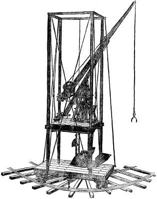
Any arrangement of independent scaffolding may be employed for this system, but that invented specially for the purpose by Mr. Frank West, as shown in Fig. 26 of our engravings, is to be preferred. It not only supplies the necessary scaffold, but also the necessary arrangements for hoisting the slabs, as well as for raising the liquid concrete and depositing it behind the slabs. It is really an independent scaffold, and may be used wherever a light tramway of contractor's rails can be laid, which in crowded thoroughfares would of necessity be upon a staging erected over the footway. The under frame is carried upon two bogie frames running upon the contractor's rail, by which means it is enabled to turn sharp curves, a guide plate inside the inner rail being provided at the curves for this purpose. The scaffold itself consists of a climbing platform made to travel up or down by means of four posts which have racks attached to their faces, and which are fixed to the under frame and securely braced to resist racking strains. A worm gearing, actuated by a wheel on the upper side of the scaffold, causes the scaffold to ascend or descend. A railgrip, made to act at the curves as well as on the straight portions of the rail by being attached to a radial arm fixed to the under frame, assists the stability of the scaffold where required, but the gauge of the rails is altered to render the scaffold more or less stable according to its height. Combined with the same machine, and traveling up and down one of the same posts used for the scaffold, is an improved crane. Its action depends upon the proposition in geometry that if the length of the base of a triangle be altered, its angles, and therefore its altitude, are altered. A portion of the vertical post up and down which the crane climbs forms the base of a triangle, and a portion of the jib, together with the stay, forms the remaining two sides. Hence, by causing the foot of one or the other to travel upward, by means of the worm gearing, the upper end of the jib is either elevated or depressed.
The concrete elevator, which is also combined with the scaffold, consists of a series of buckets carried upon two parallel endless chains passing over two pairs of wheels. On the under frame is fixed a hopper, into which is thrown, either by hand or from a concrete mixer running upon the rails, the material to be hoisted, and from which it gravitates into a narrow channel, through which pass the buckets (attached to the chain) with a shovel-like action. The buckets, a motor being applied to one pair of wheels, thus automatically fill themselves, and on arriving at top are made to tip their contents, and jar themselves, automatically into a hopper by means of a small pinion, keyed to the shaft by which they are attached to the endless chain, becoming engaged in a small rack fixed for that purpose. From the upper hopper the material is taken away to the required destination by means of a worm working in a tube. For varying heights, extra lengths of chain and buckets are inserted and secured by a bolt passed through each end link, and secured by a nut. By using this scaffold, a saving in plant, cartage, and labor is effected. The elevator may also be used for raising any other material besides concrete.
Such is the new system of concrete construction and scaffolding of Messrs. West, which appears to be based on sound and reasonable principles, and to have been thoughtfully and carefully worked out, and which moreover gives promise of success in the future. We may add in conclusion that specimens of the work and a model of a scaffold are shown by Messrs. West at their stand in the Inventions Exhibition.—Iron.
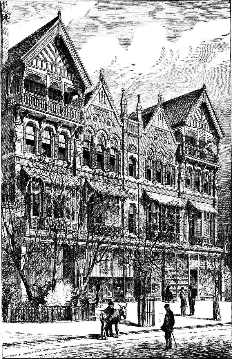
ALBANY BUILDINGS SOUTHPORT. E.W. JOHNSON, ARCHITECT.
1. Cover a flat board, the size of the drawing to be copied, with two or three thicknesses of common blanket or its equivalent.
2. Upon this place the prepared paper, sensitive side uppermost.
3. Press the tracing firmly and smoothly upon this paper, by means of a plate of clear glass, laid over both and clamped to the board.
4. Expose the whole—in a clear sunlight—from 4 to 6 minutes. In a winter's sun, from 6 to 10 minutes. In a clear sky, from 20 to 30 minutes.
5. Remove the prepared paper and pour clear water on it for one or two minutes, saturating it thoroughly, and hang up to dry.
The sensitive paper may be readily prepared, the only requisite quality in the paper itself being its ability to stand washing.
Cover the surface evenly with the following solution, using such a brush as is generally employed for the letter-press: 1 part soluble citrate of iron (or citrate of iron and ammonia), 1 part red prussiate of potash, and dissolve in 10 parts of water.
The solution must be kept carefully protected from light, and better results are obtained by not mixing the ingredients until immediately required. After being coated with the solution, the paper must be laid away to dry in a dark place, and must be shielded entirely from light until used. When dry, the paper is of a yellow and bronze color. After exposure the surface becomes darker, with the lines of the tracing still darker. Upon washing, the characteristic blue tint appears, with the lines of the tracing in vivid contrast. Excellent results have been obtained from glass negatives by this process.—Proc. Eng. Club, Phila.
The following process for making photographic copies of drawings in blue lines on white background was invented by H. Pellet, and is based on the property of perchloride of iron of being converted into protochloride on exposure to light. Prussiate of potash when brought into contact with the perchloride of iron immediately turns the latter blue, but it does not affect the protochloride.
A bath is first prepared consisting of ten parts perchloride of iron, five parts oxalic or some other vegetable acid, and one hundred parts water. Should the paper to be used not be sufficiently sized, dextrine, gelatine, isinglass, or some similar substance must be added to the solution. The paper is sensitized by dipping in this solution and then dried in the dark, and may be kept for some length of time. To take a copy of a drawing made on cloth or transparent paper, it is laid on a sheet of the sensitive paper, and exposed to light in a printing frame or under a sheet of glass. The length of exposure varies with the state of the weather from 15 to 30 seconds in summer to from 40 to 70 seconds in winter, in full sunlight. In the shade, in clear weather, 2 to 6 minutes, and in cloudy weather, 15 to 40 minutes may be necessary. The printing may also be done by electric light. The print is now immersed in a bath consisting of 15 to 18 parts of prussiate of potash per 100 parts of water. Those parts protected from the light by the lines of the drawing immediately turn blue, while the rest of the paper, where the coating has been converted into protochloride by the effects of light, will remain white. Next, the image is freely washed in water, and then passed through a bath consisting of 8 to 10 parts of hydrochloric acid to 100 parts of water, for the purpose of removing protoxide of iron salt.
It is now again washed well in clean water and finally dried, when the drawing will appear in blue on a white background.—Proc. Eng. Club, Phila.
[PROCEEDINGS OF THE ENGINEERS' CLUB OF PHILADELPHIA.]
During the past twenty-five years there have been numerous efforts to introduce fluid fuels as substitutes for coal, for the evaporation of water in boilers, metallurgical operations, and, on a small scale, for domestic purposes.
The advantages claimed for these fuels are: Reduction in the number of stokers, one man being able to do the work of four using solid fuel. Reduction in weight, amounting to one-half with the better classes. Reduction in bulk; for petroleum amounting to about thirty-six per cent., and with the gases, depending on the amount of compression. Ease of kindling and extinguishing fires, and of regulation of temperature. Almost perfect combustion and cleanliness.
Siemens used gas, distilled from coal and burnt in his well known regenerative furnace.
Deville experimented with petroleum on two locomotives running on the Paris and Strassburg Railroad.
Selwyn experimented with creosote in a small steam yacht, and under the boilers of steamship Oberlin.
Holland experimented with water-gas in the furnace of a locomotive running on the Long Island Railroad.
Isherwood experimented with petroleum under the boilers of United States steamers.
Three railroads in Russia are using naphtha in their locomotives, and steamers on the Volga are using the same fuel.
Wurtz experimented with crude petroleum in a reheating furnace at Jersey City.
Dowson, Strong, Lowe, and others have devised systems for the production of water gas.
These experiments, in general, have produced excellent results when considered merely in the light of heat production, but, in advocating their systems, the inventors seem to have overlooked the all-important item of cost.
It is the object of this paper to show the impracticability of such systems when considered from a commercial standpoint, so long as the supply of coal lasts, and prices keep within reasonable limits.
In many cases, authors on the subject have given purely theoretical results, without allowing for losses in the furnace.
The fuels to be considered are anthracite and bituminous coals, crude petroleum, and coal, generator and water gases.
The average compositions of these fuels (considering only the heating agents), as deduced from the analysis of eminent chemists, are:
PERCENTAGE BY WEIGHT.
| C | H | O | CO | CH4 | C2H4 | |
|---|---|---|---|---|---|---|
| Anthracite | 87.7 | 3.3 | 3.2 | |||
| Bituminous | 80.8 | 5.0 | 8.2 | |||
| Petroleum | 84.8 | 13.1 | 1.5 | |||
| Coal gas | 6.5 | 14.3 | 52.4 | 14.8 | ||
| Generator gas | 1.98 | 35.5 | 1.46 | |||
| Water gas | 6.3 | 0.6 | 87.8 | 1.2 |
We will employ the formula of Dulong—
h = 14,500 C + 62,000 (H - O/8)
to compute the theoretical heating powers of these fuels. In the case of methane, CH4, the formula is not true, but the error is not great enough to seriously affect the result. This gives for the combustion of one pound of:
  Anthracite              14,500 Br. Heat Units.
  Bituminous              14,200 "    "     "
  Petroleum               20,300 "    "     "
  Coal gas                20,200 "    "     "
  Generator gas            3,100 "    "     "
  Water gas                8,500 "    "     "
Reducing the above to terms of pounds of water evaporated from 212° F., we have:
POUNDS OF WATER EVAPORATED FROM 212° F.
  Anthracite                               15.023
  Bituminous                               14.69
  Petroleum                                21.00
  Coal gas                                 20.87
  Generator gas                             3.21
  Water gas                                 8.7
The results of experiments show the efficiency of fluid-burning furnaces to be about ninety per cent., while with coal sixty per cent. may be taken as a good figure. The great difference in the efficiencies is due to the fact that fluid fuels require for combustion very little air above the theoretical quantity, while with the solid fuels fully twice the theoretical quantity must be admitted to dilute the products of combustion.
Correcting our previous results for these efficiencies, we have:
POUNDS OF WATER ACTUALLY EVAPORATED FROM 212° F., PER POUND OF FUEL.
  Anthracite                               9.0
  Bituminous                               8.8
  Petroleum                               18.9
  Coal gas                                18.8
  Generator gas                            2.9
  Water gas                                7.8
These figures agree closely with the results of experiments.
We will now consider the subject of cost.
The following cities have been selected, as manufacturing centers, termini of railroads, or fueling ports for steamers.
In the case of petroleum, as it is rarely shipped in the crude state, an approximation is made by adding to the cost at the nearest shipping port the freight charged on refined petroleum, and ten per cent. to cover duties and other charges.
Owing to the difficulty of obtaining prices, in some of the cities, there may be some errors.
                                COSTS. MARCH, 1884.


                   Anthracite        Bituminous        Coal gas
                   per ton of        per ton of        per 1,000
                   2,240 lb.         2,240 lb.         cubic feet.


  New York          $4 00             $4 25             $1 75
  Chicago            5 00              3 50              1 25
  New Orleans        6 00              3 50              3 00
  San Francisco     12 00              7 50              3 00
  London             5 00              3 00              0 75
  Port Natal        12 50             11 00
  Sydney            12 00              7 00
  Valpariso         11 50              7 50


                  Generator         Crude               Water gas
                  gas per 1,000     Petroleum per       per 1,000
                  cubic feet.       bbl. of 42 gal.     cubic feet.


  New York         $0 45             $1 80               $0 50
  Chicago             45              2 00                  50
  New Orleans         45              2 50                  60
  San Francisco       55              2 00                  60
  London              43              2 70                  45
  Port Natal        Ap-               4 00                Ap-
  Sydney            proxi-            4 50                proxi-
  Valparaiso        mation.           3 00                mation.
In calculating the following table the specific gravity of coal gas is taken at 0.4; generator gas at 0.44; water gas at 0.48; petroleum, 0.8.
                POUNDS OF FUEL FOR $1.00.   MARCH, 1884.


                Anthracite. Bituminous. Petroleum. Coal Water Generator
                                                   gas  gas.  gas.


  New York         560         527        156       18   74      76
  Chicago          448         640        142       24   74      76
  New Orleans      374         640        114       10   74      76
  San Francisco    187         299        142       10   62      62
  London           448         747        104       40   82      79
  Port Natal       179         204         71            Ap-     Ap-
  Sydney           187         320         63            proxi-  proxi-
  Valparaiso       195         299         94            mate.   mate.
These figures, multiplied by the actual evaporative powers as calculated, give:
              POUNDS OF WATER EVAPORATED FROM 212° F. FOR $1.


                Anthracite. Bituminous. Petroleum. Coal Generator Water
                                                   gas    gas.    gas.


  New York        5040         4643       2948     338    220     577
  Chicago         4032         5638       2684     451    220     577
  New Orleans     3366         5638       2155     188    220     577
  San Francisco   1683         2634       2684     188    179     484
  London          4032         6581       1966     751    228     640
  Port Natal      1611         1797       1342           Ap-     Ap-
  Sydney          1683         2819       1191           proxi-  proxi-
  Valparaiso      1755         2634       1776           mate.   mate.


                           RELATIVE COSTS.


                Anthracite. Bituminous. Petroleum. Coal Generator Water
                                                   gas    gas.    gas.


  New York         $1 00       $1 08      $1 71   $14 92  $22 90  $8 70
  Chicago           1 00          71       1 50     8 72   18 30   7 00
  New Orleans       1 00          59       1 56    17 90   15 30   5 80
  San Francisco     1 00          64       1 50     8 75    9 40   3 50
  London            1 00          61       2 05     7 16   17 70   6 30
  Port Natal        1 00          90       1 21
  Sydney            1 00          34       1 39
  Valparaiso        1 00          44       1 03
These figures are very much against the fluid fuels, but there may be circumstances in which the benefits to be derived from their use will exceed the additional cost. It is difficult to make a comparison without considering particular cases, but for intermittent heating petroleum would probably be more economical, though for a steady fire coal holds its own.
At the opening meeting for the winter session of the Iron and Steel Works Managers' Institute, held at Dudley on September 12, Mr. R. Smith-Casson in the chair, Mr. B.F. McCallem, of Glasgow, read a paper on "Steel Castings," which developed an interesting discussion upon steel casting practice. Mr. McCallem said that it was thirty years since the first crucible steel castings were made in Sheffield in the general way, and with one exception the method of manufacture was pretty much the same now as at that early date. The improvement was the employment of gas furnaces instead of the old coke holes for melting. Important economies had resulted from this introduction. Where before it required 3 tons of coke to melt 1 ton of steel, the same thing was now done with 35 cwt. of very poor slack. Though it was apparently easy to make crucible steel castings, it was not in reality easy to make a true steel, that was to say, to make a metal that contained only the correct proportions of carbon and silicon and manganese. The only real way to make crucible castings of true steel was to melt the proper proportions of cast steel scrap with the proper amounts of silicon and manganese to produce that chemical composition which was known to be necessary in best castings. It was in consequence of this difficulty that many makers resorted to the addition of hematite pigs. The Bessemer process was used much more extensively upon the Continent than in this country in the manufacture of castings. It seemed likely that Mr. Allen's agitator for agitating the steel in the ladle so as to remove the gases would be taken up largely for open-hearth castings and open-hearth mild steel, as it had a wonderful effect. The Wilson gas producer, working in conjunction with the open-hearth furnace, had recently produced some extremely wonderful results. In some large works, steel was by its aid being melted from slack which was previously absolutely a waste product. The method of making open-hearth steel castings might be varied greatly. The ordinary method generally practiced in this country was a modification of the Terre Noire process. The moulds employed were only of secondary importance to the making of the steel itself. Unless the mould was good, no matter how good the steel was, the casing was spoiled. The best composition which had been found for moulds was that of a large firm in Sheffield, but unfortunately it was rather expensive. A good steel casting ought to contain about 0.3 per cent. carbon and 0.3 per cent. of silicon and from 0.6 to 1 per cent. of manganese. Such a casting, if free from other impurities, would have a strength of between 30 and 40 tons, and on an 8 inch specimen would give an elongation of 20 per cent. or even more. It was possible by the Terre Noire process to produce by casting as good a piece of steel as could be made by any amount of rolling and hammering.
The chairman said that, as they had so high an authority as Mr. McCallem present, Staffordshire men would like to know his opinion upon the open hearth basic system, in which they were greatly interested.
Mr. McCallem said that he believed that the basic process would be worked successfully in this country in the open-hearth furnace before it would be in the converter. At the Brymbo Works, in Wales, he had seen the basic process worked very successfully in the open-hearth furnace; and he was recently informed by the manager that he was producing ingots at the remarkably low sum of 65s. per ton.
The chairman said that some samples which had been sent into Staffordshire from Brymbo for rolling into sheets had behaved admirably. He thought that the Patent Shaft and Axletree Company, at Wednesbury, were at the present moment putting down an open-hearth furnace on the basic process.
The discussion was continued with considerable vigor by Messrs. H. Fisher (vice-president), James Rigby, J. Tibbs, M. Millard, Walker, W. Yeomans (secretary), and others. Several of these gave it as their experience that the best castings contained the most blowholes, and Mr. McCallem accepted the pronouncement, with some slight qualification.
At the recent meeting of the British Association, Don Arturo de Marcoartu read a paper on the above subject.
He stated that he wished to draw special attention to increasing the safety of navigation against storms, fogs, fire, and collisions with wrecks, icebergs, or vessels, and recommending the development of maritime telegraphy. He urged that vessels should be supplied with apparatus to communicate with and telegraph to each other and to the nearest coast the weather and sea passed over by them, and that reports given by vessels should be used as "warnings" more extensively. He wished the mid-Atlantic stations connected by telegraph for the same purpose.
In regard to the use of oil on rough seas, he said that Dr. Badeley in 1857, Mr. John Shields five years ago at Peterhead and last year at Folkestone, the Board of Trade in 1883, and a committee on life saving appliances of the United States had made experiments. The conclusions of the committee were that in deep water oil had a calming effect upon a rough sea, but there was nothing in either source of information which yet answered the question whether or not there is in the force exerted by the wind a point beyond which oil cannot counteract its influence in causing the sea to break. He thought it appeared that oil had some utility on tidal bars; on wrecks, to facilitate the operations of rescue; on lifeboats and on lifebuoys. In regard to icebergs, he thought the possibility of obtaining an echo from an iceberg when in dangerous proximity to a ship should be tried. He advocated the use of automatic sprinklers in the case of fire, the establishment of parabolic reflectors for concentration of sound, and the further prosecution of experiments by Professor Bell in establishing communication between vessels some distance apart by means of interrupted electrical currents. The improvement of navigation, he said, meant an international code of police to improve police rules of navigation; an international code of universal telegraphy for navigation; an international office of meteorology and navigation to collect the studies; experiments on the weather, on the sea, on the casualties; and the discovery by experiment of new apparatus and appliances to diminish maritime disaster.
He had called the attention of two governments to this matter, and he hoped that before long there would be proposed an international congress—such as the postal, telegraph, and sanitary congresses, and the international convention to fix the common meridian—by one of the maritime powers, by which would be founded an international institution to diminish casualties at sea. He recommended a universal system of buoys. The great losses of life and property every year were worthy the devotion of £300,000 by an international institution, which would be much less than the monthly average loss in navigation.
Admiral Pim said that ships were improperly built—some were ten times longer than their beam. There was nothing in the world so ticklish as a ship; touch her in the waist, and down she goes. He believed sailing ships ought not to exceed four times their beam, and steamers certainly not more than six times. He pointed out that a fruitful cause of accidents was the stopping of steaming all at once in the case of impending collision, by which the rudder lost control of the vessel. If constructors looked more to the form of the ships, and got them to steer better, collisions would be avoided.
The Lord Advocate said it had always occurred to him that one great secret of collisions at sea was the present system of lights, which made it impossible for the vessel at once to inform another vessel what it was about. The method of signaling was very crude, and he ventured to say that it was quite out of date when vessels met each other at a rate of speed of 24 to 25 knots. He had, as an amateur, tried a method which he would attempt to explain. His idea was to fit up a lantern on deck, showing an electric light. The instrument would be controlled by the rudder, and the commanding officer of the vessel would be able so to turn it when the helm was put up or down that the light would flash at some distance in front of either bow of the vessel, and thus be a signal to a vessel coming in an opposite direction. When the helm was amidships, the light was shown straight ahead, and could not be moved until the helm was shifted. The direction in which the vessel was going could not by any possibility be mistaken, and it was plain that if the lights from two ships crossed each other, then there was danger. If the lights were clear of each other, then the ships would pass safely.
Sir James Douglass asked if his Lordship had made any experiments.
The Lord Advocate said he had not. The Board of Trade had such a number of inventions on this subject on hand that he supposed they were already disgusted. Besides, he was only an amateur, and left the carrying out of the suggestion to others.
Sir James Douglass said this idea of a lantern did very well for a short distance, but for a long distance it utterly failed. It was very difficult to realize a movement from a distance of over a mile out to sea, and signals were required to be visible for from two to three miles.
The Lord Advocate said his idea depended not upon the object light, but upon the sweep of the light on the water.
Sir James Douglass said all those questions were of the utmost importance to a maritime country. In regard to experiments with oil on troubled water, he had witnessed them, and he had carefully studied all the reports, and had come to the conclusion that they were all very well in a tub of water or a pond, but on the ocean they were utterly hopeless. He would stake his reputation on that. They had been tried in the neighborhood of Aberdeen, and he had prophesied the results before they were commenced. It was utterly hopeless to think that a quantity of oil had the power of laying a storm—all the world could not produce oil enough to bring about that result.
There might be something in maritime telegraphy, and he hoped the experiments of Mr. Graham Bell, in transmitting through two or three mile distances, would come to something. He did not believe in powerful lights. Increase the lights to any very great extent, and a dazzling effect was the result. In regard to sound, he wondered that no more effective alarm was used than the whistle. It was well known that, as the whistle instrument was enlarged, the sound became more and more a roar. He would have ships use all their boiler power in sounding a siren, so that the sound could be heard at a distance of not less than two or three miles in any weather. With such a signal as that there ought to be, not absolute safety, but collisions would be more easily prevented. He was glad to say that a universal system of buoys had been practically arranged, thanks to the Duke of Edinburgh and his committee, so that, as soon as an old system can be changed to a new one, all the buoys would bear one universal language.
Admiral Pim pointed out that a red light would show four miles, while a green light was only visible for two miles and a half, so that, if a green light were seen, it indicated that the two vessels were within two miles and a half of each other.
Sir James Douglass said there was undoubtedly a weakness in regard to these lights; and he held that in the manufacture of lights effect should be given to the difference that existed in the various lights, so that, by making the green light more powerful, it could penetrate as far as the red, and in the same way making the red and green lights proportionately more powerful, so that they would penetrate as far as the white light.
Sir James Douglass said he had seen a parabolic reflector for sound tried, but, unfortunately, the reflector so intensified and focused all the sounds about the vessel and the noise of the sea that the operator could hear nothing but a chaos of sound.
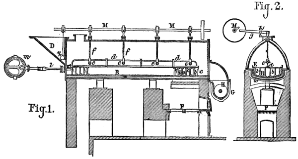
The operation of carbonizing woolen rags for the purpose of obtaining pure wool, through the destruction of the vegetable substances contained in the raw material, maybe divided into two parts, viz., the immersion of the rags in acid, with subsequent washing and drying, and the carbonization properly so called. The first part is so well known, and is so simple in its details and apparatus, that it is useless to dwell upon it in this place. But the second requires more scientific arrangements than those that seem to be generally adopted, and, as carbonization is now tending to constitute a special industry, we think it is of interest to give here a typical plan for a plant of this kind. It will be remarked that this plan contains all the parts in duplicate. The object of this arrangement is to permit of a greater production, by rendering the operation continuous through half of the apparatus being in operation while the other half is being emptied and filled.
Figs. 4 and 5 give plans of the ground floor and first story, and Figs. 1, 2, and 3 give vertical sections. The second story is arranged like the first, and serves as a drier. As we have said, there is a double series of chambers for carbonization, drying, and work generally. These two series are arranged on each side of a central portion, which contains the heating and ventilating apparatus and a stone stairway giving access to the upper stories. The heating apparatus is a hot air stove provided with a system of piping. The rags to be carbonized or the wool to be dried are placed upon wire cloth frames.
The carbonization is effected in the following way: When the heating apparatus has been fired up, and has been operating for about half an hour, the apertures, i, are opened so as to let the air in, as are also those, m, which allow the hot air to pass into the chambers. The hot air then descends from the top of the chamber into the wool or rags, and, becoming saturated and heavier, descends and makes its exit from the chamber through an aperture, n, near the floor, whence it flows to the central chimney. This latter, which is built of brick or stone, contains in its center a second chimney (formed of cast or forged iron pipes) that serves to carry off into the atmosphere the products of combustion from the heating apparatus. The heat that radiates from these pipes serves at the same time to heat the annular space through which the vapors derived from the wool are disengaged.
The air, heated to 40° or 50°, is made to pass thus for several hours, until the greater part of the humidity has been removed. The temperature is then raised to 80° or 90° by gradually closing the apertures that give access to the ventilating chimney. In order that it may be possible to further increase the temperature during the last hour, and raise it to 90° or 120°, an arrangement is provided that prevents all entrance of the external air into the heating apparatus, and that replaces such air with the hot air of the chamber; so that this hot air circulates in the pipes of the stove and thus becomes gradually hotter and hotter. The hot vapors that issue from the lower chamber rise into the upper one, where they are used for the preliminary drying of another part of the materials.
The hot air stove should be well lined with refractory clay, in order to prevent the iron from getting red hot, and the grate should be of relatively wide surface. All the pipes should be of cast iron, and all the joints be well turned. Every neglect to see to such matters, with a view to saving money, will surely lead in the long run to bad results.

PLAN OF WORKS FOR CARBONIZING WOOL. (Scale 1-200.)
The mode of work indicated here is called the moist process. It necessitates the use of a solution of sulphuric acid, but, as this latter destroys most colors, it cannot be used when it is desired to preserve the tint of the woolen under treatment. In this case recourse is had to the dry process, which consists in substituting the vapors of nitric acid heated to 115° or 125° for the sulphuric acid. The arrangement of the rooms must likewise be different. The chambers, which may be in duplicate, as in the preceding case, are vaulted, and are about three yards long by three wide and three high. The rags are put into wire cages that have six divisions, and that are located in the middle of the chamber, where they are slowly revolved by means of gearings. Under the floor are the heating flues, and upon it is a reservoir for holding the vessel that contains the acid to be vaporized. The arrangements for the admission of air and carrying along the vapors are the same as in the other case. Great precaution should be taken to have the flues so constructed as to prevent fire.—Bull, de la Musee de l'Industrie.
According to Mr. D'A. Bernard, it is especially important, in the dry distillation of distiller's wash in a closed vessel, for the production of methyls, ammonia, acetates, and methylamine, that the mass shall be divided as completely as possible, since it then takes but a relatively moderate heat to completely destroy the organic coloring matter contained in the wash. The apparatus shown in Figs. 1 and 2 is based upon this observation.
The wash enters, through the hopper, D, and the valve, z, a long boiler, B, which is heated by the furnace, F, through the intermedium of a waterbath, w. An agitator, E, moves the mass slowly to the other extremity of the boiler, from whence it makes its exit in the form of dust. To the frame, E, are fixed the scrapers, b, and the interrupted pieces, a, in front of which are the hinged valves, c. In the motion of the pieces, a, from right to left, these valves free the apertures thereof and allow the wash to pass, while in the motion from left to right the apertures are closed and the valves push the mass to be evaporated before them.
From any motor whatever, the frame, E, receives a double to and fro motion in a horizontal and vertical direction, the latter of which is produced by the rods, f, which are provided at their lower, forked extremity with rollers, e, over which passes the piece, d, that supports the frame, E. At their upper part the rods, f, pass through the side of the boiler, through the intermedium of stuffing boxes, and are connected by their upper extremities, through a link, with levers, g, that revolve around the point, h. A cam shaft, M, communicates a temporary, alternately rising and descending motion to the levers, g, and the rods f. The same shaft, M, opens and closes the valve, z, of the hopper, D, and thus regulates the entrance of the wash into the boiler. The frame, E, receives its horizontal to and fro motion from the rod, l, which traverses a stuffing-box and is moved by a crank on an eccentric, m. The material in powder derived from the evaporation of the wash is stored at the extremity of the apparatus into a lixiviating vessel, G, provided with a stirrer, H. The salts and other analogous matters are dissolved, and the residuum, which constitutes a carbonaceous mass, is forced out of the apparatus, while the solution passes directly to the refinery, where it is evaporated.
APPARATUS FOR THE EVAPORATION OF ORGANIC LIQUIDS.
In manufactories where no refining is done, the crude potassa in powder is pushed on to a prolongation of the apparatus which is cooled by means of water, and is removed from time to time with shovels by the workmen, so that the orifice of the boiler remains constantly covered externally by the mass, and that the air cannot re-enter the apparatus.
The gases disengaged during the operation pass into a cooler, where they condense into a liquid which contains ammonia and methylamine. The non-condensable part of the gases is burned in the furnace of the manufactory.
In the American Court of the Inventions Exhibition, London, we find a leveling machine for sheet metals exhibited by Mr. J.W. Britton, of Cleveland, Ohio, and which we illustrate.
This apparatus is intended to supersede the cold rolling of plates in order to take the buckle out of them. The sheets are clamped in the jaws or grips shown, and the stretch is effected by means of a hydraulic ram connected directly to the nearest pair of jaws. The power is obtained by means of a pair of pumps run through spur-gearing by the belt pulleys shown. The action of the machine puts a strain on those parts of the plates which are not "bagged" or buckled, and this causes the surface to extend, the slack parts of the plate not being subject to the same stretching action. The machine shown is designed to operate on sheet iron from No. 7 to No. 30 gauge, and up to 36 in. wide, the limit for length being 120 in. About a dozen sheets can be operated on at once. The machine appears to have met with considerable success in America, and has been used for mild steel, iron, galvanized or tinned sheets, copper, brass, and zinc. The details of this machine are given in Figs. 1 to 8. Figs. 1 and 2 are a plan and side elevation of the bed of the machine, showing the position of the hydraulic ram. Fig. 3 shows the bars used for holding the back jaws in position, with the holes for adjusting to different lengths of the plates. Fig. 4 is a back view and section of the crosshead and one of the bolts that connect the moving grip with the hydraulic ram. Fig. 5 gives a plan and cross section of the back grip, and Fig. 6 is a back elevation of the same, with a front view and section of the gripping part. Fig. 7 shows the gear by which the jaws are opened and closed.
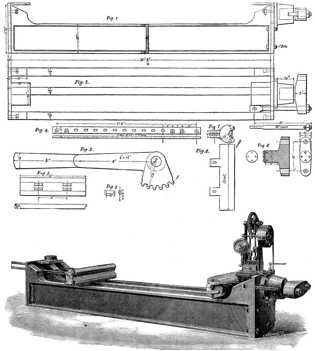
BRITTON'S PLATE STRAIGHTENING MACHINE.
Among the numerous arrangements that have been devised for drawing circles in diagrams, sketches, etc., one of the simplest is doubtless that which is represented in the accompanying figure, and which is known in England as the "scholar's compasses." It consists of a socket into which slides a pencil by hard friction, and to which is hinged a tapering, pointed leg. This latter and the pencil are held at the proper distance apart by means of a slotted strip of metal and a binding screw. When the instrument is closed, as shown in the figure to the left, it takes up but little space, and may be easily carried in the pocket without the point tearing the clothing, as the binding screw holds the leg firmly against the pencil.
The mode of using the apparatus is so well shown in the figure to the right that it is unnecessary to enter into any explanation.—La Nature.
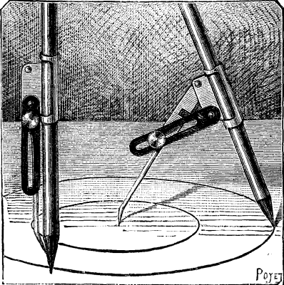
THE SCHOLAR'S COMPASSES.
In scientific researches in the domain of physics we often meet with the following problem: Being given any function whatever, y = f(x), to find a curve whose equation shall be
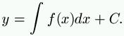
Let us take an example that touches us more closely; let us suppose that we know an induced current, and that we can represent it by a curve y=f(x). The question is to find the inductive current, that is to say, the curve represented by the equation
The apparatus called an integraph, constructed by Messrs. Napoli and Abdank-Abakanowicz, is designed for solving this problem mechanically, by tracing the curve sought. Let us take another example from the domain of electricity, in order to better show the utility of the apparatus; let us suppose that we have a curve representing the discharge of a pile or of an accumulator. The abscisses represent the times, and the ordinates the amperes. The question is to know at every moment the quantity of coulombs produced by the pile. The apparatus traces a curve whose ordinates give the number of coulombs sought. We might find a large number of analogous applications.
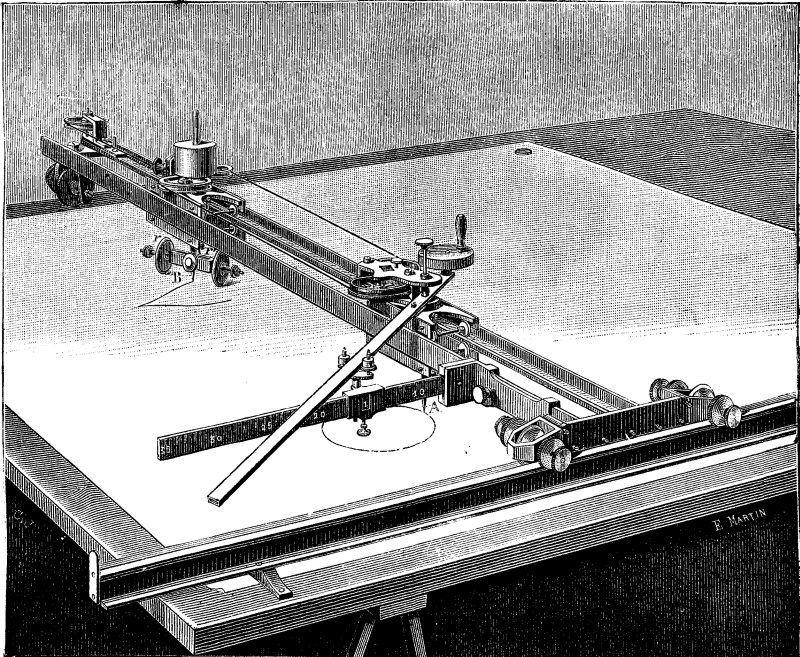
THE INTEGRAPH.
The apparatus is represented in the accompanying figure. An iron ruler, I, parallel with the axis of the X's, is fixed upon a drawing-board, and is provided with a longitudinal groove in its upper surface. In this groove move two rollers, which, in the center of the piece that connects them, carry two brass T-squares that are parallel with each other and at right angles with the first, or parallel with the axis of the Y's. Between these two rulers move two carriages, the first of which (nearest the axis of the X's) carries a point, A, designed to follow the contour of the curve to be integrated, while the second, which is placed further away, is provided at the center with a drawing-pen, A', whose point is guided by two equidistant wheels, R, R', that roll over the paper in such a way as to have their plane parallel with a given straight line, and that have always a direction such that the tangent of the point's angle with the axes of the X's is constantly proportional to the ordinate of the primitive curve.
The carriages are rendered very movable by substituting rolling for a sliding friction of the axes. To this effect, the extremities of the axes of the wheels that support and guide them are made thin, and roll over the plane surface of recesses formed for the purpose in the lateral steel surfaces of the carriages, while the circumference of the wheels rolls in grooves along the two T-squares.
These latter are, on the one hand, carried by rollers that run in the groove of the iron, I, and, on the other, by a single roller that runs over the paper. At right angles with one of these bars is fixed a divided ruler, through one point of which continually passes a third ruler, whose extremity pivots upon the point, A, of the first carriage.
When the divided ruler is placed upon the axis of the X's, and the point, A, of this carriage is following the contours of the figure to be integrated, the tangent of the angle made by the inclined ruler with the axis of the X's will be proportional to the ordinate of the figure. The wheels, R and R', of the drawing-pen, A', of the second carriage must move parallel with this ruler. In order to obtain such parallelism, we employ a parallelogram formed as follows: Two gear-wheels of the same diameter are fixed upon the ruler that ends at the point, A, of the first carriage, and their line of centers is parallel with the latter. The second carriage likewise carries two drums equal in diameter to those of the toothed wheels. These are fixed, and their line of centers must remain constantly parallel with the line of centers of the gear-wheels, and consequently with the straight line which passes through the point, A. This parallelism is obtained by means of a weak steel spring, or of a silken thread passing over the four wheels, the two first of which (the gear-wheels) hold it taut by means of a barrel and spring placed in the center of one of them.
The edge of the wheels, R, R', of the second carriage prevents the latter from giving way to the traction of the threads, permitting it thus to move only in the direction of their plane.
It will be seen that by this system two of the sides of the parallelogram are capable of elongating or contracting through the unwinding and winding of the silken thread on the drums of the two cog wheels, which latter, gearing with each other, allow of the escape of but the same length of the two threads.
It will be observed that in this system integration is effected by forcing the pen to follow a certain direction, and that consequently the curve does not depend upon the dimensions of the different parts of the apparatus.—La Lumiere Electrique.
The apparatus represented in the accompanying cuts is designed for the manufacture of gaseous beverages, and is of Messrs. Boulet & Co.'s make. Fig. 1 represents the apparatus complete, with gasometer and bottling machine. Fig. 2 gives a vertical section of the apparatus properly so called, including the producer, the purifier, and the saturator, all grouped upon a cast-iron column.
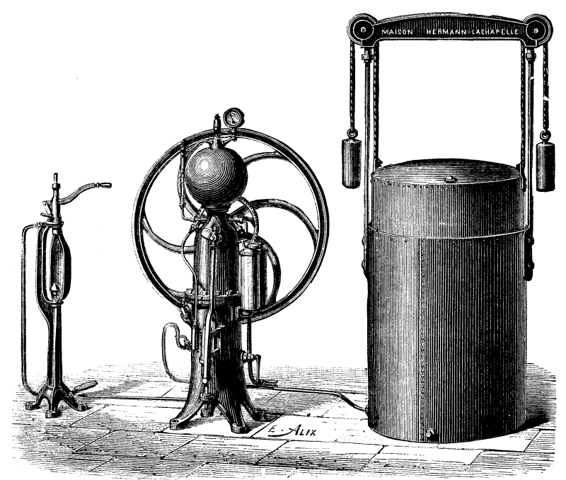
FIG. 1. APPARATUS FOR MANUFACTURING GASEOUS BREEZES.
The producer, A, is designed to receive the sulphuric acid and carbonate of lime. A mixer, F, revolves in the interior of this, and effects an intimate admixture of the lime and acid without the necessity of the former being pulverized beforehand. The carbonate of lime (usually in the form of chalk) is introduced directly into the producer through the aperture, K, while the acid contained in the receptacle, B, at the side of the column and above the producer flows put through a curved pipe in the bottom. The flow is regulated by the valve, C. The receptacle, B, is lined with platinum. As soon as the acid comes into contact with the carbonate, there occurs a disengagement of carbonic acid gas, which flows directly through the pipe, F, into the purifier at the upper part of the column. From thence the gas passes into a third washer, D, of glass. When thoroughly washed, it flows through the pipe, L, into the gasometer, which is of galvanized iron, and is very carefully balanced.
The saturator, which is the most important part of the apparatus, comprises a pump, a feed reservoir, and a sphere. The pump, which is of bronze, is placed at the side of the column, at the lower part (Fig. 1). This sucks up the gas stored in the gasometer and the water contained in the reservoir, and forces them into the sphere. This latter is of bronze, cast in a single piece, and the thickness of its sides prevents all danger of explosion. It is silvered internally, and provided with a powerful rotary agitator that favors the admixture of the water and gas.
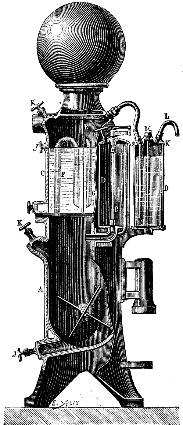
FIG. 2.
The apparatus it rendered complete by a bottling machine, which is placed either on a line with the apparatus or in front of it. This machine is connected directly with the sphere by a block-tin pipe.—Chronique Industrielle.
Among the numerous apparatus that have been devised for determining the power of powder, those designed for military purposes are the ones most extensively used. Up to the present, very few experimental apparatus have been constructed for civil uses, although such are no less necessary than the others. Mr. D'O. Guttman has examined the principal types of dynamometers with respect to their use for testing explosive materials, and, after ascertaining wherein they are defective, has devised an apparatus in which the principle is the same as that employed by Messrs. Montluisant and Reffye at Meudon, that is to say, one in which the force of the powder is made to act upon a lead cylinder fixed in a conical channel. Mr. Desortiaux objects that in this system, when it is employed with charges for cannons, the action has already begun when only a portion of the powder is burned. To this, Mr. Guttman responds that his apparatus operates only with small charges (300 grains), which practically inflame simultaneously in every part when the igniting is done in a closed space. In order that the force may not be made to act in one direction only, the inventor uses two leaden cylinders. His apparatus is shown in the accompanying Figs. 1, 2, and 3. It consists of a median piece, a, and of two heads, b, of an external diameter of four inches. These pieces are of tempered Bessemer steel. The two heads are four inches in length, one inch of which is provided with a screw thread. Each of them contains an aperture, c, 1.34 inches wide below, 1.3 inches wide above, and 1.18 inches deep. This aperture is followed by another and conical one, d, 1.38 inches deep, and 0.4 inch wide at its narrowest end, and finally by another one, e, 0.4 inch wide, which runs to the exterior. The median piece, a, is 4 inches long. It is provided at the two sides with nuts, between which there is a cylindrical space, f, 1.8 inches long, designed to receive the charge. The inflaming plug, g, is screwed into the exact center of the median piece, a, which it enters to a depth of one inch. Into the space that still remains free is screwed a plug, h. The lower surface of the plug, g, contains a hollow space, 0.6 inch wide and deep. This hollow is prolonged by another one, 0.24 inch wide, and contains a valve, i, which has a play of about 0.08 inch. The three parts are connected by a key which passes into the holes, x, and are rendered tight by copper rings, y.
When it is desired to charge the apparatus, a leaden cylinder, 1.34 inches long and 1.3 inches in diameter, is placed in one of the heads, and the median piece is so screwed that it can be made still tighter by a few turns. Then a steel plate, k, 1.3 inches wide by 0.2 inch thick, is placed against the cylinder, and against this plate again is placed a cardboard disk, 1.34 inches wide by 0.4 inch thick. This completely closes the hollow space. The steel plates and heads are marked with the figures 1 and 2, which, through the pressure, are impressed upon the leaden cylinders. Then the charge of powder, weighing exactly 300 grains, is introduced, and a new cardboard disk, a steel plate, and a leaden cylinder are inserted, and the second head is screwed up. The apparatus is now ready to operate. An ordinary priming is placed on the pyramid, h, and the plug with the valve is screwed down in such a way that the latter shall have a little play. By means of a hammer, m, a smart blow is given the valve i, and this detonates the priming, and causes an explosion of the charge. The gases make their exit through the pyramid, h, and lift the valve and press it against the plug, so that their escape is effectually prevented. In fact, the explosion takes place without noise. A slight whistling, only, indicates that the capsule has not missed fire, and that the apparatus may be immediately opened, the gases having condensed in the interior. It is well, however, to place the closed apparatus in water, in order that the residua that have entered the threads of the screw may become detached, and that the apparatus may be opened easily. Although there is no danger in standing alongside the apparatus, it is much better to spring the hammer by means of a cord of a certain length, since the valve and especially the pyramid gradually burn and may be thrown out. With some kinds of powder the pyramid rapidly melts, and must be frequently replaced.

APPARATUS FOR MEASURING THE FORCE OF EXPLOSIVES.
The two cones of lead obtained are then measured to 0.004 of an inch by means of a gauge (Fig. 3).
The inventor has made numerous experiments with his apparatus, and thinks it permits of determining the total force developed by powder very perfectly.
For obtaining anhydrous or very concentrated vinegar directly from pyrolignite of lime or other acetates by a single distillation, Mr. D. Sandmann, of Charlottenburg, employs the apparatus shown in the accompanying engraving. It consists of a double-bottomed copper or enameled iron boiler, A, arranged for being heated by steam, and the upper part of which is protected against the action of the acid vapors disengaged during distillation by a lining of refractory clay. The stone cover, B, is provided with an aperture, b, through which the boiler is filled. The steam pipe, k, is inclosed in a second pipe, f, provided with radii. This tube serves as a stirrer; and is set in motion by means of a pulley, g. The tube, c, is connected with a worm, h, and the tube, d, which is provided with a valve, leads to the second boiler, C. The head, D, which acts, by reason of its internal arrangement, as a dephlegmator, is of enameled iron, and is provided with a thermometer, f, and an aperture, p. Above the spirals of the worm, e, are placed strips of glass, the free intervals between which are filled in with pieces of glass, porcelain, or any other material not attackable by acids. The arrangement is such that the rising vapors can regularly and without obstruction traverse these materials of wide surface. The condensed liquid falls back into the lower part of the boiler. The worm, e, debouches into a cooler, F, fed with water through the cock, n.
At the bottom of the boiler, A, there is fixed a tubulure, r, closed by a lever, s, and having a fastening device, o. This tubulure permits of emptying the boiler into the reservoir, L.
A like arrangement is found in the boiler, C. The valves, V, serve to introduce steam for heating into the double bottoms of the two boilers. The water of condensation flows out through the tubes, u. The water for cooling enters the coolers, F, J, and Z, through the cocks, n, and flows out through the tubes, v.
The acetate, previously crushed, is placed in the boiler, A, and the quantity of acid necessary to decompose it is added. The mass is afterward mixed with care by means of the stirrer, and the distillation may then proceed at once.
The vapors of acetic acid that are disengaged enter the boiler, C, through the tube, d, and are kept hot by the steam. In the head, D, they are separated into two portions, viz., into concentrated acetic acid, which condenses by reason of its high boiling point, and into steam, which distills and carries along but a very small amount of acetic acid. This steam passes through the pipe, G, into the worm, H, condenses, and afterward flows into the vessel, N.
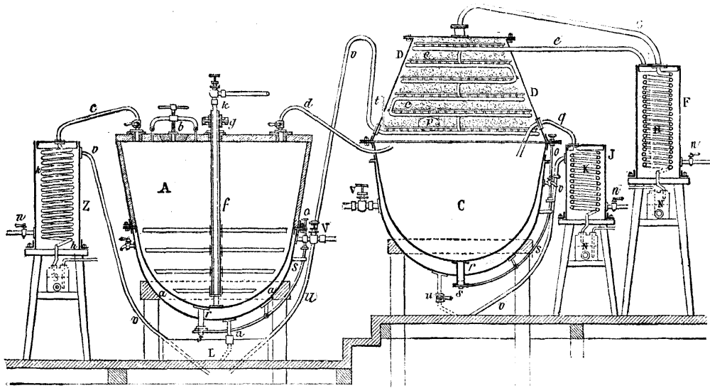
APPARATUS FOR THE MANUFACTURE OF VINEGAR.
The acetic acid that accumulates in the boiler, C, must be again vaporized and treated until it no longer gives off any steam at all through the pipe, G. The amount of cooling water admitted into the worm, e, that traverses the head, D, is regulated according to the degree of concentration it is desired to give the acid. As soon as the steam can no longer be separated in the boiler, C, and temperature has reached 118 degrees, the anhydrous acetic acid is distilled through the tube, g, and received in the cooler, K, wherein it condenses. When the contents of the boiler, A, have been distilled to dryness, the tube, d, is closed and the cock of the tube, c, is opened. After this, steam is injected directly through the tube, k, in order to distill the acetic acid that still remains in the residuum, and which passes thus through the tube, e, into the worm, h, and flows into the two-necked bottle, S.
There may be added to the boiler, C, certain materials for purifying the acetic acid, such as permanganate of potassa or acetate of soda, so as to obtain an absolutely pure article.—Dingler's Polytech. Journal.
We illustrate the field kitchens of Captain J.C. Baxter, R.E., in the Inventions Exhibition. Figs. 1 to 3 represent Captain Baxter's Telescopic Kitchen, both open for use and packed up for traveling. These kitchens, which are on an entirely new principle, consist of from three to five annular kettles, either circular or elliptical, which are placed one on another, and the fire lighted inside the central tube. The kettles are built up on the top of the outer case in which they are carried, the central tube being placed over the grate in the lid. A small iron stand, supporting an ordinary pot, is placed on the top. When packed up, the annular kettles fit or nest into each other, and into the outer case; the iron stand packs inside the innermost kettle, and the top pot is placed on the outer case, being secured by a strap. This form of kitchen is intended for the use of officers, both regular and volunteer, and for officers' and sergeants' messes on active service or in camp. They are also suited for travelers, explorers, colonists, boating, shooting, and fishing parties, and in fact for all who may require to cook in the open air. Figs. 4 to 6 represent the kitchen of the field service pattern with conical kettles, while Figs. 7 and 8 represent the same pattern with elliptical kettles. These kitchens consist of five annular vessels, either circular or elliptical, which are placed one upon another, and the fire lighted in the central tube or flue. A small iron stand, supporting an ordinary pot or kettle, may be placed on the top as in the other set. A small hole, 18 inches long, 6 inches deep, and of the same width as the central tube of the annular kettles, may be made for an ashpit, or the kitchen may be raised a few inches from the ground on stones or turf. The annular vessels may be made cylindrical or conical; in the latter case they will fit or nest into one another, and save space when not in use. They may be made circular or elliptical. Those intended for cavalry are provided with straps to attach them to the saddle. This form of kitchen is intended for the use of troops on active service, or in camp or barracks, workhouses prisons, schools, and soup kitchens; also for cooking food for cattle and hounds; and for all who may require to cook and distribute quickly large quantities of food, soup, or tea, or to heat water rapidly at a small cost. The manufacturers are M. Adams & Son, London.—Iron.
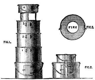
FIG. 1.-FIG. 3. FIELD KITCHENS.
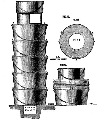
FIG. 4.-FIG. 6. FIELD KITCHENS.
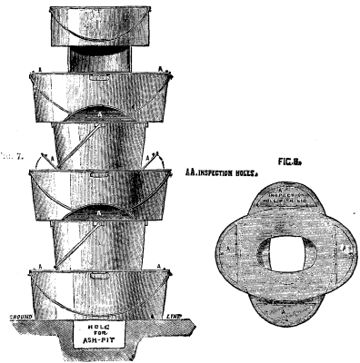
FIG. 7.-FIG. 8. FIELD KITCHENS.
In Germany extensive use is made of a cop-winding machine in which the wooden spindle consists of a cone moved by a screw, and the position of which is horizontal. Fig. 1 shows the primitive type of the German apparatus, in which the cone that forms the cop is set in motion by a horizontal screw. It is at first the greater diameter of the cone that moves the tube, and permits the thread to accumulate beneath the narrow extremity. But, as soon as a core of thread has been formed, it is in contact with the entire surface of the cone, and thus revolves with a mean velocity until it is finished.
In the new model (Fig. 2) the arrangement is different. Here A is the paper tube, with wooden base, to which it is freely attached, and C is the cone that moves over the screw, D. The thread passes into a groove which makes one revolution of the cone, and from thence over the paper tube, where it receives the form of a cop by reason of the transverse motion of the cone upon the screw. This transverse motion is at first prevented by the click, F, which falls into the teeth of the ratchet-wheel fixed behind the cone. The shaft revolves continuously, but has, at the same time, a to and fro motion in the direction of its axis, so as to cause the thread to move forward constantly and form a cop. This to and fro motion is obtained by means of a lever and a sleeve, I, the wheel, H, of the shaft being set in motion by the pinion, J, actuated by the transmission of the machine. As the spindle advances, a core is formed; the click, F, is then pushed backward, and the cone is kept in motion by the thread until the cop is finished.
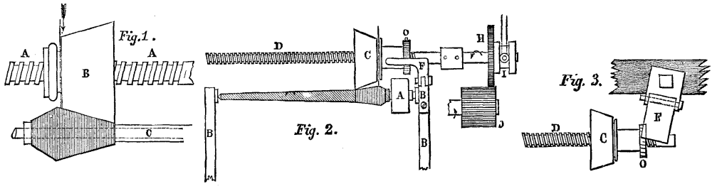
A NEW COP-WINDING MACHINE.
Preference is usually given to the horizontal model; but the system may likewise be applied to a vertical spindle, and the arrangement in this case is simpler, as shown in Fig. 3. A rotary motion of the shaft is useless here, as the click, F, acts in an oblique position upon the ratchet-wheel, O, and pushes it by reason of the to and fro motion of the screw.
[Continued from SUPPLEMENT, No. 513, page 8191.]
The name of Dr. Boucherie is generally applied to the process, which he invented and extensively applied, of preparing wood by forcing a solution longitudinally through the pores of the wood by means of hydraulic pressure. As, however, he also patented the use of sulphate of copper, and his name became attached to the use of that antiseptic, it will be convenient here to classify experiments made with that substance under this head.
Dr. Boucherie was a distinguished French chemist, who between 1836 and 1846 made many elaborate researches and experiments upon the preservation of timber. He tried many substances, and at first recommended the use of pyrolignite of iron, but subsequently used sulphate of copper, which he considered more effective.
His first experiments were conducted by vital suction, that is, by tapping the living tree, and allowing the ascending sap to carry up a preserving solution. This was not found to give uniform or satisfactory results, and Dr. Boucherie then invented the process which bears his name. This was practiced either by applying a cap to the end of a freshly cut log, through which the solution was allowed to flow by pressure, or by sawing a log nearly through in the middle, raising it at the center slightly, so as to open the joint, placing a strip of tarred rope or a rubber band just inside the periphery of the cut log, and letting it spring back, so as to form a tight joint by pressing upon the rope or band. An auger hole bored diagonally into the cavity so formed then served to admit the solution under pressure.
This process, applied with a solution of about one pound of sulphate of copper to one hundred pounds of water, has been extensively applied in France for many years, with satisfactory results. It was found, however, that to be successful it must be applied to freshly cut trees in the log only, and that this involved so much delay, moving about, waste, and annoyance, that it has now been abandoned. These difficulties would be still greater in this country, and in the Northern States the process could not be applied at all during the winter (or season for cutting down trees), as the solution would freeze.
On this page is a list of the experiments which your committee have been able to learn about, as having been made with sulphate of copper in this country.
RECORD OF AMERICAN EXPERIMENTS.
SULPHATE OF COPPER, OR BOUCHERIE.
--+--------------+----+--------+----------+----------+----------+---------------
  |              |    |        | Material |Subsequent|          |
No|   Locality   |Year|Process.| Treated. | Exposure.| Results. |  Authority.
--+--------------+----+--------+----------+----------+----------+---------------
 1|Chili, S.A.   |1857|Boucher.|Poplar    |R.R. track|Favorable |W.W. Evans
  |              |    |        |  ties    |          |          |
 2|Cleveland, O  |1870|Thilmany|Ties      | "     "  |Favorable |J.R. Conrad
  |              |    |        |          |          | to 1875  |
 3|Washington    |1872|   "    |Paving    |Laboratory|Unfavor.  |W.C. Tilden
  |              |    |        |  blocks  |          |          |
 4|Pensacola     |1874|   "    |Live oak  |Teredo    |Failure   |W.H. Varney
  |              |    |        |          |          |          |
 5|Charleston, SC|1875|   "    |Pine block|  "       |   "      |Q.A. Gillmore
  |              |    |        |          |          |          |
 6|San Francisco |1876|   "    | "     "  |  "       |   "      |C.S. Stewart
  |              |    |        |          |          |          |
 7|Milwaukee     |1876|   "    | "     "  |Pavement  |Favorable,|Schlitz Bg.
  |              |    |        |          |          | 1882     |  Co.
 8|Norfolk, Va.  |1876|   "    |Hackmatack|Teredo    |Failure   |P.C. Asserson
  |              |    |        |          |          |          |
 9|Charlestown,  |1877|   "    |Various   |Laboratory|Favorable |J.F. Babcock
  | Mass         |    |        |          |          |          |
10|Wabash R.R.   |1877|   "    |Ties      |R.R. track|Unfavor.  |R.A. Houghton
  |              |    |        |          |          |          |
11|Wabash R.R.   |1878|   "    | "        | "     "  |   "      |W.S. Lincoln
  |              |    |        |          |          |          |
12|New York,     |1879|   "    | "        | "     "  |   "      |C. Latimer
  | Pennsylvania,|    |        |          |          |          |
  | and Ohio R.R.|    |        |          |          |          |
13|Lake Shore and|1879|   "    | "        | "     "  |   "      |R.A. Houghton
  | Michigan     |    |        |          |          |          |
  | Southern R.R.|    |        |          |          |          |
14|Cleveland and |1879|   "    | "        | "     "  |   "      |C. Latimer
  |Pittsburg R.R.|    |        |          |          |          |
15|Charlestown,  |1879|   "    |Spruce    |Sidewalk  |Success   |S.G. White
  | Mass         |    |        |  plank   |          | to 1882  |
16|Baltimore and |1879|   "    |Ties      |R.R. track|Too recent|J.L. Randolph
  | Ohio         |    |        |          |          |          |
17|Hudson River  |1869|Hamar   | "        | "     "  |Success   |E.W. Vanderbilt
  | R.R.         |    |        |          |          |          |
18|St. Louis     |1882|Fladd   | "        | "     "  |Too recent|H. Fladd
--+--------------+----+--------+----------+----------+----------+---------------
The first experiment was carried out by Mr. W.W. Evans, on the Southern Railway of Chili, in 1857, and he informs your committee that in 1860, when he left that country, the ties were still good and in serviceable condition.
We give herewith, in Appendix No. 16, an interesting letter from Mr. E. Pontzen to Mr. Evans, on the subject of the Boucherie process.
Experiments Nos. 2 to 16, inclusive, were all tried with various modifications of the sulphate of copper process as introduced by Mr. W. Thilmany in this country. They date back to 1870 (experiment No. 2), when Mr. Thilmany was working and recommending the methods of vital suction and of the Boucherie hydraulic pressure system. After describing the foreign methods of injection with sulphate of copper, he states in his first pamphlet (1870): "This process resulted very satisfactorily, but it was found that the sulphate of copper became very much diluted by the sap, and when the same liquid was used several times, the decaying substance of the sap, viz., the albumen, was reintroduced into the wood, and left it nearly in its primitive condition."
He accordingly proposed a double injection, first by muriate of barytes, and, secondly, by sulphate of copper, forced through by the Boucherie process, and it is presumed that the ties of 1870, in experiment No. 2, which showed favorable results when examined in 1875, were prepared by that process.
Subsequently Mr. Thilmany changed his mode of application to the Bethell process of injecting solutions under pressure in closed cylinders, and probably the paving blocks for experiment No. 3 were prepared in that way. The chemical examination of them by Mr. Tilden, however, showed the "saturation very uneven; absorptive power, high; block contains soluble salts of copper, removable by washing."
It was expected that the double solution, by forming an insoluble compound, would prove an effective protection against the teredo. Experiments Nos. 4, 5, 6, and 8, however, proved the contrary to be the fact.
The process, when well done, gave moderately satisfactory results against decay. A pavement laid in the yard of the Schlitz Brewing Company, in Milwaukee (experiment No. 7), was sound in 1882, after some six years' exposure. A report by Mr. J.F. Babcock, a chemist of Boston (experiment No. 9), indicated favorable results, and the planks in a ropewalk at Charlestown (experiment No. 15), laid in 1879, were yet sound in 1882.
The experiments on railroad ties (Nos. 10, 11, 12, 13, 14, and 16), however, did not result satisfactorily. They seemed favorable at first, and great things were expected of them; but late examinations made on the Wabash Railroad, on the New York, Pennsylvania, and Ohio, and on the Cleveland and Pittsburg Railroad, have shown the ties to be decaying, and the results to be unfavorable.
This applies to the sulphate of copper and barium process. Mr. Thilmany has patented still another combination, in which he uses sulphate of zinc and chloride of barium, which has been noticed under the head of burnettizing.
Experiment No. 17 was tried on the Hudson River Railroad. It consisted of 1,000 sap pine ties, which had been impregnated in the South, by the Boucherie process, with a mixture of sulphate of iron and sulphate of copper, under Hamar's patent. These ties were laid in the tunnel at New Hamburg, a trying exposure, and when examined, in 1882, several of them were still in the track. The process, however, was found to be so tedious that it was abandoned after a year's trial, and has not since been resumed.
In 1882 Mr. H. Fladd, of St. Louis, patented a method which is the inverse of the Boucherie process (experiment No. 18). To the cap fastened to the end of a freshly cut log he applies a suction pump, and placing the other end into a vat, filled with the desired solution, he sucks up the preserving fluid through the pores or sap cells of the wood.
Quite a number of experimental ties have been prepared in this way, with various chemical solutions, chief of which was sulphate of copper, and there is probably no question but that the life of the wood will be materially increased thereby.
Whether the process will prove more convenient and economical than the original Boucherie process can only be determined by practical application upon an extensive scale.
A considerable number of modifications and appliances for working the Boucherie process have been patented in this country; but none of them seems to have come into practical use, probably because of the necessity for operating upon freshly cut logs, and the inconvenience of such applications.
The table on this page gives a record of various experiments with miscellaneous substances.
RECORD OF AMERICAN EXPERIMENTS—MISCELLANEOUS.
--+------------+----+-----------+---------+----------+---------+---------------
  |            |    |           |Material |Subsequent|         |
No| Locality   |Year| Process.  | Treated.| Exposure | Results.|  Authority.
--+------------+----+-----------+---------+----------+---------+---------------
 1|Chestnut    |1839|Earle's    |Hemlock  |Paving    |Failure  |S.V. Beuet
  | Street,    |    |           | blocks  |          |         |
  | Philadelpha|    |           |         |          |         |
  |            |    |           |         |          |         |
 2|Watervliet  |1840|  "        |Oak      |Gun       |   "     |    "
  | Arsenal    |    |           | timber  | carriage |         |
  |            |    |           |         |          |         |
 3|Delaware &  |1840|  "        |Rope     |Fungus    |Favorable|    "
  | Hudson     |    |           |         | pit      |         |
  | Canal      |    |           |         |          |         |
  |            |    |           |         |          |         |
 4|Philadelphia|1840|Lime bath  |Pine     |Railroad  |Unfavor. |M. Coryell
  | & Columbia |    |           |stringers| track    |         |
  | Railroad   |    |           |         |          |         |
  |            |    |           |         |          |         |
 5|Boston &    |1844|Sulphate   |Ties     |   "      |   "     |I. Hinckley
  | Providence |    | of iron   |         |          |         |
  | Railroad   |    |           |         |          |         |
  |            |    |           |         |          |         |
 6|Belvedere   |1850|Salt       |Hemlock  |   "      |   "     |M. Coryell
  | Railroad   |    |           |         |          |         |
  |            |    |           |         |          |         |
 7|Baltimore   |1850|Lime       |Ties     |   "      |   "     |J.L. Randolph
  | & Ohio     |    |           |         |          |         |
  | Railroad   |    |           |         |          |         |
  |            |    |           |         |          |         |
 8|Rochester   |1852|Payenizing |Ties     |   "      |   "     |T. Hilliard
  |            |    |           |         |          |         |
 9|Germantown, |1855|Charring   |Fence    |Fence     |Favorable|G. McGrew
  | Ind.       |    |           | posts   |          | 1879    |
  |            |    |           |         |          |         |
10|Pottsville, |1857|Pyrolig'ite|Timber   |Railroad  |Unfavor. |H.K. Nichols
  | Pa.        |    | of iron   |         | sills    |         |
  |            |    |           |         |          |         |
11|Erie Railway|1858|Boring     |  "      |Bridges   |Favorable|H.D.V. Prait
  |            |    |           |         |          |         |
12|Galveston   |1867|Casing     |Piles    |Bridge    |Failure  |W.H. Smith
  |            |    |           |         |          |         |
13|New York    |1868|Beerizing  |Lumber   |Signs     |Doubtful |S. Beer
  |            |    |           |         |          |         |
14|Wyoming     |1868|Natural    |Ties     |Railroad  |Preserved|J.
  | Territory  |    | soil      |         | track    |         | Blinkinsderfer
  |            |    |           |         |          |         |
15|Chicago,    |1870|Foreman-   |Timber   |Steamboat |Favorable|M.B. Brown
  | Ill.       |    | izing     |         |          | 1879    |
  |            |    |           |         |          |         |
16|Illinois    |1871|    "      |Ties     |Railroad  |Failure  |L.P. Morehouse
  | Central    |    |           |         | track    |         |
  | Railroad   |    |           |         |          |         |
  |            |    |           |         |          |         |
17|St. Louis   |1871|    "      |Shingles |Roof      |   "     |F. De Funiak
  |            |    |           |         |          |         |
18|Memphis &   |1871|    "      |Ties     |Railroad  |   "     |F. De Funiak
  | Charleston |    |           |         | track    |         |
  |            |    |           |         |          |         |
19|Washington, |1871|Tripler    |Paving   |Laboratory|   "     |W.C. Tilden
  | D.C.       |    |           | blocks  |          |         |
  |            |    |           |         |          |         |
20|   "        |1872|Samuel     |   "     |    "     |   "     |    "
  |            |    |           |         |          |         |
21|   "        |1872|Taylor     |   "     |    "     |   "     |    "
  |            |    |           |         |          |         |
22|   "        |1872|Waterbury  |   "     |    "     |   "     |    "
  |            |    |           |         |          |         |
23|   "        |1872|Sulphate   |   "     |Pennsyl-  |   "     |J.A. Partridge
  |            |    | of iron   |         | vania Ave|         |
  |            |    |           |         |          |         |
24|   "        |1872|Samuel     |   "     |F. Street |   "     |    "
  |            |    |           |         |          |         |
25|   "        |1872|Samuel     |   "     |16th St.  |   "     |    "
  |            |    |           |         |          |         |
26|Norvolk, Va.| -  |Red lead   |Pine and |Teredo    |   "     |P.C. Asserson
  |            |    |           | oak     |          |         |
  |            |    |           |         |          |         |
27|   "        | -  |White zinc |   "     |  "       |   "     |    "
  |            |    |           |         |          |         |
28|   "        | -  |Tar and    |   "     |  "       |   "     |    "
  |            |    | plaster   |         |          |         |
  |            |    |           |         |          |         |
29|   "        | -  |Kerosene   |   "     |  "       |   "     |    "
  |            |    |           |         |          |         |
30|   "        | -  |Rosin and  |   "     |  "       |   "     |    "
  |            |    | tallow    |         |          |         |
  |            |    |           |         |          |         |
31|   "        | -  |Fish oil & |   "     |  "       |   "     |    "
  |            |    | tallow    |         |          |         |
  |            |    |           |         |          |         |
32|   "        | -  |Verdigris  |   "     |  "       |   "     |    "
  |            |    |           |         |          |         |
33|   "        | -  |Bark on    |   "     |  "       |Good for |    "
  |            |    | pile      |         |          | 5 years |
  |            |    |           |         |          |         |
34|   "        | -  |Carbolic   |   "     |  "       |Failure  |    "
  |            |    | acid      |         |          |         |
  |            |    |           |         |          |         |
35|   "        | -  |Tar and    |   "     |  "       |   "     |    "
  |            |    | cement    |         |          |         |
  |            |    |           |         |          |         |
36|   "        | -  |Davis'     |   "     |  "       |   "     |    "
  |            |    | compound  |         |          |         |
  |            |    |           |         |          |         |
37|   "        | -  |Carbolized |   "     |  "       |   "     |    "
  |            |    | paper     |         |          |         |
  |            |    |           |         |          |         |
38|   "        | -  |Paint      |   "     |  "       |   "     |    "
  |            |    |           |         |          |         |
39|   "        | -  |Thilmany   |   "     |  "       |   "     |    "
  |            |    |           |         |          |         |
40|   "        | -  |Vulcanized |   "     |  "       |   "     |    "
  |            |    | fiber     |         |          |         |
  |            |    |           |         |          |         |
41|   "        | -  |Charring   |   "     |  "       |Good for |    "
  |            |    |           |         |          | 9 years |
  |            |    |           |         |          |         |
42|New Orleans |1872|   "       |Piles    |  "       |Failure  |J.W. Putnam
  | & Mobile   |    |           |         |          |         |
  | R.R.       |    |           |         |          |         |
  |            |    |           |         |          |         |
43|   "        |1872|   " &     |  "      |  "       |Temporary|    "
  |            |    | oiling    |         |          | prot'n  |
  |            |    |           |         |          |         |
44|Galveston & |1870|Charring   |  "      |  "       |   "     |    "
  | Houston    |1874|           |         |          |         |
  | R.R.       |    |           |         |          |         |
--+------------+----+-----------+---------+----------+---------+---------------
Experiments Nos. 1, 2, and 3 relate to the Earle process, from which great results were expected from 1839 to 1844. It consisted in immersing timber, rope, canvas, etc., in a hot solution of one pound of sulphate of copper and three pounds of sulphate of iron mixed in twenty gallons of water. It was first tested on some hemlock paving blocks on Chestnut Street, Philadelphia, and for a time seemed to promise good results. Experiments with prepared rope, exposed in a fungus pit, by Mr. James Archbald, Chief Engineer of the Delaware and Hudson Canal, seemed also favorable.
The process was, therefore, thoroughly tried at the Watervliet Arsenal, where it was applied to some 63,000 cubic ft. of timber, at a cost of about seven cents per cubic foot. The timber was used for various ordnance purposes, and while it was found to have its life extended, as would naturally be expected from the known character of the antiseptics used, its strength was so far impaired, and it checked and warped so badly, that the process was abandoned in 1844.
The committee is indebted to General S.V. Benet, Chief of Ordnance, for a full copy of the reports upon these experiments.
Experiments Nos. 4 and 7 represent the lime process, which has been applied to a considerable extent in France. The fact that platforms and boxes used for mixing lime mortar seem to resist decay has repeatedly suggested the use of lime for preserving timber. In 1840 Mr. W.R. Huffnagle, Engineer of the Philadelphia and Columbia Railroad, laid a portion of its track on white pine sills, which had been soaked for three months in a vat of lime-water as strong as could be maintained. Similar experiments were tried on the Baltimore and Ohio in 1850. The result was not satisfactory, as might be expected from the fact that lime is a comparatively weak antiseptic (52.5 by atomic weight, while creosote is 216), and from the extreme tediousness of three months' soaking.
Experiments Nos. 5 and 8 were tried with sulphate of iron, sometimes known as payenizing, and the particulars of the former have been furnished by Mr. I. Hinckley, President of the Philadelphia, Wilmington, and Baltimore Railroad, to whom your committee is much indebted for a large mass of information on the subject of timber preservation.
Mr. Hinckley has had longer and more varied experience on this subject than any other person in this country. Beginning with sulphate of copper in 1846, following with chloride of mercury in 1847, and chloride of zinc in 1852, going back to chloride of mercury, and again to chloride of zinc, using the latter until 1865, then using creosote to protect the piles against the teredo at Taunton Great River (experiment No. 2. creosoting), he has had millions of feet of timber and lumber prepared by the various processes, and has kindly placed at our disposal many original reports in manuscript and pamphlets which are now very rare.
Experiment No. 6 was made by Mr. Ashbel Welch, former President of this Society, and consisted in boring hemlock track sills 6 × 12 with a 1-1/8 inch auger-hole 10 inches deep every 15 inches. These were filled with common salt and plugged up, as is not infrequently done in ship-building, but while the life of the timber was somewhat lengthened, it was concluded that the process did not pay.
Salt has been experimented with numberless times. It is cheap, but is a comparatively weak antiseptic, its atomic weight being 58.8 in the hydrogen scale, as against 135.5 for chloride of mercury.
Experiment No. 9 is included in order to notice the well-known and most ancient process of charring the outside of timber. In this particular case, the fence posts after charring were dipped for about three feet into a hot mixture of raw linseed oil and pulverized charcoal, which probably acted by closing the sap cells against the intrusion of moisture, which, as is well known, much hastens decay. The posts, which had been set butt-end upward, were mostly sound in 1879, after 24 years' exposure.
Experiments Nos. 41, 42, 43, and 44 did not, however, result as well, and numberless failures throughout the country attest that charring is uncertain and disappointing in its results.
Much ingenuity has been wasted in devising and patenting machinery for charring wood on a large scale to preserve it against decay. The process, however, is so tedious in comparison with the benefits which it confers, and the charred surface is so objectionable for many uses, that nothing is to be expected from the process upon a large commercial scale.
In 1857-58 Mr. H.K. Nichols tried sundry experiments (No. 10), at Pottsville, Pa., upon timber which he endeavored to impregnate with pyrolignite of iron by means of capillary action. Similar experiments had previously been thoroughly tried in France by Dr. Boucherie, but the result has not been found satisfactory.
In 1858 the Erie Railway purchased the right of using the Nichols patent, and erected machinery at its Owego Bridge shop for boring a 2 inch hole longitudinally through the center of bridge timbers. This continued till 1870, when the works were burned, and in rebuilding them the boring machinery was not replaced. The longitudinal hole allowed a portion of the sap to evaporate without checking the outside of the timber, and undoubtedly lengthened its life. It is believed there are yet (1885) some sticks of timber in the bridges of the road that were so prepared in 1868 or 1869.
In 1867 Mr. W.H. Smith patented a method of preserving timber, by incasing it in vitrified earthenware pipes, and filling the space between the timber and the pipe with a grouting of hydraulic cement. This was applied to the railroad bridge connecting the mainland with Galveston Island (experiment No. 12), and so well did it seem to succeed at first that it was proposed to extend the process to railroad trestlework, to fencing, to supports for houses, and to telegraph poles. But after a while the earthenware pipes were displaced and broken, the process was given up, and Galveston bridge is now creosoted.
In 1868 Mr. S. Beer patented a process for preserving wood by simply washing out the sap from its cells. Having ascertained that borax is a solvent for sap, he prepared a number of specimens by boiling them in a solution of borax. For small specimens, this answered well, and a signboard treated in that way (experiment No. 13) was preserved a long time; but when applied to large timber, the process was found very tedious and slow, and no headway has been made in introducing it.
Experiment No. 14 was brought about by accident. Some years age it was discovered that there was a strip of road in the track of the Union Pacific Railroad, in Wyoming Territory, about ten miles in length, where the ties do not decay at all. The Chief Engineer, Mr. Blinkinsderfer, kindly took up a cotton wood tie in 1882, which had been laid in 1868, and sent a, piece of it to the committee. It is as sound and a good deal harder than when first laid, 14 years before, while on some other parts of the road cottonwood ties perish in two or five years.
The character of the soil where these results have been observed is light and soapy, and Mr. E. Dickinson, Superintendent of the Laramie Division, furnishes the following analysis:
  Sodium chloride     10.64
  Potassium            4.70
  Magnesium sulphate   1.70
  Silica               0.09
  Alumina              1.94
  Ferric oxide         5.84
  Calcium carbonate   22.33
  Magnesium            3.39
  Organic matter       4.20
  Insoluble matter   941.47
  Loss in analysis     4.00
  Traces of phosphorous acid and ammonia.
The following remarks made by the chemists who made the analysis may be of interest:
"The decay of wood arises from the presence in the wood of substances which are foreign to the woody fiber, but are present in the juices of the wood while growing, and consist of albuminous matter, which, when beginning to decay, causes also the destruction of the other constituents of the wood."
"One of the means adopted to prevent the destruction of wood by decay is by the chemical alteration of the constituents of the sap."
"This is brought about by impregnating the wood with some substance which either enters into combination with the constitutents of the sap or so alters their properties as to prevent the setting up of decomposition."
"The analysis of this soil shows that it contains large quantities of the substances (sodium, potassium chloride, calcium, and iron) most used in the different processes of preserving or kyanizing wood. It also contains much inorganic matter, which also acts as a preserving agent."
Some of the ties so preserved have been transferred to other portions of the track, and some of the soil has also been transported to other localities, so that it is hoped that in the discussion that may be expected to follow this report, some further light will be thrown on the subject by an account of the results of these experiments.
Experiments Nos. 15, 16, 17, and 18 are most instructive, and convey a useful lesson.
In 1865 Mr. B.S. Foreman patented the application of a dry powder for preserving wood, which was composed of certain proportions of salt, arsenic, and corrosive sublimate. This action was based upon an experience which he had had when, as a working mechanic of Ellisburg, Jefferson County, N.Y., in 1838, he had preserved a water-wheel shaft by inserting such a compound in powder in the body of the wood, and ascertained that it was still sound some 14 years later.
His theory of the action of his compound upon timber was briefly this:
"That all wood before it can decay must ferment; that fermentation cannot exist without heat and moisture; that the chemical property or nature of his compound, when inserted dry into wood, is to attract moisture, and this moisture, aided by fermentation, liquefies the compound; that capillary attraction must inevitably convey it through the sap ducts and medullary rays to every fiber of the stick.... Were these crystallizations salt alone, they would soon dissolve, but the arsenic and corrosive sublimate have rendered them insoluble; hence they remain intact while any fiber of the wood is left."
"The antiseptic qualities of arsenic are also well known, and have been known for centuries. Chemical analysis of the mummies of Egypt to-day shows the presence of arsenic in large quantities in every portion of their substance. Whatever other ingredients may have entered into the compound that has been so potent in preserving from decay the bodies of the old kings of Egypt, and even the linen vestments of their tombs, arsenic was most certainly one."
The mode of application used by Mr. Foreman was to bore holes two inches in diameter three-fourths of the way through sticks of square timber, four feet apart, to fill them with the dry powder, and to plug them up with a bung. For railroad ties he bored two holes two inches in diameter, six inches inside of the rails, and filled and plugged them. Fresh cut lumber and shingles were prepared by piling layers upon each other with the dry powder sprinkled between in the ratio of twenty pounds to the thousand feet of lumber. This was allowed to remain at a temperature of at least 458° F. until fermentation took place, when the lumber was considered fully "foremanized."
The process was first applied to the timber and lumber for a steamboat, and in 1879 the result was reported to be favorable. It was then applied to some ties on the Illinois Central Railroad, where it did not succeed, and to some on the Chicago and Northwestern, where they seem to have been lost sight of, being few in number, so that your committee has not been able to learn the result.
Great expectations were, however, entertained, and a conditional sale was made to various parties of the right of using the process, notably, it is said, to the Memphis and Charleston Railroad for $50,000; and some ten miles of ties were prepared on that road, when the poisonous nature of the ingredients used brought about disaster.
Some shingles were prepared for a railroad freight house at East St. Louis, but all the carpenters who put them on were taken very ill, and one of them died.
The arsenic and corrosive sublimate effloresced from the ties along the Memphis and Charleston Railroad. Cattle came and licked them for the sake of the salt, and they died, so that the track for ten miles was strewed with dead cattle. The farmers rose up in arms, and made the railroad take up and burn the ties. The company promoting foremanizing was sued and cast in heavy damages, and it went out of business.
In 1870 Mr. A.B. Tripler patented a mixture of arsenic and salt, and the succeeding year a specimen of wood prepared under that patent was submitted to the Board of Public Works of Washington, D.C., and examined by its chemist, Mr. W.C. Tilden (experiment 19). He found the impregnation uneven, and the absorptive power high, but he did not find any arsenic, though its use was claimed.
The Samuel process (experiment 20) consisted in the injection, first, of a solution of sulphate of iron, and afterward of common burnt lime. Mr. Tilden reported the wood to be brittle, and the water used to test the absorptive power to have been filled with threads of fungi in forty-eight hours.
The Taylor process (experiment No. 21) used a solution of sulphide of calcium in pyroligneous acid. It was condemned by Mr. Tilden.
The Waterbury process (experiment 22) consisted in forcing in a solution of common salt, followed by dead oil or creosote. It was also condemned by Mr. Tilden.
The examinations of Mr. Tilden extended to some fourteen different processes, most of which have already been noticed in this report, and their practical results given.
The Board of Public Works, however, laid down a considerable amount of prepared wood pavement in Washington, all of which is understood to have proved a dismal failure. After a good deal of inquiry, your committee has been enabled to obtain information of the results of three of these experiments.
The pine paving blocks upon Pennsylvania Avenue (experiment 23) were first kiln-dried, and then immersed in a hot solution of sulphate of iron.
The spruce blocks on E Street (experiment 24) were treated with chloride of zinc, or, in other words, burnettized; but the mode of application is not stated.
The pine blocks upon Sixteenth Street (experiment 25) were treated with the residual products of petroleum distillation. It is stated that this was the only process in which pressure was used.
In from three and a half to four and a half years the blocks were badly decayed, and large portions of the streets were almost impassable, while other streets paved in the same year with untreated woods remained in fair condition.
It has been stated to your committee that this result, which did much toward bringing all wood preserving processes into contempt, was chiefly owing to the very dishonest way in which the preparation was done; that in fact there was a combination between the officials and the contractors by which the latter were chiefly interested "how not to do it," and that the above results, therefore, prove very little on the subject of wood preservation.
Through the kindness of the United States Navy Department your committee is enabled to give the results of a series of experiments (Nos. 26 to 41 inclusive) which have been carried on at the Norfolk, Va., Navy Yard, for a series of years, by Mr. P.C. Asserson, Civil Engineer, U.S.N., to test the effect of various substances as a protection against the Teredo navalis. It will be noticed that the application of two coats of white zinc paint, of two coats of red lead, of coal tar and plaster of Paris mixed, of kerosene oil, of rosin and tallow mixed, of fish oil and tallow mixed and put on hot, of verdigris, of carbolic acid, of coal tar and hydraulic cement, of Davis' patent insulating compound, of compressed carbolized paper, of anti-fouling paint, of the Thilmany process, and of "vulcanized fiber," have proved failures.
The only favorable results have been that oak piles cut in the month of January and driven with the bark on have resisted four or five years, or till the bark chafed or rubbed off, and that cypress piles, well charred, have resisted for nine years.
This merely confirms the general conclusion which has been stated under the head of creosoting, that nothing but the impregnation with creosote, and plenty of it, is an effectual protection against the teredo. Numberless experiments have been tried abroad and in this country, and always with the same result.
There are quite a number of other experiments which your committee has learned about which are here passed in silence. The accounts of them are vague, or the promised results of such slight importance as not to warrant cumbering with them this already too voluminous report.
The committee also forbears from discussing the merits of the many patents which have been taken out for wood preservation. It had prepared a list of them, and investigated the probable success of many of them, but has concluded that it is better to confine itself to the results of actual tests, and to stick to ascertained facts.
Neither does the committee feel called upon to point out the great importance of the subject, and the economical advantages which will result from the artificial preparation of wood as its price advances. They hope, however, that the members of this Society, in discussing this report, will dwell upon this point.
We shall instead give as briefly as possible the general conclusions which we have reached as the result of our protracted investigation.
Pure woody fiber is said by chemists to be composed of 52.4 parts of carbon, 41.9 parts of oxygen, and 5.7 parts of hydrogen, and to be the same in all the different varieties. If it can be entirely deprived of the sap and of moisture, it undergoes change very slowly, if at all.
Decay originates with the sap. This varies from 35 to 55 per cent. of the whole, when the tree is felled, and contains a great many substances, such as albuminous matter, sugar, starch, resin, etc., etc., with a large portion of water.
Woody fiber alone will not decay, but when associated with the sap, fermentation takes place in the latter (with such energy as may depend upon its constituent elements), which acts upon the woody fiber, and produces decay. In order that this may take place, it is believed that there must be a concurrence of four separate conditions:
1st. The wood must contain the elements or germs of fermentation when exposed to air and water.
2d. There must be water or moisture to promote the fermentation.
3d. There must be air present to oxidize the resulting products.
4th. The temperature must be approximately between 50° and 100° F. Below 32° F. and above 150° F., no decay occurs.
When, therefore, wood is exposed to the weather (air, moisture, and ordinary temperatures), fermentation and decay will take place, unless the germs can be removed or rendered inoperative.
Experience has proved that the coagulation of the sap retards, but does not prevent, the decay of wood permanently.3 It is therefore necessary to poison the germs of decay which may exist, or may subsequently enter the wood, or to prevent their intrusion, and this is the office performed by the various antiseptics.
We need not here discuss the mooted question between chemists, whether fermentation and decay result from slow combustion (eremacausis) or from the presence of living organisms (bacteria, etc.); but having in the preceding pages detailed the results of the application of various antiseptics, we may now indicate under what circumstances they can economically be applied.
(To be continued).
To the Editor of the Scientific American Supplement:
Your issue of 17th October contains the fifth or sixth imprint of Mr. B. Baker's, C.E., recent address at the British Association of Aberdeen which has come into my hands.
In speaking of stone bridges, he alludes to the bridge over the Adda as 500 years old. It was never more than 39 years old as stated in the same address, and he belittles the American Cabin John Bridge by making its span "after all only 215 ft." As the builder of this greatest American stone arch, I regret that on so important and public an occasion the writer was not accurate.
The clear span of Cabin John Bridge is 220 ft. The difference is not great, but in the length of a bridge span it is the last foot that counts, as in an international yacht race to be beaten by one minute is to fail to capture the cup.
M.C. MEIGS.
Washington, D.C., Oct. 16, 1885.
On the 3d of June of this year, the German cruising corvette Augusta left the island of Perrin, in the Straits of Bab el Mandeb, for Australia; and as nothing has been heard of her since that day, the report that she was destroyed in the typhoon on June 3 is probably correct. The vessel left Kiel on April 28, with the crews for the cruisers of the Australian squadron; 283 men were on board, including the commander, Corvette Captain Von Gloeden. There is still a possibility that the Augusta was dismasted, and is drifting somewhere in the Indian Ocean, or has stranded on an island; but this is not very probable, as the Augusta was not well adapted to weather a typhoon. During her cruise of 1876 to 1878, all the upper masts, spars, etc, had to be removed, that she might be better adapted to weather a cyclone or like storm. If the Augusta had not met with an accident, she would have arrived at Port Albany in Australia by the 30th of June or beginning of July. She was due June 17.
The Augusta was built at Armands' ship yards at Bordeaux, and was bought in 1864 by Prussia. She was a screw steamer with ship's rigging, 237½ feet long, 35½ feet beam, 16 feet draught, and 1,543 tons burden. Her engines had 400 horse-power, and her armament consisted of 14 pieces.

THE GERMAN CORVETTE AUGUSTA.
During the Franco-German war of 1870-71, she was commanded by Captain Weikhmann, and captured numerous vessels on the French coast. January 4, 1871, she captured the French brig St. Marc, in the mouth of the Gironde; the brig was sailing from Dunkirken to Bordeaux with flour and bread for the Third French Division. The Augusta then captured the Pierre Adolph, loaded with wheat, which was being carried from Havre to Bordeaux. Then the French transport steamer Max was captured and burned. The French men of war finally forced the Augusta to retreat into the Spanish port of Vigo, from which she sailed Jan. 28, and arrived March 28 at Kiel, with the captured brig St. Marc in tow.—Illustrirte Zeitung.
In the Inventions Exhibitions may be seen a good form of metal wheel, the invention of Mr. H.J. Barrett, of Hull, Eng., and which we illustrate.
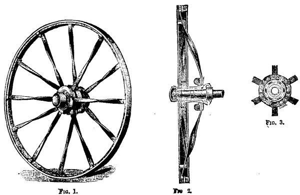
FIG. 1. FIG. 2. FIG. 3.
Fig. 1 is a perspective view of the wheel, Fig. 2 a transverse section, and Fig. 3 a longitudinal section of the boss. These wheels are made in two classes, A and B. Our engraving illustrates a wheel of the former class, these wheels being designed for use on rough and uneven roads, and when very great jolting strains may be met with, being stronger than those of class B design. The wheels are made with mild steel spokes, which are secured by metal straps in the recesses cut in the annular flanges on the boss, and by a taper bolt or rivet through the tire and rim. These spokes can be easily taken out and renewed when necessary by any unskilled person in a few minutes. The spokes being twisted midway of their length give greater strength to the wheel and power to resist side strains in pulling out of deep ruts or holes, without increasing the weight. The bosses and straps are made of malleable iron, in which the metal bushes are secured by means of a key with a washer screwed up on the front end. They are also fitted with steel oil caps to the end of the bushes, which are provided with a small set screw, so that the cap need not be taken off when it is necessary to lubricate the wheel, as by simply taking out the set screw oil may be poured through the hole into the cap. The set screw also forms a fulcrum for a key, so that the cap can be taken off or put on when required, as well as a means of preventing the cap being lost by shaking loose on rough roads. In all hot and dry climates, the continued shrinking of wood wheels and loosening of the tires is a constant source of expense and inconvenience. This wheel having a tire and rim entirely of metal does away with the difficulty, as the expansion and contraction are equal, consequently the tires need only be removed when worn out, and others can be supplied, drilled complete, ready for putting on, which can be done by any unskilled person. The wheels of class B design are the same in principle of construction as those of class A, but they have cast metal bosses or naves, without loose bushes, and are suitable for general work and ordinary roads where the strains are not so severe. The bosses or naves are readily removed in case of breakage, and they can be fitted with steel oil caps for lubricating.—Iron.
The apparatus shown in the accompanying engraving is designed for the manufacture of water gas for heating purposes, and is described in a communication, by Mr. W.A. Goodyear, to the American Institute of Mining Engineers.
The generator, A, is lined with refractory bricks and is filled with fuel, which may be coal, coke, or any suitable carbonaceous material. B and B' are two series of regenerating chambers lined with refractory brick, and, besides, filled with refractory bricks piled up as shown in the figure. The partitions, C and C', are likewise of refractory brick, and are rendered as air-proof as possible. Apertures, D and D', are formed alternately at the base of one partition and the top of the adjacent one, in order to oblige the gases that traverse the series of chambers to descend in one of them and to rise in the following, whatever be the number of chambers in use.
The two flues, E and E', lead from the bottom of the two nearest regenerator on each side to the bottom of the generator A, and serve to bring the current of air or steam into contact with the fuel. Valves, F and F', placed in these flues, permit of regulating the current in the two directions. Pipes, M and M', provided with valves, G and G', put the upper part of the generator in communication with the contiguous chambers, T and T'. Other pipes, N and N', with valves, H and H', permit of the introduction of a current of air from the outside into the chambers, T and T'. The pipes, O and O', and the valves, I and I', connected with a blower, serve for the same purpose. The pipes, P and P', and their valves, J and J', lead a current of steam. The conduits, Q and Q', and their valves, K and K', direct the gases toward the purifiers and the gasometer. Finally, the pipes, R and R', provided with valves, L and L', are connected with a chimney.
The generator, A, is provided at its upper part with a feed hopper. The doors, S and S', of the ash box close the apertures through which the ashes are removed.
When it is desired to use the apparatus, the pipes, P, Q, and R, are closed by means of their valves, J, K, and L, and the valve, I, of the pipe, O, is opened. The pipes, M and N, are likewise closed, while the flue, E, is opened. On the other side of the generator the reverse order is followed, that is to say, the flue, E', is closed, the pipes, M' and N', are opened, the pipes, O', P', and Q', are closed, and R' is opened.
A current of air is introduced through the pipe, O, and this traverses the regenerators, B, enters the chamber, T, and the generator, A, through the flue, E. As this air rises through the mass of incandescent fuel, its oxygen combines with an atom of carbon and forms carbonic oxide. This gas that is disengaged from the upper part of the fuel consists chiefly of nitrogen and carbonic oxide, mixed with volatile hydrocarburets derived from the fuel used. This gas, through the action of the air upon the fuel, is called "air gas," in order to distinguish it from the "water gas" formed in the second period of the process.
The air gas, on issuing from the generator through the pipe, M', in order to pass into the chamber, F', meets in the latter a second current of air coming in through the pipe, N', and which burns it and produces, in doing so, considerable heat. The strongly heated gases resulting from the combustion traverse the regenerators, B', and give up to the bricks therein the greater part of their heat, and finally make their exit, relatively cool, through the pipe, R', which leads them to the chimney. When the operation has been continued for a sufficient length of time to give the refractory bricks in the chamber, B', next the regenerator a high temperature, the valve, I, is closed, thus shutting off the entrance of air through the pipe, Q. The valve, F, of the flue, E, is also closed, and that of the pipe, M, is opened. The valves, G', H', L', of the pipes, M', N', R', are closed, and that, F', of the flue, E', is opened. The valve, J', of the pipe, P', is then opened, and a jet of steam is introduced through the latter.
The steam becomes superheated in traversing the regenerators, B', and in this state enters the bottom of the generator through the flue, E'. In passing into the incandescent fuel that fills the generator, the steam is decomposed, and there forms carbonic oxide, while hydrogen is liberated. The mixture of these two gases with the hydrocarburets furnished by the fuel constitutes water gas. This gas on making its exit from the generator through the pipe, M', passes through the chambers, B, and abandons therein the greater part of its heat, and enters the pipe, R, whence it passes through Q into the purifiers, and then into the gasometer.
As the production of water gas implies the absorption of a large quantity of sensible heat, it is accompanied with a rapid fall of temperature in the chambers, B', and eventually also in the generator, A, while at the same time the chambers, B, are but moderately heated by the sensible heat of the current of gas produced. When this cooling has continued so long that the temperature in the generator, A, is no longer high enough to allow the fuel to decompose the steam with ease, the valve, J', of the pipe, P', that leads the steam is closed, as is also the valve, K, of the pipe, Q, while the valves, L and H, of the pipes, R and N, are opened. After this the valve, I', is opened, and a current of air is let in through the pipe, O'. This air, upon traversing the chambers, B' and T', is raised to a high temperature through the heat remaining in these chambers, and then enters at the bottom of the generator, through the flue, E'. The air gas that now makes its exit from the pipe, M, in the chamber, T, meets another current of air coming from the pipe, N, and is thus burned. The products resulting from such combustion pass into the chambers, B, and then into the chimney, through the pipe, R. The temperature then rapidly lowers in the chambers, B', and rises no less rapidly in the generator, A, while the chambers, B, are soon heated to the same temperature that first existed in the chambers, B'. As soon as the desired temperature is obtained in the generator, A, and the chambers, B, the air is shut off by closing the valve, I', of the pipe, O'; the valve, F', of the flue, E', is also closed, the valves, G' and K', of the pipes, M' and Q', are opened, the valves, G, H, and L, of the pipes, M, N, and R, are closed, and the valve, F, of the flue, E, and the valve, J, of the pipe, P, are opened. A current of steam enters the apparatus through the pipe, P, traverses the chambers, B, and enters the generator through the flue, E. The gas produced makes its exit from the generator, passes through the pipe, M', and the chambers, T' and B', and the pipe, R, and enters the gasometer through the pipe, Q'.
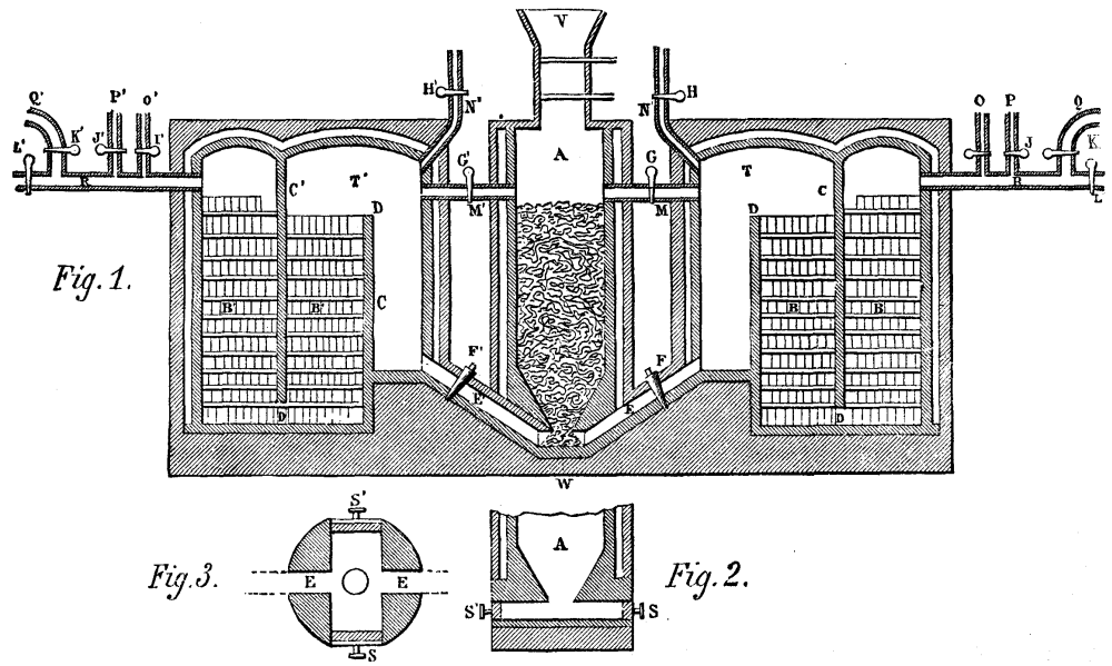
WATER-GAS APPARATUS.
When the chamber, B, and the generator, A, are again in so cool a state that the fuel no longer decomposes the steam easily, the valves are so maneuvered as to stop the entrance of the latter, and to send a current of air into the apparatus in the same direction that the steam had just been taking. The temperature thereupon quickly rises in the generator, A, while, at the same time, the combustion of the air gas produced soon reheats the chambers, B'. The cooled products of combustion go, as before, to the chimney. The position of the valves is then changed again so as to send a current of steam into the apparatus in a direction contrary to that which the air took in the last place, and the water gas obtained again is sent to the gasometer.
As will be seen, the process is entirely continuous, each current of air following the same direction in the apparatus (from left to right, or right to left) that the current of steam did which preceded it, while each current of steam follows a direction opposite that of the current of air which preceded it.
The inventor estimates that the cost of the coal necessary for his process will not exceed a tenth of a cent per cubic foot of gas.
One important advantage of the apparatus is that it can be made of any dimensions. Instead of giving the generator the limited size and form shown in the engraving, with doors at the bottom for the removal of the ashes by hand from time to time, it may be constructed after the general model of the shaft of blast furnaces, with a hearth at the base. Upon adding to the fuel a small quantity of flux, all the mineral parts thereof can be melted into a liquid slag, which may be carried off just like that of blast furnaces. There is no difficulty in constructing regenerators of refractory bricks of sufficient capacity, however large the generators be; and a single apparatus might, if need be, convert one thousand tons of anthracite per day into more than five million cubic feet of gas.
Ever since the introduction of electric lighting, the public have been assured, by those interested in the different kinds of lamps—arc, glow or otherwise—that henceforth, by means of such lamps, rooms are to be lighted without heat or baneful products such as they assert attend the use of gas, lamps, or candles. But I think it must not be implied, from what any one has said in favor of the electric light as a means of lighting our dwellings, that gas is unsuitable for the purpose, or that the glow lamp is a perfect substitute for gas, or that there is a very large difference throughout the year on the points of health, convenience, or comfort, or that the balance in favor rests with electric light upon all or any of these points. The fact is, the glow lamp is only one more means (not without certain disadvantages) of producing light added to those which already exist, and of which the public have the choice. Now, looking to best means of lighting rooms, and particularly the principal rooms of a small dwelling-house, I beg to say that the arguments which can be adduced in favor of gas lighting in preference to any other means greatly preponderate, and that it can be substantiated that, light for light, under the heads of convenience, health, comfort, reliability, readiness, and cheapness, gas is superior to all.
As a scientific means for the purposes mentioned, gas is comparatively untried. This assertion may sound somewhat astounding; but I think it is a true one. More than that, even in the crude and unscientific way in which it has most frequently been used up to the present, it has been far from unsuccessful in comparison with electricity or other means of lighting; and in the future it will prove the best and cheapest practical means, although, for effect, glow lamps may be used in palatial dwellings in conjunction with it.
It must be remembered that, in laying down a system of artificial lighting, we have to imitate, as well as we can, that most beautiful and perfect natural light which, without our aid, and without even a thought from us, shines regularly every day upon all, in such an immense volume, so perfectly diffused, and in such wonderful chemical combination, that it may safely be said that not one atom of the whole economy of Nature is unaffected by it, and that we and all the animal kingdom, in common with trees and plants, derive health and vigor therefrom. This glorious natural light leaves our best gas, electricity, oil lamp, and all our multiplicity of candles, immeasurably behind. But although we cannot hope to equal, in all its beneficent results, the effects of daylight, or to perfectly replace it, we can more perfectly make the lighting of our homes comfortable (and as little destructive to the eyes and to the general health) by the aid of gas than by any other means. It must also be borne in mind that, in this country at least, we have to fulfill the conditions of artificial lighting under frequent differences of temperature and barometric influence, exaggerated by the manner in which our homes are built; and that for at least nine months of the year we require heat as well as light in our dwellings, and that for the other three months (excepting in some few favored localities) the nights are often chilly, even though the days may be hot. Therefore, independently of any effect produced by the lighting arrangements, there must be widely different effects produced in the temperature and conditions of the air in rooms by influences entirely beyond our control.
As an example of what I mean, a short time ago I had to preside over a meeting which was held in a large room—one of two built exactly alike, and in communication with each other by means of folding doors. These rooms formed part of one of the best hotels in London—let us call it the "Magnificent." Of course, it was lighted by electric glow lamps, in accordance with the latest fashion in that department of artificial lighting, viz., suspension lamps, in which the glow lamps grew out of leaves and scrolls, twisted and twirled in and out, very much after the pattern of our most æsthetic gas lamps, which, of course, are in the style of the most artistic (late eighteenth century) oil lamps, which were in imitation of the most classic Roman lamps, which followed the Persian, and so on back to the time of Tubal Cain, the great arch-artificer in metals, who most likely copied in metal some lamps he had seen in shells or flints. Both rooms were heated by means of the good old blazing coal fire so dear to a Briton's heart; and they were ventilated with all due regard to the latest state of knowledge on the subject among architects and builders. In fact, no pains had been spared to make these rooms comfortable in the highest acceptation of the word.
There were, some of our members remarked, no gas burners to heat and deteriorate the atmosphere, or to blacken the ceilings; and therefore, under the brilliant sparkle of glow lamps, the summit of such human felicity as is expected by a body of eighteen or twenty business men, intent on dispatching business and restoring the lost tissue by means of a nice little dinner afterward, ought, according to the calculations of the architect of the building, to have been reached. I instance this case because it is a typical one, which, under most aspects, does not materially differ from the conditions of home life in such residences as those whose occupiers are likely to use electric lighting. The rooms were spacious (about 20 feet by 35 feet, and about 15 feet high); and they were lighted during the day by means of large lantern ceiling-lights, with double glass windows. The evening in question was chilly, not to say cold.
Upon commencing our business, we all admired the comfort of the room; but as time went on, most of the company began to complain of a little draught on the head and back of the neck. The draught, which at first was only a suspicion, became a certainty, and in another hour or so, by the time our business was over, notwithstanding a screen placed before the door, and a blazing fire, we were delighted to make a change to the comfortable dining-room, which communicated with the room we had just left by means of folding doors, closed with the exception of just sufficient space left at one end of the room to allow a waiter to pass in and out. Very curiously, before the soup was finished, we became aware that the candles which assisted the electric glow lamps (merely for artistic effect) began to flare in a most uncandlelike manner—the flames turning down, as if some one were blowing downward on the wicks; and at the same time the complaints of "Draughts, horrid draughts!" became general, and from every quarter. Finding that, as the dinner went on, the discomfort became unbearable, even although the doors were shut and screens put before them, I gave up dining, and took to scientific discovery. The result of a few moments' observation induced me to order "those gas jets," which I saw peeping out from among the foliage of the electroliers, to be lighted up. In two or three minutes the flames of the candles burned upright and steadily, and in less than ten minutes the draughts were no longer felt; in fact, the room became really comfortable.
The reason of the change was simple. The stratum of air lying up at the ceiling was comparatively cold. The column of heated air from the bodies of the twenty guests, joined to the heat produced by the movements of themselves and the waiters, together with the steam from the viands and respiration, displaced the colder air at the ceiling, and notably that coldest air lying against the surface of the glass. This cold air simply dropped straight down, after the manner of a douche, on candles and heads below. The remedy I advised was the setting up of a current of hotter steam and air from the gas burners, which stopped the cooling effect of the glass, and created a stratum of heated steam and air in slow movement all over the ceiling. The effect was a comfortable sensation of warmth and entire absence of draught all round the table. Later on, to avoid the possibility of overheating the room, the gas was put out, and the electric lights left to themselves. But before we left, the chilliness and draughts began to be again felt.
The incident here narrated occurred at the end of the month of April last, when we might reasonably have hoped to have tolerably warm nights. It is therefore clear that in this instance neither electricity nor candles could effectually replace gas for lighting purposes. They both did the lighting, but they utterly failed to keep the currents of air steady. I have always remarked draughts whenever I have remained any length of time in rooms where the electric light is used. On a warm evening the electric light and candles would undoubtedly have kept the room cooler than gas, with the same kind of ventilation; I do not think they would have put an end to cold draughts. This the steam from the gas does in all fairly built rooms.
It is a well-known fact that dry air parts with its relatively small amount of specific heat, in an almost incredibly rapid manner, to anything against which it impinges. Steam, on the contrary, from its great specific heat, remains in a heated state for a much longer time than air. It is not so suddenly reduced to a low temperature, and in parting with its own heat it communicates a considerable amount of warmth to those bodies with which it comes in contact. Thus the products of the combustion of gas (which are principally steam) serve a useful purpose in lighting, by keeping at the ceiling level a certain stratum of heated vapor, which holds up, as it were, the carbonic acid and exhalation from the lungs given off by those using the room. The obvious inference, therefore, is that if we take off these products from the level of the ceiling, we shall take off at the same time the impure and vitiated air. On the other hand, if we make use of a system of artificial lighting, which does not produce any steam, then we shall have to adopt means to keep the air at the ceiling level warm, in order to prevent the heated impure air from descending in comparatively rapid currents, after having parted with its heat to the ceiling. It may very frequently be observed on chilly days that a number of currents of cold air seem to travel about our rooms, although there may be no crevices in the doors and windows sufficient to account for them; and, further, that these currents of cold air are not noticed when the curtains are drawn and the gas is lighted. The reason is that there is generally not enough heat at the ceiling level in a room unlighted with gas to keep these currents steady. Hence the complaints of chilliness which we constantly hear when electric lights are used for the illumination of public buildings. For example, at the annual dinner of the Institution of Civil Engineers, held at the end of April last in the Conservatory of the Horticultural Gardens, the heat from the five hundred guests, and from an almost equal number of waiters and attendants, displaced the cold air from the dome of the roof, and literally poured down on the assembly (who were in evening dress) in a manner to compel many of them to put on overcoats. If the Conservatory had been lighted with gas suspended below the roof, this would not have been the case, because sufficient steam would have been generated to stop these cold douches, and keep them up in the roof. In fact, if electric lights are to be used in such a building, it will be necessary to lay hot-water pipes in the roof, to keep warm the upper as well as the lower stratum of air, and thus steady the currents.
Having pointed out difficulties which arise under certain conditions of the atmosphere in rooms built with care, to make them comfortable when electric lighting is substituted for gas, I will lay before you some few particulars relative to the condition of small rooms of about 12 ft. by 15 ft. by 10 ft., or any ordinary room such as may be found in the usual run of houses in this country. The cubical contents of such a room equals 1,700 cubic feet. If the room is heated by means of a coal fire, we shall for the greatest part of the year have a quantity of air taken out of it at about 2 feet from the floor by the chimney draught, varying (according to atmospheric conditions and the state of the fire) from 600 to 2,000 or more cubic feet. This quantity of air must, therefore, be admitted by some means or other into the room, or the chimney will, in ordinary parlance, "smoke;" that is, the products of combustion, very largely diluted with fresh air, will not all find their way up the flue with sufficient velocity to overcome the pressure of the heavy cold air at the top of the chimney. If no proper inlets for air are made, this supply to the fire must be kept up from the crevices of the doors and windows. In the line of these currents of cold air, or "draughts" as they are usually called, it is impossible to experience any comfort—quite the contrary; and colds, rheumatism, and many other serious maladies are brought on through this abundant supply of fresh air in the wrong way and place.
According to General Morin (one of the best authorities on ventilation), 300 cubic feet of air per hour are required for every adult person in ordinary living rooms. Peclet says 250 cubic feet are sufficient; less than this renders the atmosphere stuffy and unhealthy. It is generally admitted that an average adult breathes out from 20 to 30 cubic inches of steam and vitiated air per minute, or, as Dr. Arnott says, a quantity equal in bulk to that of a full-sized orange. This vitiated air and steam is respired at a temperature of 90° Fahr.; and therefore, by reason of this heat, it immediately ascends to the ceiling, together with the heat and carbonic acid given off from the pores of the skin. This fact, by the bye, can be clearly demonstrated by placing a person in the direct rays from a powerful limelight or electric lamp, and thus projecting his shadow sharply on a smooth white surface. It will be observed that from every hair of the head and beard, and every fiber of his clothing, a current of heated air in rapid movement is passing upward toward the ceiling. These currents appear as white lines on the surface of the wall; the cause probably being that the extreme rarefaction of the air by the heat of the body enables the rays of light to pass through them with less refraction than through the denser and more moist surrounding cold air. An adult makes, on an average, about 15 respirations per minute, and therefore he in every hour renders to the atmosphere of the room in which he is staying from 10 to 15 cubic feet of poisonous air. This rises to the ceiling line, if it is not prevented; and thus vitiates from 100 to 150 cubic feet of air to the extent of 1 per cent, in an hour. General Morin thought that air was not good which contained more than ½ per cent, of air which had been exhaled from the lungs; and when we consider how dangerous to health these exhalations are, we must admit that he was right in his view. Therefore in one hour the 15 foot by 12 foot room is vitiated to more than 2 feet from the ceiling by one person to the extent of ½ per cent., and it will be vitiated by two persons to the extent of 1 per cent, in the same time.
It must be remembered here that the degree of diffusion of the vitiated air into the lower fresh air contained in the remaining 8 feet of the height of the room depends very materially on the difference of temperature between these upper and lower strata and the movements of air in the room. The heavy poisonous vapors and gases fall into and diffuse themselves among the fresh air of the lower strata—very readily if they are nearly the same temperature as the upper, but scarcely at all if the air at the ceiling line is much hotter. Hence it occurs that, in warmed rooms of such size as I have mentioned, where one or two petroleum lamps are used for lighting them, after two or three hours of occupation by a family of three or four persons in winter weather, the air at the ceiling line has become so poisonous that a bird dies if allowed to breathe it for a very short time—sometimes, indeed, for only a few minutes. With candles, if the illumination of the room is maintained at the same degree as in the case of lamps, the contamination of the air is very much worse. It is doubtless the case that poisonous germs are rapidly developed in atmospheres which are called "stuffy;" and although, in a healthy state of the body, we are able to breathe them without perceptible harm, yet even then the slight headache and uneasiness we feel is a symptom which does not suffer itself to be lightly regarded, whenever, from some cause or other, the general condition is weak.
The products of combustion from coal gas (which are steam and carbonic acid mixed with an infinitesimal quantity of sulphur) are, proportionately, far less injurious to animal life than the products from an equal illuminating power derived from either oil or candles. They are, however, it is certain, destructive to germ life; and therefore, if taken off from the ceiling level, where they always collect if allowed to do so, no possible inconvenience or danger to health can be felt by any one in the room. But in our endeavors to take off the foul air at the ceiling, we encounter our first serious check in all schemes of ventilation. We draw the elevation and section of the room, and put in our flues with pretty little black arrows flying out of the outlets for vitiated air, and other pretty little red arrows flying in at the inlets; but when we see our scheme in practice, the black arrows will persist in putting their wings where their points ought to be; in other words, flying into instead of out of the room.
One of the best ways of finding the true course of all the hot and cold currents in a room is to make use of a small balloon, such as used to be employed for ascertaining the specific gravity of gases; and, having filled it with ordinary coal gas, balance it by weights tied on to the car till it will rest without going up or down in a part of the room where the air can be felt to be at about the mean temperature, and free from draught. Then leave it to itself, to go where it will.
As soon as it arrives in a current of heated air, it will ascend, passing along with the current, and descending or rising as the current is either warm or cold. The effect of the cold fresh air from windows or doors, as well as the effect of the radiant heat from the fire, can be thus thoroughly studied. Some of our pet theories may receive a cruel shock from this experiment; but, in the end, the ventilation of the room will doubtless be benefited, if we apply the information obtained. It will be discovered that the wide-throated chimney is the cause of the little black arrows turning their backs on the right path and our theoretical outlets for vitiated air becoming inlets. The chimney flue must have an enormous supply of air, and it simply draws it from the most easily accessible places. From 1,000 to 2,000 cubic feet of air per hour is a large "order" for a small room. Therefore, until we have made ample provision for the air supply to the fire, it is quite useless to attempt to ventilate the upper part of the room, either by ventilating gas lights or one of the cheap ventilators with little talc flappers, opening into the chimney when there is an up draught, and shutting themselves up when there is any tendency to down draught. The success of these and all other ventilators depends upon there being a good supply of air from under the door or through the spaces round the window frames. These fresh air supplies are, of course, unendurable; but if one of the spaces between the joists of the floor is utilized to serve as an air conduit, and made to discharge itself under the fender (raised about two inches for the purpose), quite another state of things will be set up. Then the supply of air thus arranged for will satisfy the fire, without drawing from the doors and windows, and at the same time supply a small quantity of fresh air into the room. But the important fact that the radiant heat from the fire will pass through the cold air without warming it all must not be lost sight of. In reality, radiant heat only warms the furniture and walls of the room or whatever intercepts its rays. The air of the room is warmed by passing over these more or less heated surfaces; and as it is warmed, it rises away to the ceiling. Therefore, if we desire to warm any of this fresh air supplied to the fire, it must be made to pass over a heated surface. The fender may be used for this purpose by filling up the two inch space along the front, as shown in the drawing, with coarse perforated metal. This will also prevent cinders from getting under it. It will be found that for the greater part of the year the chimney ventilator and the supply to the fire will materially prevent "stuffiness," and keep those disagreeable draughts under control, even although the room be lighted with a 3 light chandelier burning a large quantity of gas.
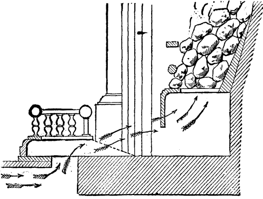
With improvements in gas burners, we may expect to light rooms perfectly with a less expenditure of gas than we now do. But we cannot light a room without in some measure creating heat; and I think I have shown that we want this heat at the ceiling line for the greater part of the year.
In summer we do not use gas for many hours; but, on the other hand, it is more difficult, with an outside temperature at 65° to 70° Fahr., to keep the air in proper movement in small rooms. There are also times in the fall of the year, and also in spring, when the nights are unusually warm; and, with a few friends in our rooms, the lighting becomes a "hot" question, not to say a "burning" one. On these occasions we have to resort to exceptional ventilation, which for ordinary every-day life would be too much. It is then, and on summer nights, that the system of ventilation by diffusion is most useful. To explain it, when two volumes of air of different temperatures or specific gravities find themselves on opposite sides of a screen or other medium, of muslin, cloth, or some more or less porous substance, they diffuse themselves through this medium with varying rapidity, until they become of equal density or temperature. Therefore, if we fill the upper part of a window (which can be opened, downward) with a strained piece of fine muslin or washed common calico, the air in the room, if hotter than the external air, will, when the window is more or less opened, pass out readily into the cooler air, and the cooler air will pass in through the pores of the medium. The hotter air passing out faster than the cooler air will come in, no draught will be experienced; and the window may be opened very widely without any discomfort from it.
It is, of course, quite impossible, in the limits of a paper, to do more than indicate a means of ventilation which will be effective under most circumstances of lighting with those gas burners and fittings usually employed, and which will lend itself readily to modifications which will be necessitated by the use of some of the newest forms of burners and ventilating gas lights.
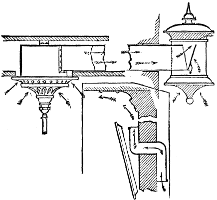
In conclusion, I wish to draw attention to an important discovery I have made in reference to blackened ceilings, for which, up to the present time, gas has been chiefly blamed. I have long entertained the belief that with a proper burner it is possible to obtain perfect combustion, without any smoke; and a series of experiments with white porcelain plates hung over some burners used in my own house proved conclusively that the discoloration which spread itself all over my whitewashed ceilings arose from the state of the atmosphere, which in all large towns is largely mixed with heavy smoky particles, and from the dust or dirt created in rooms by the use of coal fires as well as from the smoke which, more frequently than one is at first supposed to imagine, escapes from the fire-place into the room. I therefore, in two of my best rooms, which required to have the ceilings whitened every year, substituted varnished paper ceilings (light oak paper, simply put on in the usual way, and varnished) instead of whitewash. I also changed the coal fires for gas fires. These alterations have gone through the test of two winters, and the ceilings are now as clean as when they were first done. The burners have been used every night, and the gas fires every day, during the two winters. No alteration has been made in the burners employed, and no "consumers" have been used over them. If the varnished paper ceilings are tried, I am sure that every one will like them better than the time honored dirty whitewash, which is simply a fine sieve. This fact is clearly shown by the appearance of the rafters, which, after a short time, invariably show themselves whiter than the spaces between.
Mr. G.L. Anders' telephone, shown in the accompanying cut, combines in a single apparatus a transmitter, A, a receiver, B, and a pile, C. The transmitter consists of a felt disk, a, containing several large apertures, and fixed by an insulating ring, c, to a metallic disk, d, situated within the box, D. The apertures, b, are filled with powdered carbon, e, and are covered by a thin metal plate, f, which is fixed to the insulating ring, c, by means of a metallic washer, g. Back of the transmitter is arranged the receiver, B, which consists of an ordinary electro-magnet with a disk in front of its poles. The pile, C, placed behind the receiver, consists of a piece of carbon, h, held by a partition, i, and covered with a salt of mercury, and of a plate of zinc, l, which is held at a distance from the mercurial salt by a spring, m, fixed to the insulating piece, n.
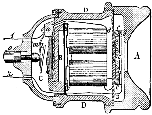
ANDERS TELEPHONE
When the button, o, which is a poor conductor, is pressed, the zinc plate, l, comes into contact with the mercurial salt, and the circuit is closed through the line wire 1, the pile, the receiver, the transmitter, and the line wire 2, while when the button is freed the current no longer passes. The apparatus, then, can serve as a receiver or transmitter only when the button is pressed.—Bull. de la Musee de l'Industrie.
When the sea is rough, and the screw leaves the water as a consequence of the ship's motions, the rotary velocity of the screw and engine increases to a dangerous degree, because the resistance that the screw was meeting in the water suddenly disappears. When the screw enters the water again, the resistance makes itself abruptly felt, and causes powerful shocks, which put both the screw and engine in danger. Ordinary regulators are powerless to overcome this trouble, since their construction is such that they act upon the engine only when the excess of velocity has already been reached.
Several remedies have been proposed for this danger. For example, use has been made of a float placed in a channel at the side of the screw, and which closes the moderator valve by mechanical means or by electricity when the screw descends too low or rises too high.
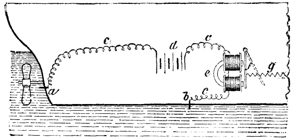
BROWN'S ELECTRIC SPEED REGULATOR.
Mr. Brown's system is based upon a new idea. The apparatus (see figure) consists of two contacts connected by an electric circuit. One of them, b, is fixed to the ship in such a way as to be constantly in the water, while the other, a, corresponds to the position above which the screw cannot rise without taking on a dangerous velocity. In the normal situation of the ship, the electric circuit, c (in which circulates a current produced by a dynamo, d), is closed through the intermedium of the water, which establishes a connection between the two contacts. When the contact, a, rises out of the water, the current is interrupted. The electro, d, then frees its armature, f, and the latter is pulled back by a spring—a motion that sets in action a small steam engine that closes the moderator valve. When the contact, a, is again immersed, the electro, e, attracts its armature, and thus brings the moderator valve back to its normal position. It is clear that the contact, a, must be insulated from the ship's side.
Several contacts, a, might be advantageously arranged one above another, in order to close the moderator valve more or less, according to the extent of the screw's rise or fall.
We illustrate to-day a new application of electricity to railroad crossing signaling which the Pennsylvania Steel Company, of Steelton, Pa., has just perfected. By its operation an isolated highway crossing in the woods or any lonely place can be made perfectly safe, and that, too, without the expense of gates and a man to work them or of a flagman. It is surely a great improvement over the old methods, and it is likely to have a large sale. In addition to considerations of safety, possible saving in salaries to railroad companies by its use will be great. This device is more reliable than a human being, and can make any crossing safe to which it is applied. Its operation is described as follows:
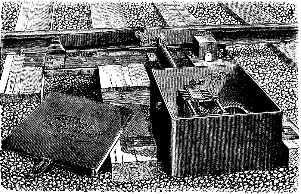
FIG. 2.—MAGNETO-ELECTRIC CROSSING SIGNAL
The illustration shows the device as used on a single track railroad, where it is so arranged as to be operated only by trains approaching the crossing (i.e., in the form illustrated, from the right). A similar box on the other side of the crossing is used for trains approaching in the other direction. Two plates connected by a link, and pivoted, are placed alongside of one rail, close enough to it to be depressed by the treads of the wheels. By another link, one of the plates called the rock plate (the one to the right) is connected to a rock shaft which extends through a strong bearing into the heavy iron case or box shown, at a suitable distance from the rail, within which an electric generator is placed; the whole being mounted and secured upon the ends of two long ties framed to receive it.
The action of this rock plate is peculiar. It is pivoted at the rear end, not to a fixed point, but to a short crank arm, the bearing for which is inclosed in the small box shown. As the first wheel of a train which is approaching in the desired direction (from the right in the engraving) touches it, it will be seen that it must not only depress it, but produce a slight forward motion, causing a corresponding rotary motion in the rock shaft which actuates the apparatus. On the other hand, when a train is approaching from the other direction, or has already passed the crossing, its wheels strike first the curved plate to the left of the illustration, and by means of the peculiar link connections shown, depress the rock plate so as to clear the wheels before the wheels touch it, but the depression is directly vertical, so that it does not give any horizontal motion to it, which would have the effect of actuating the rock shaft. Consequently, trains pass over the apparatus in one direction without having any effect upon it whatever, the different point at which the same force is applied to the rock plate giving the latter an entirely different motion.
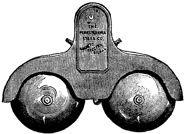
FIG. 2.—MAGNETO-ELECTRIC CROSSING SIGNAL
The slight rotary motion which is in this way communicated to the rock shaft, when a train is approaching in the right direction, compresses a spring inside the case. As each wheel passes off the rock plate, the reaction of the spring throws it up again to its former position, giving additional speed to the gearing within, which is set in motion at the passage of the first wheel, and operates the electric "generator." The spring is really the motive power of the alarm. A small but heavy fly-wheel is connected with the apparatus, the top of which is just visible in the engraving, which serves to store up power to run the "generator," which is nothing more than a small dynamo, for the necessary number of seconds after the rear of the train has passed. The dynamo dispenses with all need for batteries, and reduces the work of maintenance to occasionally refilling the oil-cups and noticing if any part has been broken.
A suitable wire circuit is provided, commencing at the generator with insulated and protected wire, and continued with ordinary telegraph wire, which can be strung on telegraph poles or trees leading to the electric gong, Fig. 2, which rings as long as the armature revolves. It is a simple matter so to proportion the mechanism for the required distance and speed that the revolutions of the armature and the ringing of the gong shall continue until the train reaches the crossing; and as each wheel acts upon the apparatus, the more wheels there are in the train the longer the bell will ring, a very convenient property, since the slowest trains have nearly always the most wheels. The practical limits to the ringing of the gong are that it will stop sounding after the head of the train has passed the crossing and before or very soon after the rear has passed. A "wild" engine running very slowly might not actuate the signal as long as was desirable, but even then it is not unreasonably claimed the warning would probably last long enough for all practical requirements, as a team approaching a crossing at eight miles per hour takes 42 seconds to go 500 feet. All the bearings of any importance are self-lubricated by oil cups, the whole apparatus being designed to require inspection not more than once a month. The iron case when shut is water-tight, and when duly locked cannot be maliciously tampered with without breaking open the case; so that, the manufacturers claim, it will not be essential to examine it more than once a month. The parts outside the case are all strong and heavy, and not likely to get out of order, while easily inspected.
The apparatus can be used for announcing trains as well as sounding alarms, as the gongs can be placed upon any post or building. The gong has a heavy striker, and makes a great deal of noise, so that no one should fail to hear it.—Railway Review.
Professor Theodore G. Wormley, in the new edition of his work, gives the following sizes of blood corpuscles, as measured by himself and Professor Gulliver. We have only copied the sizes for mammals and birds. It will be seen that, with three or four exceptions, the sizes obtained by the two observers are practically the same:
    Mammals              Wormley.      Gulliver.


   Man                    1-3250        1-3260
   Monkey                 1-3382        1-3412
   Opossum                1-3145        1-3557
   Guinea pig             1-3223        1-3538
   Kangaroo               1-3410        1-3440
   Muskrat                1-3282        1-3550
   Dog                    1-3561        1-3532
   Rabbit                 1-3653        1-3607
   Rat                    1-3652        1-3754
   Mouse                  1-3743        1-3814
   Pig                    1-4268        1-4230
   Ox                     1-4219        1-4267
   Horse                  1-4243        1-4600
   Cat                    1-4372        1-4404
   Elk                    1-4384        1-3938
   Buffalo                1-4351        1-4586
   Wolf (prairie)         1-3422        1-3600
   Bear (black)           1-3656        1-3693
   Hyena                  1-3644        1-3735
   Squirrel (red)         1-4140        1-4000
   Raccoon                1-4084        1-3950
   Elephant               1-2738        1-2745
   Leopard                1-4390        1-4319
   Hippopotamus           1-3560        1-3429
   Rhinoceros             1-3649        1-3765
   Tapir                  1-4175        1-4000
   Lion                   1-4143        1-4322
   Ocelot                 1-3885        1-4220
   Mule                   1-3760
   Ass                    1-3620        1-4000
   Ground squirrel        1-4200
   Bat                    1-3966        1-4173
   Sheep                  1-4912        1-5300
   Ibex                   1-6445
   Goat                   1-6189        1-6366
   Sloth                                1-2865
   Platypus (duck-billed)               1-3000
   Whale                                1-3099
   Capybara               1-3164        1-3190
   Seal                                 1-3281
   Woodchuck                            1-3484
   Muskdeer                             1-12325
   Beaver                               1-3325
   Porcupine                            1-3369
   Llama,  Long diam.     1-3201        1-3361
           Short "        1-6408        1-6229
   Camel,  Long diam.     1-3331        1-3123
           Short "        1-5280        1-5876


                          WORMLEY               GULLIVER.
      Birds.           Length. Breadth.     Length. Breadth.


  Chicken              1-2080   1-3483      1-2102   1-3466
  Turkey               1-1894   1-3444      1-2045   1-3599
  Duck                 1-1955   1-3504      1-1937   1-3424
  Pigeon               1-1892   1-3804      1-1973   1-3643
  Goose                                       1836   1-3839
  Quail                                       2347   1-3470
  Dove                                        2005   1-3369
  Sparrow                                     2140   1-3500
  Owl                                         1736   1-4076
The subject of minute measurements was discussed in an interesting manner in an address before the Microscopical Section of the A.A.A.S. last year, an abstract of which was published in this journal, vol. v., p. 181.
The slight differences in size accurately given in this table are not always appreciable under modern amplification, but under a power of 1,150 diameters "corpuscles differing by the 1-100000 of an inch are readily discriminated." For the conclusions of Prof. Wormley as regards the possibility of identifying blood of different animals, the reader is referred to his book on Micro-Chemistry of Poisons.—Amer. Micro. Jour.
E. Joerss has investigated the question whether ointments made with vaseline or other petroleum ointments are really as difficult of resorption by the skin, or of yielding their medicinal ingredients to the latter, as has been asserted. In solving this question, he considered himself justified in drawing conclusions from the manner in which such compounds behaved toward dead animal membrane. If any kind of osmosis could take place, he argued, from ointments prepared with vaseline, etc., through dead membranes, such osmosis would most probably also take place through living membranes. At all events, the endosmotic or exosmotic action of the skin of a living body must necessarily play an important role in the absorption of medicinal agents; and, on the other hand, it is plain that fats, which render the living skin impermeable, necessarily also diminish or entirely neutralize its osmotic action. To test this, the author made the following experiments:
Bladder was tied over the necks of three wide-mouthed vials, with bottoms cut off, and each was filled with iodide of potassium ointment.
No. 1 contained an ointment made with lard.
No. 2, one made with unguentum paraffini (Germ. Pharm.), and
No. 3, one made with unguentum paraffini mixed with 3 per cent. of lard.
All three vials were then suspended in beakers filled with water. After standing twenty-four hours at the ordinary temperature, the contents of none of the beakers gave any iodine reaction. After having been placed into a warm temperature, between 25-37° C., all three showed iodine reactions after three hours, Nos. 2 and 3 very strongly, No. 1 (with lard alone) very faintly.
The same experiment was now repeated, with the precaution that the bladder was previously washed completely free from chlorine. Each vial was suspended, at a temperature of 25-27° C., in 50 grammes of distilled water. After three hours, the contents of No. 1 (containing the ointment made with lard) gave no iodine reaction; the contents of the other two, however, gave traces. After eight hours no further change had taken place. The temperature was now raised to 30-35° C., and kept so for eight hours. All three beakers now gave a strong iodine reaction, 0.2 c.c. of normal silver solution being required for each 15 grammes of the contents of the beakers.
In addition to the iodide, some of the fatty base had osmosed through the membrane in each case.
The next experiment was made by substituting a piece of the skin (freed from chlorine by washing) of a freshly killed sheep for the bladder. The ointment in No. 3 in this case was made with 10 per cent. of lard. No reaction was obtained, at the ordinary temperature, after twelve hours, nor after eight more hours, at a temperature of 25-30° C. After letting them stand for eight hours longer at 30-37° C., a faint reaction was obtained in the case of the ointment made with unguentum paraffini; a still fainter with No. 3; but no reaction at all with No. 1 (that made with lard). None of the fats passed through by osmosis. After eight hours more, the iodine reaction was quite decisive in all cases, but no fat had passed through even now. On titrating 20 grammes of the contents of each beaker,
        No. 1 required 0.5 c.c. of silver solution.
        No. 3    "     0.5 c.c.         "
        No. 2    "     0.7 c.c.         "
showing that the most iodine had osmosed in the case of the ointment made with unguentum paraffini (equivalent to vaseline).
I.—If we throw a stone into the water, a wave will be produced that will extend in a circle. The size of this wave and the velocity with which it extends depend upon the size of the stone, that is to say, upon the intensity of the mechanical action that created it. The extent and depth of the water are likewise factors.
If we cause a cord to vibrate in the water, we shall obtain a succession of waves, the velocity and size of which will be derived from the cord's size and the intensity of its action. These waves, which are visible upon the surface, constitute what I shall call mechanical waves. But there will be created at the same time other waves, whose velocity of propagation will be much greater than that of the mechanical ones, and apparently independent of mechanical intensity. These are acoustic waves. Finally, there will doubtless be created optical waves, whose velocity will exceed that of the acoustic ones. That is to say, if a person fell into water from a great height, and all his senses were sufficiently acute, he would first perceive a luminous sensation when the first optical wave reached him, then he would perceive the sound produced, and later still he would feel, through a slight tremor, the mechanical wave.6
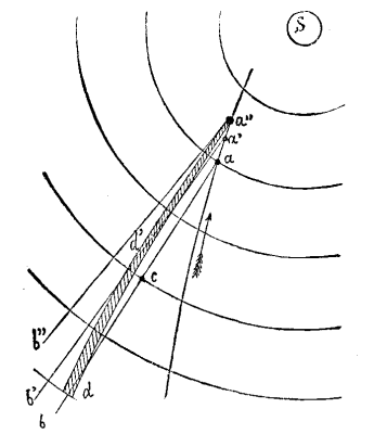
I
Under the action of the same mechanical energy there form, then, in a mass of fluid, waves that vary in nature, intensity, and velocity of propagation; and although but three modes appreciable to our senses have been cited, it does not follow that these are the only ones possible.
We may remark, again, that if we produce a single wave upon water, it will be propagated in a uniform motion, and will form in front of it successive waves whose velocity of propagation is accelerated.
This may explain why sounds perceived at great distances are briefer than at small ones. A detonation that gives a quick dead sound at a few yards is of much longer duration, and softer at a great distance.
The laws that govern the system of wave propagation are, then, very complex.
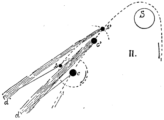
II
II.—If an obstacle be in the way of the waves, there will occur in each of them an alteration, a break, which it will carry along with it to a greater or less distance. This succession of alterations forms a trace behind the obstacle, and in opposition to the line of the centers. Finally, if the obstacle itself emits waves in space that are of less intensity then those which meet it, these little waves will extend in the wake of the large ones, and will form a trace of parabolic form situated upon the line of the centers.
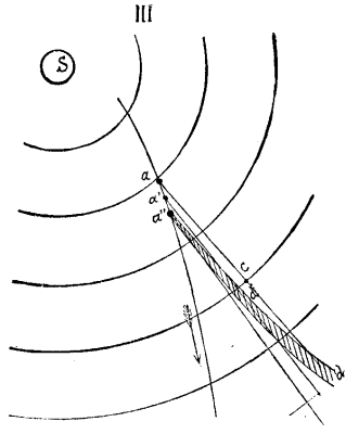
III
III.—Let us admit, then, that the sun, through the peculiar energy that develops upon its surface or in its atmosphere, engenders in ethereal space successive waves of varying nature and intensity, as has been said above, and let us admit that its mechanical waves are traversed obliquely (Fig. 1) by any spherical body—by a comet, for example; then, under the excitation of the waves that it is traversing, and through its velocity, the comet will itself enter into action, and produce mechanical waves in its turn. As the trace produced in the solar waves consists of an agitation of the ether on such trace, it will become apparent, if we admit that every luminous effect is produced by an excitation—a setting of the ether in vibration. The mechanical waves engender of themselves, then, an emission of optical waves that render perceptible the alteration which they create in each other.
Let a be the position of the comet. The altered wave, a, will carry along the mark of such alteration in the direction a b, while at the same time extending transversely the waves emitted by the comet. During this time the comet will advance to a', and the wave will be altered in its turn, and carry such alteration in the direction, a' b'.
The succession of all these alterations will be found, then, upon a curve a'' d' d, whose first elements, on coming from the comet, will be upon the resultant of the comet's velocity, and of the propagation of the solar waves. Consequently, the slower the motion of the comet, with respect to the velocity of the solar waves, the closer will such resultant approach the line of centers, and the more rectilinear will appear the trace or tail of the comet.
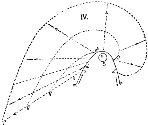
IV
IV.—If the comet have satellites, we shall see, according to the relative position of these, several tails appear, and these will seem to form at different epochs. If c and s be the positions of a comet and a satellite, it will be seen that if, while the comet is proceeding to c', the satellite, through its revolution around it, goes to s', the traces formed at c and s will be extended to d and d', and that we shall have two tails, c' d and s' d', which will be separated at d and d' and seem to be confounded toward c' s'.
V.—When the comet recedes from the sun, the same effect will occur—the tail will precede it, and will be so much the more in a line with the sun in proportion as the velocity of the solar waves exceeds that of the comet.
If we draw a complete diagram (Fig. 4), and admit that the alteration of the solar waves persists indefinitely, we shall see (supposing the phenomenon to begin at a) that when the comet is at a 1, the tail will and be at a 1 b; when it is a 2 the tail will be at a 2 b'; and when it is at a 4, the tail will have become an immense spiral, a 4 b'''. As in reality the trace is extinguished in space, we never see but the origin of it, which is the part of it that is constantly new—that is to say, the part represented in the spirals of Fig. 4.
The comet of 1843 crossed the perihelion with a velocity of 50 leagues per second; it would have only required the velocity of the solar waves' propagation to have been 500 leagues per second to have put the tail in a sensibly direct opposition with the sun.
Knowing the angle γ (Fig. 5) that the tangent to the orbit makes with the sun at a given point, and the angle δ of the track upon such tangent, as well as the velocity v of the comet, we can deduce therefrom the velocity V of the solar waves by the simple expression:
  V = v × (sinus δ / sinus(γ - δ)) or (Fig. 1),


  V = da/t'',
t'' being the time taken to pass over aa''.
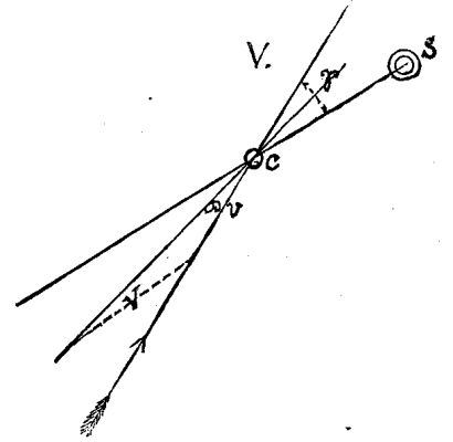
V
VI.—The tail, then, is not a special matter which is transported in space with the comet, but a disturbance in the solar waves, just as sound is an atmospheric disturbance which is propagated with the velocity of the sonorous wave, although the air is not transported. The tail which we see in one position, then, is not that which we see in another; it is constantly renewed. Consequently, it is easy to conceive how, in as brief a time as it took the comet of 1843 to make a half revolution round the sun, the tail which extended to so great a distance appeared to sweep the 180° of space, while at the same time remaining in opposition to the great luminary.
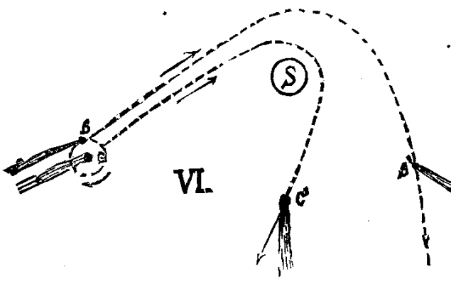
VI
The spiral under consideration may be represented practically. If to a vertical pipe we adapt a horizontal one that revolves with a certain velocity, and throws out water horizontally, it will be understood that, from a bird's eye view, the jet will form a spiral. Each drop of water will recede radially in space, the spiral will keep forming at the jet, and if, through any reason, the latter alone be visible, we shall see a nearly rectilinear jet that will seem to revolve with the pipe.
Finally, if the jet be made to describe a curve, m n (Fig. 4), while it is kept directed toward the opposite of a point, c, the projected water will mark the spiral indicated, and this will continue to widen, and each drop will recede in the direction shown by the arrows.
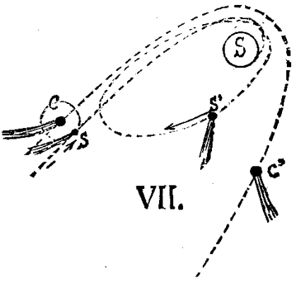
VII
VII.—It seems to result from this explanation that all the planets and their satellites ought to produce identical effects, and have the appearance of comets. In order to change the conditions, it suffices to admit that the ethereal mass revolves in space around the sun with a velocity which is in each place that of the planets there; and this is very reasonable if, admitting the nebular hypothesis, we draw the deduction that the cause that has communicated the velocity to the successive rings has communicated it to the ethereal mass.
The planets, then, have no appreciable, relative velocity in space, and for this reason do not produce mechanical waves; and, if they become capable of doing so through a peculiar energy developed at their surface, as in the case of the sun, they are still too weak to give very perceptible effects. The satellites, likewise, have relatively too feeble velocities.
The comet, on the contrary, directly penetrates the solar waves, and sometimes has a relatively great velocity in space. If its proper velocity be of directly opposite direction to that of the ethereal mass's rotation, it will then be capable of producing sufficiently intense mechanical effects to affect our vision.
VIII.—Finally, seeing the slight distances at which these stars pass the sun, the attraction upon the comet and its satellites may be very different, and the velocity of rotation of the latter, being added to or deducted from that of the forward motion, there may occur (as in the case shown in Fig. 6) a separation of a satellite from the principal star. The comet then appears to separate into two, and each part follows different routes in space; or, as in Fig. 7, one of the satellites may either fall into the sun or pursue an elliptical orbit and become periodical, while the principal star may preserve a parabolic orbit, and make but one appearance.—A. Goupil.
Very important and highly interesting discoveries have recently been made in regard to a double role played by the sting of the honey bee. These discoveries explain some hitherto inexplicable phenomena in the domestic economy of the ants. It is already known that the honey of our honey bees, when mixed with a tincture of litmus, shows a distinct red color, or, in other words, has an acid reaction. It manifests this peculiarity because of the volatile formic acid which it contains. This admixed acid confers upon crude honey its preservative power. Honey which is purified by treatment with water under heat, or the so-called honey-sirup, spoils sooner, because the formic acid is volatilized. The honey of vicious swarms of bees is characterized by a tart taste and a pungent odor. This effect is produced by the formic acid, which is present in excess in the honey. Hitherto it has been entirely unknown in what way the substratum of this peculiarity of honey, the formic acid in the honey, could enter into this vomit from the honey stomach of the workers. Only the most recent investigations have furnished us an explanation of this process. The sting of the bees is used not only for defense, but quite principally serves the important purpose of contributing to the stored honey an antizymotic and antiseptic substance.
The observation has recently been made that the bees in the hive, even when they are undisturbed, wipe off on the combs the minute drops of bee poison (formic acid) which from time to time exude from the tip of their sting. And this excellent preservative medium is thus sooner or later contributed to the stored honey. The more excitable and the more ready to sting the bees are, the greater will be the quantity of formic acid which is added to the honey, and the admixture of which good honey needs. The praise which is so commonly lavished upon the Ligurian race of our honey bees, which is indisposed to sting—and such praise is still expressed at the peripatetic gatherings of German bee-masters—is therefore from a practical point of view a false praise. Now we understand also why the stingless honey bees of South America collect little honey. It is well known that never more than a very small store of honey is found in felled trees inhabited by stingless Melipona. What should induce the Melipona to accumulate stores which they could not preserve? They lack formic acid. Only three of the eighteen different known species of honey bees of northern Brazil have a sting. A peculiar phenomenon in the life of certain ants has always been problematical, but now it finds also its least forced explanation. It is well known that there are different grain-gathering species of ants. The seeds of grasses and other plants are often preserved for years in their little magazines, without germinating. A very small red ant, which drags grains of wheat and oats into its dwellings, lives in India. These ants are so small that eight or twelve of them have to drag on one grain with the greatest exertion. They travel in two separate ranks over smooth or rough ground, just as it comes, and even up and down steps, at the same regular pace. They have often to travel with their booty more than a thousand meters, to reach their communal storehouse. The renowned investigator Moggridge repeatedly observed that when the ants were prevented from reaching their magazines of grain, the seeds begun to sprout. The same was the case in abandoned magazines of grain. Hence the ants know how to prevent the sprouting of the grains, but the capacity for sprouting is not destroyed. The renowned English investigator John Lubbock, who communicates this and similar facts in his work entitled "Ants, Bees, and Wasps," adds that it is not yet known in what way the ants prevent the sprouting of the collected grains. But now it is demonstrated that here also it is only the formic acid, whose preservative influence goes so far that it can make seed incapable of germination for a determinate time or continuously.
It may be mentioned that we have also among us a species of ant which lives on seeds, and stores these up. This is our Lasius niger, which carries seeds of Viola into its nests, and, as Wittmack has communicated recently to the Sitzungsberichte der gesellschaft naturforschender freunde zu Berlin, does the same with the seeds of Veronica hederaefolia.
Syke states in his account of an Indian ant, Pheidole providens, that this species collects a great store of grass-seeds. But he observed that the ants brought their store of grain into the open air to dry it after the monsoon storms. From this it appears that the preservative effect of the formic acid is destroyed by great moisture, and hence this drying process. So that among the bees the honey which is stored for winter use, and among the ants the stores of grain which serve for food, are preserved by one and the same fluid, formic acid.
This same theory has been suggested many times by our most advanced American bee-keepers. It has been hinted that this same formic acid was what made honey a poison to many people, and that the sharp sting of some honey, notably that from bass wood or linden, originated in this acid from the poison sac. If this is the correct explanation, it seems strange that the same kind of honey is always peculiar for greater or less acidity as the case may be. We often see bees with sting extended and tipped with a tiny drop of poison; but how do we know that this poison is certainly mingled with the honey? Is this any more than a guess?—A.J. Cook, in Psyche.
We are apt to regard the rain solely as a product of distillation, and, as such, very pure. A little reflection and a very slight amount of experimental examination will quickly disabuse those who have this mistaken and popular impression of their error. A great number of bodies which arise from industrial processes, domestic combustion of coal, natural changes in vegetable and animal matter, terrestrial disturbances as tornadoes and volcanic eruptions, vital exhalations, etc., are discharged into the atmosphere, and, whether by solution or mechanical contact, descend to the surface of the earth in the rain, leaving upon its evaporation in many instances the most incontestable evidences of their presence. The acid precipitation around alkali and sulphuric acid works is well known; the acid character of rains collected near and in cities, and the remarkable ammoniacal strength of some local rainfalls, have been fully discussed. The exhaustive experiments of Dr. Angus Smith in Scotland, and the interesting reports of French examiners, have made the scientific world familiar, not only qualitatively but quantitatively, with the chemical nature of some rains, as well as with their solid sedimentary contents.
Some years ago my attention was unpleasantly drawn to the fact that the rain water in our use reacted for chlorine; and on finding this due solely to the washing out from the atmosphere of suspended particles of chloride of sodium or other chlorides or free chlorine, it appeared interesting to determine the average amount of these salts in the rain water of the sea coast. The results given in this paper refer to a district on Staten Island, New York harbor, at a point four miles from the ocean, slightly sheltered from the ocean's immediate influence by the intervention of low ranges of hills. They were communicated to the Natural Science Association of Staten Island, but the details of the observations may prove of interest to the readers of the Quarterly, and may there serve as a record more widely accessible.
It has long been recognized that the source of chlorine in rainfalls near the sea was the sea itself, the amount of chlorides, putting aside local exceptions arising from cities or manufactories, increasing with the proximity of the point of observation to the ocean, and also showing a marked relation to the exposure of the position chosen to violent storms. Thus the west coast rainfalls of Ireland contain larger quantities of chlorides than those of the east, and the table given by Dr. Smith shows the variations in neighboring localities on the same seafront. The chlorides of the English rains diminish as the observer leaves the sea coast. In the following observations the waters of thirty-two rains were collected, the chlorine determined by nitrate of silver in amounts of the water varying from one liter to one-half a liter, and in some instances less. While it is likely that some of the chlorine was due to the presence of chlorides other than common salt, as the position of the point of observation is not removed more than a mile from oil distilleries and smelting and sulphuric acid works in New Jersey, yet this could not even generally have been so, as the rain storms came, for the greater number of instances, from the east, in an opposite direction to the position of the factories alluded to. It has also been noticed by Mr. A. Hollick, to whom these observations were of interest, that in heavy storms a salt film often forms upon fruit exposed to the easterly gales upon the shores of the island.
The yearly average for chlorine is 0.228 grain per gallon; for sodic chloride, 0.376 grain. The total rainfall in our region for 1884, as reported by Dr. Draper at Central Park, was 52.25 inches, somewhat higher than usual, as the average for a series of years before gives 46 inches; but taking these former figures, we find that for that year (1884) each acre of ground received, accepting the results obtained by my examination, 76.24 avoirdupois pounds of common salt, if we regard the entire chlorine contents of the rains as due to that body, or 46.23 pounds of chlorine alone.
In comparison with this result, we find that at Caen, in France, an examination of the saline ingredients of the rain gave for one year about 85 pounds of mineral matter per acre, of which 40 pounds were regarded as common salt.
Although chlorine is almost constantly present in plant tissues, it is not indispensable for most plants, and for those assimilating it in small amounts, our rainfall would seem to offer an ample supply. These facts open our eyes to the possible fertilizing influence of rains, and they also suggest to what extent rains may exert a corrosive action when they descend charged with acid vapors.—L.P. Gratacap, in School of Mines Quarterly.
Some time ago Mr. J.D. Hardy devised an instrument, which he has named a chromatoscope, so easily made by any one who has a spot lens that we take the following description from the Journal of the Royal Microscopical Society: "Its chief purpose is that of illuminating and defining objects which are nonpolarizable, in a similar manner to that in which the polariscope defines polarizable objects. It can also be applied to many polarizable objects. This quality, combined with the transmission of a greater amount of light than is obtainable by the polariscope, renders objects thus seen much more effective. It is constructed as follows: Into the tube of the spot lens a short tube is made to move freely and easily. This inner tube has a double flange, the outer one, which is milled, for rotating, and the inner one for carrying a glass plate. This plate is made of flat, clear glass, and upon it are cemented by a very small quantity of balsam three pieces of colored (stained) glass, blue, red, and green, in the proportion of about 8, 5, and 3. The light from the lamp is allowed to pass to some extent through the interspaces, and is by comparison a strong yellow, thus giving four principal colors. Secondary colors are formed by a combination of the rays in passing through the spot lens.
"The stained glass should be as rich in color and as good in quality as possible, and a better effect is obtained by three pieces of stained glass than by a number of small pieces. The application of the chromatoscope is almost unlimited, as it can be used with all objectives up to the 1/8. Transparent objects, particularly crystals which will not polarize, diatoms, infusoria, palates of mollusks, etc., can not only be seen to greater advantage, but their parts can be more easily studied. As its cost is merely nominal, it can be applied to every instrument, large or small; and when its merits and its utility by practice are known, I am confident that it will be considered a valuable accessory to the microscope."
Prof. W.O. Atwater, as the results of a series of experiments, finds, contrary to the general opinion of chemists, that plants assimilate nitrogen from the atmosphere. They take up the greatest quantity when supplied with abundant nourishment from the soil. Well fed plants acquired fully one-half their total nitrogen from the air. It seems probable that the free nitrogen of the air is in some way assimilated by the plants.
A catalogue, containing brief notices of many important scientific papers heretofore published in the SUPPLEMENT, may be had gratis at this office.
Terms of Subscription, $5 a Year.
Sent by mail, postage prepaid, to subscribers in any part of the United States or Canada. Six dollars a year, sent, prepaid, to any foreign country.
All the back numbers of THE SUPPLEMENT, from the commencement, January 1, 1876, can be had. Price, 10 cents each.
All the back volumes of THE SUPPLEMENT can likewise be supplied. Two volumes are issued yearly. Price of each volume, $2.50, stitched in paper, or $3.50, bound in stiff covers.
COMBINED RATES—One copy of SCIENTIFIC AMERICAN and one copy of SCIENTIFIC AMERICAN SUPPLEMENT, one year, postpaid, $7.00.
A liberal discount to booksellers, news agents, and canvassers.
MUNN & CO., Publishers,
361 Broadway, New York, N. Y.
In connection with the Scientific American, Messrs. MUNN & Co. are Solicitors of American and Foreign Patents, have had 40 years' experience, and now have the largest establishment in the world. Patents are obtained on the best terms.
A special notice is made in the Scientific American of all inventions patented through this Agency, with the name and residence of the Patentee. By the immense circulation thus given, public attention is directed to the merits of the new patent, and sales or introduction often easily effected.
Any person who has made a new discovery or invention can ascertain, free of charge, whether a patent can probably be obtained, by writing to MUNN & Co.
We also send free our Hand Book about the Patent Laws, Patents, Caveats, Trade Marks, their costs, and how procured. Address
MUNN & CO., 361 Broadway, New York.
Branch Office, 622 and 624 F St., Washington, D.C.
End of the Project Gutenberg EBook of Scientific American Supplement, No.
514, November 7, 1885, by Various

*** END OF THIS PROJECT GUTENBERG EBOOK SCIENTIFIC AMERICAN 514 ***

***** This file should be named 11761-h.htm or 11761-h.zip *****
This and all associated files of various formats will be found in:
        https://www.gutenberg.org/1/1/7/6/11761/

Produced by Jon Niehof, Don Kretz, Juliet Sutherland, Charles Franks
and the DP Team


Updated editions will replace the previous one--the old editions
will be renamed.

Creating the works from public domain print editions means that no
one owns a United States copyright in these works, so the Foundation
(and you!) can copy and distribute it in the United States without
permission and without paying copyright royalties.  Special rules,
set forth in the General Terms of Use part of this license, apply to
copying and distributing Project Gutenberg-tm electronic works to
protect the PROJECT GUTENBERG-tm concept and trademark.  Project
Gutenberg is a registered trademark, and may not be used if you
charge for the eBooks, unless you receive specific permission.  If you
do not charge anything for copies of this eBook, complying with the
rules is very easy.  You may use this eBook for nearly any purpose
such as creation of derivative works, reports, performances and
research.  They may be modified and printed and given away--you may do
practically ANYTHING with public domain eBooks.  Redistribution is
subject to the trademark license, especially commercial
redistribution.


*** START: FULL LICENSE ***

THE FULL PROJECT GUTENBERG LICENSE
PLEASE READ THIS BEFORE YOU DISTRIBUTE OR USE THIS WORK

To protect the Project Gutenberg-tm mission of promoting the free
distribution of electronic works, by using or distributing this work
(or any other work associated in any way with the phrase "Project
Gutenberg"), you agree to comply with all the terms of the Full Project
Gutenberg-tm License (available with this file or online at
https://gutenberg.org/license).


Section 1.  General Terms of Use and Redistributing Project Gutenberg-tm
electronic works

1.A.  By reading or using any part of this Project Gutenberg-tm
electronic work, you indicate that you have read, understand, agree to
and accept all the terms of this license and intellectual property
(trademark/copyright) agreement.  If you do not agree to abide by all
the terms of this agreement, you must cease using and return or destroy
all copies of Project Gutenberg-tm electronic works in your possession.
If you paid a fee for obtaining a copy of or access to a Project
Gutenberg-tm electronic work and you do not agree to be bound by the
terms of this agreement, you may obtain a refund from the person or
entity to whom you paid the fee as set forth in paragraph 1.E.8.

1.B.  "Project Gutenberg" is a registered trademark.  It may only be
used on or associated in any way with an electronic work by people who
agree to be bound by the terms of this agreement.  There are a few
things that you can do with most Project Gutenberg-tm electronic works
even without complying with the full terms of this agreement.  See
paragraph 1.C below.  There are a lot of things you can do with Project
Gutenberg-tm electronic works if you follow the terms of this agreement
and help preserve free future access to Project Gutenberg-tm electronic
works.  See paragraph 1.E below.

1.C.  The Project Gutenberg Literary Archive Foundation ("the Foundation"
or PGLAF), owns a compilation copyright in the collection of Project
Gutenberg-tm electronic works.  Nearly all the individual works in the
collection are in the public domain in the United States.  If an
individual work is in the public domain in the United States and you are
located in the United States, we do not claim a right to prevent you from
copying, distributing, performing, displaying or creating derivative
works based on the work as long as all references to Project Gutenberg
are removed.  Of course, we hope that you will support the Project
Gutenberg-tm mission of promoting free access to electronic works by
freely sharing Project Gutenberg-tm works in compliance with the terms of
this agreement for keeping the Project Gutenberg-tm name associated with
the work.  You can easily comply with the terms of this agreement by
keeping this work in the same format with its attached full Project
Gutenberg-tm License when you share it without charge with others.

1.D.  The copyright laws of the place where you are located also govern
what you can do with this work.  Copyright laws in most countries are in
a constant state of change.  If you are outside the United States, check
the laws of your country in addition to the terms of this agreement
before downloading, copying, displaying, performing, distributing or
creating derivative works based on this work or any other Project
Gutenberg-tm work.  The Foundation makes no representations concerning
the copyright status of any work in any country outside the United
States.

1.E.  Unless you have removed all references to Project Gutenberg:

1.E.1.  The following sentence, with active links to, or other immediate
access to, the full Project Gutenberg-tm License must appear prominently
whenever any copy of a Project Gutenberg-tm work (any work on which the
phrase "Project Gutenberg" appears, or with which the phrase "Project
Gutenberg" is associated) is accessed, displayed, performed, viewed,
copied or distributed:

This eBook is for the use of anyone anywhere at no cost and with
almost no restrictions whatsoever.  You may copy it, give it away or
re-use it under the terms of the Project Gutenberg License included
with this eBook or online at www.gutenberg.org

1.E.2.  If an individual Project Gutenberg-tm electronic work is derived
from the public domain (does not contain a notice indicating that it is
posted with permission of the copyright holder), the work can be copied
and distributed to anyone in the United States without paying any fees
or charges.  If you are redistributing or providing access to a work
with the phrase "Project Gutenberg" associated with or appearing on the
work, you must comply either with the requirements of paragraphs 1.E.1
through 1.E.7 or obtain permission for the use of the work and the
Project Gutenberg-tm trademark as set forth in paragraphs 1.E.8 or
1.E.9.

1.E.3.  If an individual Project Gutenberg-tm electronic work is posted
with the permission of the copyright holder, your use and distribution
must comply with both paragraphs 1.E.1 through 1.E.7 and any additional
terms imposed by the copyright holder.  Additional terms will be linked
to the Project Gutenberg-tm License for all works posted with the
permission of the copyright holder found at the beginning of this work.

1.E.4.  Do not unlink or detach or remove the full Project Gutenberg-tm
License terms from this work, or any files containing a part of this
work or any other work associated with Project Gutenberg-tm.

1.E.5.  Do not copy, display, perform, distribute or redistribute this
electronic work, or any part of this electronic work, without
prominently displaying the sentence set forth in paragraph 1.E.1 with
active links or immediate access to the full terms of the Project
Gutenberg-tm License.

1.E.6.  You may convert to and distribute this work in any binary,
compressed, marked up, nonproprietary or proprietary form, including any
word processing or hypertext form.  However, if you provide access to or
distribute copies of a Project Gutenberg-tm work in a format other than
"Plain Vanilla ASCII" or other format used in the official version
posted on the official Project Gutenberg-tm web site (www.gutenberg.org),
you must, at no additional cost, fee or expense to the user, provide a
copy, a means of exporting a copy, or a means of obtaining a copy upon
request, of the work in its original "Plain Vanilla ASCII" or other
form.  Any alternate format must include the full Project Gutenberg-tm
License as specified in paragraph 1.E.1.

1.E.7.  Do not charge a fee for access to, viewing, displaying,
performing, copying or distributing any Project Gutenberg-tm works
unless you comply with paragraph 1.E.8 or 1.E.9.

1.E.8.  You may charge a reasonable fee for copies of or providing
access to or distributing Project Gutenberg-tm electronic works provided
that

- You pay a royalty fee of 20% of the gross profits you derive from
     the use of Project Gutenberg-tm works calculated using the method
     you already use to calculate your applicable taxes.  The fee is
     owed to the owner of the Project Gutenberg-tm trademark, but he
     has agreed to donate royalties under this paragraph to the
     Project Gutenberg Literary Archive Foundation.  Royalty payments
     must be paid within 60 days following each date on which you
     prepare (or are legally required to prepare) your periodic tax
     returns.  Royalty payments should be clearly marked as such and
     sent to the Project Gutenberg Literary Archive Foundation at the
     address specified in Section 4, "Information about donations to
     the Project Gutenberg Literary Archive Foundation."

- You provide a full refund of any money paid by a user who notifies
     you in writing (or by e-mail) within 30 days of receipt that s/he
     does not agree to the terms of the full Project Gutenberg-tm
     License.  You must require such a user to return or
     destroy all copies of the works possessed in a physical medium
     and discontinue all use of and all access to other copies of
     Project Gutenberg-tm works.

- You provide, in accordance with paragraph 1.F.3, a full refund of any
     money paid for a work or a replacement copy, if a defect in the
     electronic work is discovered and reported to you within 90 days
     of receipt of the work.

- You comply with all other terms of this agreement for free
     distribution of Project Gutenberg-tm works.

1.E.9.  If you wish to charge a fee or distribute a Project Gutenberg-tm
electronic work or group of works on different terms than are set
forth in this agreement, you must obtain permission in writing from
both the Project Gutenberg Literary Archive Foundation and Michael
Hart, the owner of the Project Gutenberg-tm trademark.  Contact the
Foundation as set forth in Section 3 below.

1.F.

1.F.1.  Project Gutenberg volunteers and employees expend considerable
effort to identify, do copyright research on, transcribe and proofread
public domain works in creating the Project Gutenberg-tm
collection.  Despite these efforts, Project Gutenberg-tm electronic
works, and the medium on which they may be stored, may contain
"Defects," such as, but not limited to, incomplete, inaccurate or
corrupt data, transcription errors, a copyright or other intellectual
property infringement, a defective or damaged disk or other medium, a
computer virus, or computer codes that damage or cannot be read by
your equipment.

1.F.2.  LIMITED WARRANTY, DISCLAIMER OF DAMAGES - Except for the "Right
of Replacement or Refund" described in paragraph 1.F.3, the Project
Gutenberg Literary Archive Foundation, the owner of the Project
Gutenberg-tm trademark, and any other party distributing a Project
Gutenberg-tm electronic work under this agreement, disclaim all
liability to you for damages, costs and expenses, including legal
fees.  YOU AGREE THAT YOU HAVE NO REMEDIES FOR NEGLIGENCE, STRICT
LIABILITY, BREACH OF WARRANTY OR BREACH OF CONTRACT EXCEPT THOSE
PROVIDED IN PARAGRAPH F3.  YOU AGREE THAT THE FOUNDATION, THE
TRADEMARK OWNER, AND ANY DISTRIBUTOR UNDER THIS AGREEMENT WILL NOT BE
LIABLE TO YOU FOR ACTUAL, DIRECT, INDIRECT, CONSEQUENTIAL, PUNITIVE OR
INCIDENTAL DAMAGES EVEN IF YOU GIVE NOTICE OF THE POSSIBILITY OF SUCH
DAMAGE.

1.F.3.  LIMITED RIGHT OF REPLACEMENT OR REFUND - If you discover a
defect in this electronic work within 90 days of receiving it, you can
receive a refund of the money (if any) you paid for it by sending a
written explanation to the person you received the work from.  If you
received the work on a physical medium, you must return the medium with
your written explanation.  The person or entity that provided you with
the defective work may elect to provide a replacement copy in lieu of a
refund.  If you received the work electronically, the person or entity
providing it to you may choose to give you a second opportunity to
receive the work electronically in lieu of a refund.  If the second copy
is also defective, you may demand a refund in writing without further
opportunities to fix the problem.

1.F.4.  Except for the limited right of replacement or refund set forth
in paragraph 1.F.3, this work is provided to you 'AS-IS', WITH NO OTHER
WARRANTIES OF ANY KIND, EXPRESS OR IMPLIED, INCLUDING BUT NOT LIMITED TO
WARRANTIES OF MERCHANTIBILITY OR FITNESS FOR ANY PURPOSE.

1.F.5.  Some states do not allow disclaimers of certain implied
warranties or the exclusion or limitation of certain types of damages.
If any disclaimer or limitation set forth in this agreement violates the
law of the state applicable to this agreement, the agreement shall be
interpreted to make the maximum disclaimer or limitation permitted by
the applicable state law.  The invalidity or unenforceability of any
provision of this agreement shall not void the remaining provisions.

1.F.6.  INDEMNITY - You agree to indemnify and hold the Foundation, the
trademark owner, any agent or employee of the Foundation, anyone
providing copies of Project Gutenberg-tm electronic works in accordance
with this agreement, and any volunteers associated with the production,
promotion and distribution of Project Gutenberg-tm electronic works,
harmless from all liability, costs and expenses, including legal fees,
that arise directly or indirectly from any of the following which you do
or cause to occur: (a) distribution of this or any Project Gutenberg-tm
work, (b) alteration, modification, or additions or deletions to any
Project Gutenberg-tm work, and (c) any Defect you cause.


Section  2.  Information about the Mission of Project Gutenberg-tm

Project Gutenberg-tm is synonymous with the free distribution of
electronic works in formats readable by the widest variety of computers
including obsolete, old, middle-aged and new computers.  It exists
because of the efforts of hundreds of volunteers and donations from
people in all walks of life.

Volunteers and financial support to provide volunteers with the
assistance they need, is critical to reaching Project Gutenberg-tm's
goals and ensuring that the Project Gutenberg-tm collection will
remain freely available for generations to come.  In 2001, the Project
Gutenberg Literary Archive Foundation was created to provide a secure
and permanent future for Project Gutenberg-tm and future generations.
To learn more about the Project Gutenberg Literary Archive Foundation
and how your efforts and donations can help, see Sections 3 and 4
and the Foundation web page at https://www.pglaf.org.


Section 3.  Information about the Project Gutenberg Literary Archive
Foundation

The Project Gutenberg Literary Archive Foundation is a non profit
501(c)(3) educational corporation organized under the laws of the
state of Mississippi and granted tax exempt status by the Internal
Revenue Service.  The Foundation's EIN or federal tax identification
number is 64-6221541.  Its 501(c)(3) letter is posted at
https://pglaf.org/fundraising.  Contributions to the Project Gutenberg
Literary Archive Foundation are tax deductible to the full extent
permitted by U.S. federal laws and your state's laws.

The Foundation's principal office is located at 4557 Melan Dr. S.
Fairbanks, AK, 99712., but its volunteers and employees are scattered
throughout numerous locations.  Its business office is located at
809 North 1500 West, Salt Lake City, UT 84116, (801) 596-1887, email
business@pglaf.org.  Email contact links and up to date contact
information can be found at the Foundation's web site and official
page at https://pglaf.org

For additional contact information:
     Dr. Gregory B. Newby
     Chief Executive and Director
     gbnewby@pglaf.org

Section 4.  Information about Donations to the Project Gutenberg
Literary Archive Foundation

Project Gutenberg-tm depends upon and cannot survive without wide
spread public support and donations to carry out its mission of
increasing the number of public domain and licensed works that can be
freely distributed in machine readable form accessible by the widest
array of equipment including outdated equipment.  Many small donations
($1 to $5,000) are particularly important to maintaining tax exempt
status with the IRS.

The Foundation is committed to complying with the laws regulating
charities and charitable donations in all 50 states of the United
States.  Compliance requirements are not uniform and it takes a
considerable effort, much paperwork and many fees to meet and keep up
with these requirements.  We do not solicit donations in locations
where we have not received written confirmation of compliance.  To
SEND DONATIONS or determine the status of compliance for any
particular state visit https://pglaf.org

While we cannot and do not solicit contributions from states where we
have not met the solicitation requirements, we know of no prohibition
against accepting unsolicited donations from donors in such states who
approach us with offers to donate.

International donations are gratefully accepted, but we cannot make
any statements concerning tax treatment of donations received from
outside the United States.  U.S. laws alone swamp our small staff.

Please check the Project Gutenberg Web pages for current donation
methods and addresses.  Donations are accepted in a number of other
ways including including checks, online payments and credit card
donations.  To donate, please visit: https://pglaf.org/donate


Section 5.  General Information About Project Gutenberg-tm electronic
works.

Professor Michael S. Hart was the originator of the Project Gutenberg-tm
concept of a library of electronic works that could be freely shared
with anyone.  For thirty years, he produced and distributed Project
Gutenberg-tm eBooks with only a loose network of volunteer support.

Project Gutenberg-tm eBooks are often created from several printed
editions, all of which are confirmed as Public Domain in the U.S.
unless a copyright notice is included.  Thus, we do not necessarily
keep eBooks in compliance with any particular paper edition.

Each eBook is in a subdirectory of the same number as the eBook's
eBook number, often in several formats including plain vanilla ASCII,
compressed (zipped), HTML and others.

Corrected EDITIONS of our eBooks replace the old file and take over
the old filename and etext number.  The replaced older file is renamed.
VERSIONS based on separate sources are treated as new eBooks receiving
new filenames and etext numbers.

Most people start at our Web site which has the main PG search facility:

     https://www.gutenberg.org

This Web site includes information about Project Gutenberg-tm,
including how to make donations to the Project Gutenberg Literary
Archive Foundation, how to help produce our new eBooks, and how to
subscribe to our email newsletter to hear about new eBooks.

EBooks posted prior to November 2003, with eBook numbers BELOW #10000,
are filed in directories based on their release date.  If you want to
download any of these eBooks directly, rather than using the regular
search system you may utilize the following addresses and just
download by the etext year. For example:

     https://www.gutenberg.org/etext06

    (Or /etext 05, 04, 03, 02, 01, 00, 99,
     98, 97, 96, 95, 94, 93, 92, 92, 91 or 90)

EBooks posted since November 2003, with etext numbers OVER #10000, are
filed in a different way.  The year of a release date is no longer part
of the directory path.  The path is based on the etext number (which is
identical to the filename).  The path to the file is made up of single
digits corresponding to all but the last digit in the filename.  For
example an eBook of filename 10234 would be found at:

     https://www.gutenberg.org/1/0/2/3/10234

or filename 24689 would be found at:
     https://www.gutenberg.org/2/4/6/8/24689

An alternative method of locating eBooks:
     https://www.gutenberg.org/GUTINDEX.ALL