The Project Gutenberg EBook of Scientific American Supplement, No. 586,
March 26, 1887, by Various

This eBook is for the use of anyone anywhere at no cost and with
almost no restrictions whatsoever.  You may copy it, give it away or
re-use it under the terms of the Project Gutenberg License included
with this eBook or online at www.gutenberg.org


Title: Scientific American Supplement, No. 586, March 26, 1887

Author: Various

Release Date: March 28, 2004 [EBook #11736]

Language: English

Character set encoding: ISO-8859-1

*** START OF THIS PROJECT GUTENBERG EBOOK SCIENTIFIC AMERICAN 586 ***


Produced by Don Kretz, Juliet Sutherland, Charles Franks and the DP Team
We give engravings of the viaduct over the river Retiro, Brazil, our illustrations being reproduced by permission from the Proceedings of the Institution of Civil Engineers. In a "selected paper" contributed to the volume of these proceedings just published, Mr. Jorge Rademaker Grunewald, Memb. Inst. C.E., describes the work as follows:
VIADUCT OVER THE RETIRO, BRAZIL.
This viaduct was constructed in the year 1875, according to designs furnished by the author, for the purpose of passing the Dom Pedro Segundo State Railway over the valley which forms the bed of the river Retiro, a small confluent on the left bank of the river Parahybuna. It is 265 kilometers (165 miles) from Rio de Janeiro, and about 10 kilometers (6.4 miles) from the city of Juiz de Fora, in the province of Minas Geraes, Brazil. It has a curve of 382 meters (1,253 ft.) radius, and a gradient of 1 in 83.3. Its total length is 109 meters (357 ft. 7 in.); width between handrails, 4 meters (13 ft.); and greatest height above the bed of the river, 20 meters (65 ft. 7 in.).
The viaduct is composed of seven semicircular arches, each end arch being built of ashlar masonry, and of 6 meters (19 ft. 8 in.) diameter; five intermediate arches, 15 meters (49 ft. 2 in.) in diameter, are of iron. The four central piers are of iron erected on pillars of ashlar masonry. The metallic part of this viaduct is 80 meters (262 ft. 6 in.) long, and is constructed in the following manner: The arches, and the longitudinal girders which they support, are made of two Barlow rails riveted together, with an iron plate ½ inch thick placed between them. The spandrels are formed of uprights and diagonals, the former being made of four angle-irons, and the latter of one angle-iron. Each pair of arches, longitudinal girders and uprights, is transversely 3 meters (9 ft. 10 in.) from center to center, and is connected by cross and diagonal bracing. On the top of the longitudinal girders are fixed cross pieces of single Barlow rails, upon which again are fastened two longitudinals of wood 12 in. square in section, and which in their turn carry the rails of the permanent way.
The gauge of the Dom Pedro Segundo Railway is 1.60 meters, or 5 ft. 3 in. nearly, between the rails. At each end of the transverse Barlow rails is fixed the customary simple iron handrail, carried by light cast-iron standards. The iron piers are each formed of four columns, and the columns consist of two Barlow rails, with a slotted iron plate ½ inch thick let in between the rails, and the whole being riveted together connects each pair of side columns.
The details show the system of cross and diagonal bracing. The columns are each supported by four buttresses formed of plates and angle-irons. These buttresses, fastened with bolts 8 ft. 3 in. long, let into the masonry pillars, secure the stability of the viaduct against lateral strains, due mostly to the centrifugal force caused by the passage of the trains.
The Barlow rails, which constitute the peculiarity of the structure, are from those taken up from the permanent way when the Vignoles pattern of rail was adopted on this railway. The whole of the foundations were built without difficulty. The principal parts of the iron work were calculated to resist the strains resulting from a weight of 4 tons 8 cwt. per lineal meter traveling over the viaduct at a velocity of 60 kilometers, or about 37 miles, per hour.
In spite of its fragile appearance this viaduct has, up to the present time, served in a most satisfactory manner the purpose for which it was built.—Engineering.
All investigations of the sea-going qualities of torpedo boats show that while the basin experiments are highly satisfactory, those made at sea prove with equal force the unreliability of these craft when they leave the coast. At the beginning of the Milford Haven operations, the boisterous weather necessitated the postponing of operations, on account of the unfitness of the torpedo boat crews to continue work after the twelve hours of serious fatigue they had already undergone. In the French evolutions, the difficulties of the passage from Bastia to Ajaccio, although not remarkably severe, so unfitted fifteen of the twenty boats that they could take no part in the final attack. In two nights we find recorded collisions which disable boats Nos. 52, 61, 63, and 72, and required their return to port for repairs.
Of the twenty-two torpedo boats leaving Toulon a few days before, but six arrived near the enemy, although their commanders displayed admirable energy. One had run aground, and was full of water; another had been sunk by collision; another's engine was seriously injured; and as for the rest, they could not follow.
Of the boats under the command of Admiral Brown de Colstoun, but five remained for service, for the sixth received an accident to her machinery which prevented her taking part in the attack.
During the operations off the Balearic Isles, only one of six boats attacked, and none was able to follow the armorclads, all meeting with circumstances quite unexpected and embarrassing.
With the weather as it existed May 13, the armorclads had the torpedo fleet completely at their mercy, for even if they had not been destroyed by the excellent practice of the Hotchkiss gunners, they would have been of no use, as they could not with safety discharge their torpedoes. In fact, the search lights discovered distinctly that one of the boats, which burned her Coston's signal to announce victory, did not have her torpedo tube open, on account of the heavy sea.
Furthermore, their positions were frequently easily discovered by the immense volume of smoke and flame ejected while going at great speed. This applies as well by night as by day. It was also reported that after the four days' running the speed of the boats was reduced to twelve knots.
With such evidence before us, the seaworthiness of boats of the Nos. 63 and 64 type may be seriously questioned. Weyl emphasizes the facts that "practice has shown that boats of No. 61 type cannot make headway in a heavy sea, and that it is then often impossible to open their torpedo tubes. On this account they are greatly inferior to ships of moderate tonnage, which can certainly make some progress, fire their torpedoes, and use their artillery in weather when a torpedo boat will be utterly helpless. The torpedo boat abandoned to itself has a very limited field of action."
Du Pin de Saint Andre admits the success of the torpedo boat for harbor and coast work, but wisely concludes that this can prove nothing as to what they may or may not be able to do at sea.
In an article which appeared in the Revue des Deux Mondes in June last, he presented able reasons why the torpedo boats of to-day's type, being destitute of most, if not all, of the requisites of sea-going craft, cannot go to sea, take care of themselves, and remain there prepared to attack an enemy wherever he may be found. Invisibility to an enemy may facilitate attack, but it has to be dearly paid for in diminished safety. Further, the life that must be led in such vessels in time of war would very quickly unfit men for their hazardous duties.
He points out that the effect of such a life upon the bodies and minds of the officers and crew would be most disastrous. The want of exercise alone would be sufficient to unfit them for the demands that service would make upon them. He has intelligently depicted the consequences of such a life, and his reasoning has been indorsed by the reports of French officers who have had experience in the boats in question.
No weapon, no matter how ingenious, is of utility in warfare unless it can be relied upon, and no vessel that is not tenantable can be expected to render any service at sea.
From the evidence before us, we must conclude that the type of torpedo boat under discussion is capable of making sea passages, provided it can communicate frequently with its supply stations and secure the bodily rest so necessary to its crew. But even in a moderate sea it is useless for attack, and in the majority of cases will not be able even to open its impulse tubes. Should it succeed in doing this, the rolling and yawing will render its aim very uncertain.
An experiment conducted against the Richelieu in October last, at Toulon, before Admiral O'Neil, the director-general of the torpedo service, has added its testimony to the uncertainty of the Whitehead torpedo. The Richelieu had been fitted with Bullivant nets, and the trial was made to learn what protection they would afford.
The weather was fair, the sea moderate, and the conditions generally favorable to the torpedo; but the Whitehead missed its mark, although the Richelieu's speed was only three knots. Running at full speed, the torpedo boat, even in this moderate sea, deemed it prudent to keep the launching tube closed, and selected a range of 250 yards for opening it and firing. Just at the moment of discharge a little sea came on board, the boat yawed, the torpedo aim was changed more than 30 deg., and it passed astern without touching its object.
While the Milford Haven operations have taught some valuable lessons, they were conducted under but few of the conditions that are most likely to occur in actual warfare; and had the defense been carried on with an organization and command equal to that of the attack, the Navy's triumph would, perhaps, not have been so easily secured, and the results might have been very different.
May not the apparent deficiencies of the defense have been due to the fact that soldiers instead of sailors are given the control of the harbor and coast defense? Is this right? Ought they not to be organized on a naval basis? This is no new suggestion, but its importance needs emphasis.
These operations, however, convinced at least one deeply interested spectator, Lord Brassey, to the extent of calling attention "to the urgent necessity for the construction of a class of torpedo vessels capable of keeping the sea in company with an armored fleet."
There is no one in Great Britain who takes a greater interest in the progress of the British Navy than Lord Brassey, and we take pleasure in quoting from his letter of August 23 last to the Times, in which he expressed the following opinion: "The torpedo boats ordered last year from Messrs. Thornycroft and Yarrow are excellent in their class. But their dimensions are not sufficient for sea-going vessels. We must accept a tonnage of not less than 300 tons in order to secure thorough seaworthiness and sufficient coal endurance.
"A beginning has been made in the construction of vessels of the type required. To multiply them with no stinting hand is the paramount question of the day in the department of construction. The boats attached to the Channel fleet at Milford Haven will be most valuable for harbor defense, and for that purpose they are greatly needed. Torpedo boat catchers are not less essential to the efficiency of a fleet. The gunboats attached to the Channel fleet were built for service in the rivers of China. They should be reserved for the work for which they were designed.
"We require for the fleet more fast gunboats of the Curlew and Landrail type. I trust that the next estimates for the Navy will contain an ample provision for building gun vessels of high speed."
As torpedoes must be carried, the next point to which we would call the attention of our readers is the very rapid progress that has been made in the boats designed to carry automatic torpedoes.
A very few years ago the names of Thornycroft and Yarrow were almost alone as builders of a special type of vessel to carry them. To-day, in addition, we have Schichau, White, Herreshoff, Creusot, Thomson, and others, forming a competitive body of high speed torpedo-boat builders who are daily making new and rapid development—almost too rapid, in fact, for the military student to follow.
As new types are designed, additional speed gained, or increased seaworthiness attained, public descriptions quickly follow, and we have ourselves recorded the various advances made so fully that it will be unnecessary to enter into details here.
As late as October, 1885, an able writer said: "The two most celebrated builders of torpedo boats in the world are Thornycroft and Yarrow, in England. Each is capable of producing a first class torpedo boat, from 100 ft. to 130 ft. long, and with 10 ft. to 14 ft. beam, that will steam at the rate of from 18 knots to 22 knots per hour for 370 knots, or at the rate of 10 knots per hour for 3000 miles. A second class torpedo boat is from 40 ft. to 60 ft. long, and with 6 ft. or 8 ft. beam.
The use of these boats is gradually being abandoned in Europe except for use from sea-going ships; but in Europe the harbors are very small, and it has been found that practically every torpedo boat for coast defense must be able to go to sea. The tendency is, therefore, to confinement to the first class boats."
In a paper on "Naval Torpedo Warfare," prepared in January, 1886, for a special committee of the American Senate, by Lieutenant Jaques of the American Navy, we find the following reference to the progress in torpedo boat construction: "The development in torpedo boats has been phenomenal, the last year alone showing an advance from a length of 120 ft. and a speed of 19 knots, which were considered remarkable qualities in a first class boat, to a length of 140 ft. and a speed of 23 knots loaded (carrying 15 tons), and 25 knots light, together with the introduction of novel features of importance.
"Although Messrs. Yarrow and Thornycroft have brought the second class boats to a very high standard in Europe, I believe they will soon be abandoned there even for sea-going ships (very few are now laid down), and that the great development will be in overcoming the disadvantages of delicacy and weakness by increasing their size, giving them greater maneuvering power and safety by the introduction of two engines and twin screws, and steel plate and coal protection against rapid firing ammunition. Yarrow and Co. have already laid down some boats of this character that give promise of developing a speed of from 23 to 25 knots."
In the Russian boat recently built at Glasgow, progress in this direction is also seen in the 148 ft. length, 17 ft. beam, the maneuvering powers and safety element of the twin screws. But while the boat is fitted for the 19 ft. torpedo, a weapon of increased range and heavier explosive charge, it suffers from the impossibility of broadside fire and the disadvantages that Gallwey has named: "The great length of this torpedo, however, makes it a very unhandy weapon for a boat, besides which its extra weight limits the number which can be carried."
While perhaps Messrs. Thomson have been the first to show the performance of a twin screw torpedo boat in England, the one completed in June last by Yarrow for the Japanese government recalls the intelligence that Japan has exercised in the selection of types.
Commencing as far back as nine years ago, the Japanese were probably the first to introduce sea-going boats, and they have been the first power to initiate the armor type, one of which was shipped last summer to be put together in Japan. As before stated, it was built by Messrs. Yarrow and Co., was 166 ft. long, 19 ft. beam, with twin screws, 1 in. steel armor, double engines, with bow and broadside torpedo guns, the latter so arranged as to greatly increase their efficiency.
While the advances are not restricted to the English builders, a glance at the points to which Thornycroft and Yarrow have brought their improvements up to the present time will indicate that their achievements are not only equal to but greater than those of any other builders.
The former has boats under construction 148 ft. long, 15 ft. beam, to make 420 revolutions with 130 lb. of steam, the guaranteed speed being 23 knots on a continuous run of two hours' duration, with a load of 15 tons. They will have triple-expansion or compound direct-acting surface-condensing engines and twin screws, Thornycroft's patent tubular boilers, double rudders, electric search lights, three masts and sails.
While the armaments of the various boats differ, Thornycroft is prepared to fit the launching tubes with either air or powder impulse, to mount the tubes forward or on deck, and also the fittings for machine and rapid firing guns.
Yarrow and Co. have contracted for boats varying in length from 117 ft. to 166 ft., with fittings and armament as may be required. They have obtained excellent results in their last English boat of the Admiralty type. They are, in fact, prepared to guarantee a speed of 23 knots in a length of 125 ft. and 25 knots in a length of 140 ft., carrying in both causes a mean load corresponding to fuel and armament of 10 tons.
And so the progress goes on, but it will not stop here; it has already incited a marked development in ship construction, and the endeavors to withstand torpedo attack have improved the defense against gun fire also.
In quoting a German opinion on the development of the Russian torpedo fleet, Charmes refers to the type which will, no doubt, be most successful upon the sea, namely, the torpedo cruisers, and it is to this type, more than for any other, that we may expect torpedo boats to be adapted. Already, writers have dropped the phrase "torpedo boats" for "torpedo vessels."—Engineering.
The firing trial of the first new 110½ ton breech loading gun approved for H.M.'s ships Benbow, Renown, and Sanspareil was commenced recently at the Woolwich proof butts, under the direction of Colonel Maitland, the superintendent of the Royal Gun Factories. We give herewith a section showing the construction of this gun (vide Fig. 8). It very nearly corresponds to the section given of it when designed in 1884, in a paper read by Colonel Maitland at the United Service Institution, of which we gave a long account in the Engineer of June 27, 1884.
The following figures are authoritative: Length over all, 524 in.; length of bore, 487.5 in. (30 calibers). The breech engages in the breech piece, leaving the A tube with its full strength for tangential strain (vide Fig.). The A tube is in a single piece instead of two lengths, as in the case of the Italia guns. It is supplied to Elswick from Whitworth's works, one of the few in England where such a tube could be made. There are four layers of metal hoops over the breech. Copper and bronze are used to give longitudinal strength. The obturation is a modification of the De Bange system, proposed by Vavasseur.

THE NEW 110½ TON ELSWICK GUNS FOR H.M.S. BENBOW.
The maximum firing charge is 900 lb. of cocoa powder. The projectile weighs 1,800 lb. The estimated muzzle velocity is 2,216 ft. per second. The capacity of the chamber is 28,610 cubic inches, and that of the bore 112,595 cubic inches. The estimated total energy is 61,200 ft. tons. It will be a few days probably before the full powers of the gun are tested, but the above are confidently expected to be attained, judging from the results with the 100 ton guns supplied to Italy. On January 7 last we gave those of the new Krupp 119 ton gun. It had fired a projectile with a velocity of almost 1,900 ft. with a charge of less than 864.67 lb., with moderate pressure. The estimated maximum for this gun was a velocity of 2,017 ft. with a projectile weighing 1,632 lb., giving a total energy of 46,061 ft. tons, or 13,000 ft. tons less than the Elswick gun, comparing the estimated results.
The proof of the Elswick gun is mounted on a carriage turned out by the Royal Carriage Department, under Colonel Close. This carriage is made on bogies so as to run on rails passing easily round curves of 50 ft. radius. The gun is fired on an inclined length of rails, the recoil presses of the carriage first receiving the shock and reducing the recoil. The carriage is made to lift into the government barge, so as to go easily to Shoeburyness or elsewhere. It can be altered so as to provide for turning, and it allows the piece to be fired at angles of elevation up to 24 deg. The cheeks of the carriage are made to open and close, so as to take the 12 in. gun and larger pieces. The steel castings for it are supplied from the Stanners Close Steel Works.

FIG. 4.
The first round was fired at about noon. The charge was only 598 lb., consisting of four charges of 112 lb. and one of 130 lb. of Waltham Abbey brown prism No. 1 powder. The proof shot weighs, like the service projectile, 1,800 lb. Thus fired, the gun recoiled nearly 4 ft. on the press, and the carriage ran back on the rails about 50 ft. The projectile had a velocity of 1,685 ft. per second, and entered about 52 ft. into the butt. We cannot yet give the pressure, but unquestionably it was a low one. The charges as the firing continues will be increased in successive rounds up to the full 900 lb. charge.
Figs. 1 and 2 show the mounting of the 110½ ton gun in the barbette towers of the Benbow. The gun is held down on the bed by steel bands and recoils in its bed on the slide (vide Fig. 2). The latter is hinged or pivoted in front and is elevated by elevating ram, shown in Fig. 2. When the slide is fully down, the gun is in the loading position. The ammunition lift brings up the projectile and charge, which latter is subdivided, like those employed in the German guns, in succession to the breech, the hydraulic rammer forcing them home.

FIG. 5.

FIG. 6.
The simplicity of the arrangement is apparent. The recoil always acts parallel to the slide. This is much better than allowing its direction to be affected by elevation, and the distributed hold of the steel bands is preferable to the single attachment at trunnions. Theoretically, the recoil is not so perfectly met as in some of the earlier Elswick designs, in which the presses were brought opposite to the trunnions, so that they acted symmetrically on each side of the center of resistance. The barbette tower is covered by a steel plate, shown in Fig. 1, fitting close to the gun slide, so that the only opening is that behind the breech when the gun is in the forward position, and this is closed as it recoils.
The only man of the detachment even partly exposed is the number one, while laying the gun, and in that position he is nearly covered by the gun and fittings. Common shell, shrapnel shell, and steel armor-piercing projectiles, have been approved for the 110½ ton gun. The common shell is shown in Fig. 3. Like the common shell for all the larger natures of new type guns, it is made of steel. It has been found necessary to support the core used in casting these projectiles at both ends. Consequently, there is a screw plug at the base as well as at the apex. The hole at the base is used as a filling hole for the insertion of the bursting charge, which consists of 179 lb. of powder, the total weight of the filled shell being 1,800 lb.
FIG. 3.
FIG. 7.
The apex has a screw plug of larger diameter than that of the fuse. This is shown in Fig. 4. The fuse is a direct action one. The needle, B, is held in the center of a copper disk, C C, and is safe against explosion until it is actually brought into contact with an object, when it is forced down, igniting a patch of cap composition and the magazine at A, and so firing the bursting charge of the shell below. E E E are each priming charges of seven grains of pistol powder, made up in shalloon bags to insure the ignition of the bursting charge, which is in a bag of serge and shalloon beneath.
The use of this fuse involves the curious question of the physical conditions now existing in the discharge of our projectiles by slow burning powder. The forward movement of the shell is now so gradual that the inertia of a pellet is only sufficient to shear a wire of one-tenth the strength of that which might formerly have been sheared by a similar pellet in an old type gun with quick burning powder. Consequently, in many cases, it is found better not to depend on a suspending wire thus sheared, but to adopt direct action. The fuse in question would, we believe, act even on graze, at any angle over 10°. Probably at less angles than 10° it would not explode against water, which would be an advantage in firing at ships.
Shells so gently put in motion, and having no windage, might be made, it might naturally be supposed, singularly thin, and the adoption of steel in place of iron calls for some explanation. The reason is that it has been found that common shells break up against masonry, instead of penetrating it, when fired from these large high velocity guns.
The shrapnel shell is shown at Fig. 5. Like the common shell, it is made of steel, and is of the general form of the pattern of General Boxer, with wooden head, central tube, and bursting charge in the base. It contains 2,300 four ounce sand shots and an 8 lb. bursting charge. It weighs 1,800 lb. The fuse is time and percussion. It is shown in Figs. 6 and 6A. It closely resembles the original Armstrong time and percussion pattern.
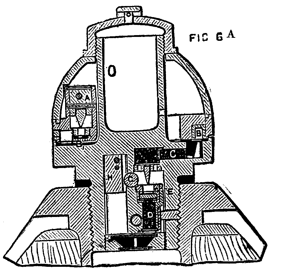
FIG. 6A.
The action is as follows: The ignition pellet, A, which is ordinarily held by a safety pin, is, after the withdrawal of the latter, only held by a fine, suspending wire, which is sheared by the inertia of the pellet on discharge, a needle lighting a percussion patch of composition and the composition ring, B B, which burns round at a given rate until it reaches the communication passage, C, when it flashes through the percussion pellet, E, and ignites the magazine, D, and so ignites the primer shown in Fig. 6, flashes down the central tube of the shell, and explodes the bursting charge in the base, Fig. 5. The length of time during which the fuse burns depends on how far the composition ring is turned round, and what length it consequently has to burn before it reaches the communication passage, C. If the fuse should be set too long, or from any other cause the shell strikes before the fuse fires the charge, the percussion action fires the shell on graze by the following arrangement: The heavy metal piece containing the magazine, D, constitutes a striker, which is held in place by a plain ball, G, near the axis of the fuse and by a safety pellet, H. On first movement in the gun, this latter by inertia shears a suspending wire and leaves the ball free to escape above it, which it does by centrifugal force, leaving the magazine striker, D, free to fire itself by momentum on the needle shown above it, on impact. There is a second safety arrangement, not shown in the figure, consisting of a cross pin, held by a weak spiral spring, which is compressed by centrifugal force during flight, leaving the magazine pellet free to act, as above described, on impact.
The armor-piercing projectile is shown in Fig. 7. It is to be made of forged steel, and supplied by Elswick. In appearance it very closely resembles those fired from the 100 ton gun at Spezia, but if it is made on the Firmini system, it will differ from it in the composition of its metal, inasmuch as it will contain a large proportion of chromium, probably from 1 to 2 per cent., whereas an analysis of Krupp's shell gives none. In fact, as Krupp's agent at Spezia predicted, the analysis is less instructive than we could wish.—The Engineer.
The industrial world has reason to feel considerable interest in any economical method of traction on railways, owing to the influence which cost of transportation has upon the price of produce. We give a description of the gas engine invented by Mr. Emmanuel Stevens. Many experiments have been made both at Berlin and Liege during the past few years. They all failed, owing to the impossibility the builders encountered in securing sufficient speed.
The Stevens engine does not present this defect, as will be seen. It has the appearance of an ordinary street car entirely inclosed, showing none of the machinery from without. On the interior is a Koerting gas motor of six horse power, which is a sufficiently well known type not to require a description. In the experiment which we saw, the motor was supplied with a mixture of gas and air, obtained by the evaporation of naphtha. On the shaft of the motor are fixed two pulleys of different sizes, which give the engine two rates of speed, one of three miles and the other of 8½ miles an hour. Between these two pulleys is a friction socket, by which either rate of speed may be secured.
The power is transmitted from one of the pulleys by a rubber belt to an intermediate shaft, which carries a toothed wheel that transmits the power to the axle by means of an endless chain. On this axle are three conical gear wheels, two of which are furnished with hooked teeth, and the third with wooden projections and fixed permanently in place. This arrangement enables the engine to be moved forward or backward according as it is thrown in right or left gear. When the conical pinions are thrown out of gear, the motive force is no longer applied to the axle, and by the aid of the brakes the engine may be instantly stopped. The movement of the pinions is effected by two sets of wheels on each of the platforms of the engine, and near the door for the conductor. By turning one of the wheels to the right or left on either platform, the conductor imparts either the less or the greater speed to the engine. In case he has caused the engine to move forward by turning the second wheel, he will not have to touch it again until the end of the trip. The brake, which is also operated from the two platforms, is applied to all four wheels at the same time. From this arrangement it is seen that the movement is continuous. Nevertheless, the conductor has access to the regulator by a small chain connected with the outside by a wheel near at hand, but the action is sufficiently regular not to require much attention to this feature.

GAS ENGINE FOR USE ON RAILROADS.
The gas is produced by the Wilford apparatus, which regularly furnishes the requisite quantity necessary for an explosion, which is produced by a particular kind of light placed near the piston. The vapor is produced by passing hot water from the envelope of the cylinder of the motor through the Wilford apparatus. The water is cooled again in a reservoir (system Koerting) placed in direct communication with the cylinder. Any permanent heating is therefore impossible.
The noise of the explosions is prevented by a device invented by Mr. Stevens himself. It consists of a drum covered with asbestos or any other material which absorbs noise.
According to the inventor, the saving over the use of horses for traction is considerable. This system is soon to be tried practically at Antwerp in Belgium, and then it will be possible to arrive at the actual cost of traction.—Industrie Moderne, Brussels.

LOCATION OVER THE BLUE RIDGE.—WESTERN NORTH CAROLINA RAILROAD.
The interesting piece of railroad location illustrated in this issue is on the mountain section of the Western North Carolina Railroad. This section crosses the Blue Ridge Mountains 18 miles east of Asheville, at a point known as Swannanoa Gap, 2,660 feet above tide water. The part of the road shown on the accompanying cut is 10 miles in length and has an elevation of 1,190 feet; to overcome the actual distance by the old State pike was somewhat over 3 miles. The maximum curvature as first located was 10°, but for economy of time as well as money this was exceeded in a few instances as the work progressed, but is now being by degrees reduced. The maximum grades on tangents are 116 feet per mile; on curves the grade is equated one-tenth to a degree. The masonry is of the most substantial kind, granite viaducts and arch culverts. The numbers and lengths of tunnels as indicated by letters on cut are as follows:
| Ft. in all of these. | |||||
| A. | Point Tunnel. | 216 | ft. | long.1 | |
| B. | Jarrett's Tunnel. | 125 | " | " | |
| C. | Lick Log Tunnel. | 562 | " | " | |
| D. | McElroy Tunnel. | 89 | " | " | |
| E. | High Ridge Tunnel. | 415 | " | " | |
| F. | Burgin Tunnel. | 202 | " | " | |
| G. | Swannanoa Tunnel. | 1,800 | " | " | |
The work was done by the State of North Carolina with convict labor, under the direction of Mr. Jas. A. Wilson, as president and chief engineer, but was sold by the State to the Richmond & Danville system.—Railroad Gazette.
[1]The new gasholder which has been erected by Messrs. C. and W. Walker for the Imperial Continental Gas Company at Erdberg, near Vienna, has been graphically described by Herr E.R. Leonhardt in a paper which he read before the Austrian Society of Engineers. The enormous dimensions and elegant construction of the holder—being the largest out of England—as well as the work of putting up the new gasholder, are of special interest to English engineers, as Erdberg contains the largest and best appointed works in Austria. The dimensions of the holder are—inner lift, 195 feet diameter, 40 feet deep; middle lift, 197½ feet diameter, 40 feet deep; outer lift, 200 feet diameter, 40 feet deep. The diameter over all is about 230 feet. The impression produced upon the members of the Austrian Society by their visit to Erdberg was altogether most favorable; and not only did the inspection of the large gasholder justify every expectation, but the visitors were convinced that all the buildings were in excellent condition and well adapted for their purpose, that the machinery was of the latest and most approved type, and that the management was in experienced hands.
is contained in a building consisting of a circular wall covered with a wrought iron roof. The holder itself is telescopic, and is capable of holding 3½ million cubic feet of gas. The accompanying illustrations (Figs. 1 and 3) are a sectional elevation of the holder and its house and a sectional plan of the roof and holder crown. Having a capacity of close upon 3,200,000 Austrian cubic feet, this gasholder is the largest of its kind on the Continent, and is surpassed in size by only a few in England and America. By way of comparison, Hamburg possesses a holder of 50,000 cubic meters (1,765,000 cubic feet) capacity; and there is one in Berlin which is expected to hold 75,000 cubic meters (2,647,500 cubic feet) of gas.
The gasholder house at Erdberg is perfectly circular, and has an internal diameter of 63.410 meters. It is constructed, in three stories, with forty piers projecting on the outside, and with four rows of windows between the piers—one in each of the top and bottom stories, and two rows in the middle. These windows have a height of 1.40 meters in the lowest circle, where the wall is 1.40 meters thick, and of 2.90 meters in the two top stories, where it is respectively 1.11 meters and 0.90 meter thick. The top edge of the wall is 35.35 meters above the base of the building, and 44.39 meters from the bottom of the tank; the piers rising 1.60 meters beyond the top of the wall. The highest point of the lantern on the roof will thus be 48.95 meters above the ground.
The tank in which the gasholder floats has an internal diameter of 61.57 meters, and therefore a superficial area of 3,000 square meters; and since the coping is 12.31 meters above the floor, it follows that the tank is capable of holding 35,500 cubic meters (7,800,000 gallons) of water. The bottom consists of brickwork 1.10 meters thick, rendered with Portland cement, and resting on a layer of concrete 1 meter thick. The walls are likewise of brick and cement, of a thickness of 3.30 meters up to the ground level, and 2.40 meters thick to the height of 3.44 meters above the surface. Altogether, 2,988,680 kilos. of cement and 5,570,000 bricks were used in its construction. In fact, from the bottom of tank to top of roof, it reaches as high as the monument at London Bridge.

FIG. 1.—SECTION OF GASHOLDER AND HOUSE.
The construction of the tank offered many and serious difficulties. The bottom of the tank is fully 3 meters below the level of the Danube Canal, which passes close by, and it was not until twelve large pulsometer pumps were set up, and worked continually night and day, that it was possible to reach the necessary depth to allow of the commencement of the foundations of the boundary wall.
The wrought iron cupola-shaped roof of the gasholder house was designed by Herr W. Brenner, and consists of 40 radiating rafters, each weighing about 25 cwt., and joined together by 8 polygonal circles of angle iron (90×90×10 mm.). The highest middle circle is uncovered, and carries a round lantern (Fig. 1). These radiating rafters consist of flat iron bars 7 mm. thick, and of a height which diminishes gradually, from one interval to another on the inside, from 252 to 188 mm. At the outside ends (varying from 80×80×9 mm. in the lowest to 60×60×7 mm. in the last polygon but one) these rafters are strengthened, at least as far as the five lowest ones are concerned, by flat irons tightly riveted on. At their respective places of support, the ends of all the spars are screwed on by means of a washer 250 mm. high and 31 mm. thick, and surmounted by a gutter supported by angle irons. From every junction between the radial rafters and the polygonal circle, diagonal bars are made to run to the center of the corresponding interval, where they meet, and are there firmly held together by means of a tongue ring. The roof is 64.520 meters wide and 14.628 meters high; and its total weight is 103.300 kilos. for the ironwork—representing a weight of 31.6 kilos. per square meter of surface. It is proposed to employ for its covering wooden purlins and tin plates. The whole construction has a light, pleasing, and yet thoroughly solid appearance.
Herr Brenner, the engineer of the Erdberg Works, gives a description of how the roof of a house, 54.6 meters wide, for a gasholder in Berlin, was raised to a height of 22 meters. In that instance the iron structure was put together at the bottom of the tank, leaving the rafter ends and the mural ring. The hoisting itself was effected by means of levers—one to each rafter—connected with the ironwork below by means of iron chains. At the top there were apertures at distances of about 26 mm. from each other, and through these the hoisting was proceeded with. With every lift, the iron structure was raised a distance of 26 mm.

FIG. 2.
Herr Brenner had considerable hesitation in raising in the same way the structure at Erdberg, which was much larger and heavier than that in Berlin. The simultaneous elevation to 48 meters above the level, proposed to be effected at forty different points, did not appear to him to offer sufficient security. He therefore proposed to put the roof together on the ground, and to raise it simultaneously with the building of the wall; stating that this mode would be perfectly safe, and would not involve any additional cost. The suggestion was adopted, and it was found to possess, in addition, the important advantage that the structure could be made to rest on the masonry at any moment; whereas this had been impossible in the case at the Berlin Gasworks.

FIG. 3.
At a given signal from the foreman, two operatives, stationed at each of the forty lifting points, with crowbars inserted in the holes provided for the purpose, give the screws a simultaneous turn in the same direction. The bars are then inserted in another hole higher up. The hoisting screws are connected with the structure of the roof, and rise therewith. All that is requisite for the hoisting from the next cross beam is to give a forward turn to the screws. When the workmen had become accustomed to their task, the hoisting to a distance of 1 meter occupied only about half to three-quarters of an hour. At the outset, and merely by way of a trial, the roof was lifted to a height of fully 2 meters, and left for some time suspended in the air. The eighty men engaged in the operation carry on the work with great regularity and steadiness, obeying the signal of the foreman as soon as it was given.
The holder, which was supplied by the well-known firm of Messrs. C. and W. Walker, of Finsbury Circus, London, and Donnington, Salop, was in an outer courtyard. It is a three-lift telescopic one; the lowest lift being 200 feet, the middle lift 197 ft. 6 in., and the top lift 195 ft. in diameter. The height of each lift is 40 feet. The several lifts are raised in the usual way; and they all work in a circle of 24 vertical U-shaped channel irons, fixed in the wall of the house by means of 13 supports placed at equal distances from the base to the summit (as shown in Fig. 2). When the gasholder is perfectly empty, the three lifts are inclosed, one in the other, and rest with their lower edges upon the bottom of the tank. In this case the roof of the top lift rests upon a wooden framework. Fixed in the floor of the tank are 144 posts, 9 inches thick at the bottom and 6 inches thick at the top, to support the crown of the holder in such a way that the tops are fixed in a kind of socket, each of them being provided with four horizontal bars, which decrease in thickness from 305 by 100 mm. to 150 by 50 mm., and represent 16 parallel polygons, which in their turn are fastened diagonally by means of iron rails 63 by 100 mm. thick, arranged crosswise. The top of this framework is perfectly contiguous with the inside of the crown of the gasholder. The crown itself is made up of iron plates, the outer rows having a thickness of 11 mm., decreasing to 5 mm. toward the middle, and to 3 mm. at the top. The plates used for the side sheets of the holder are: For the top and bottom rows, 6.4 mm.; and for the other plates, 2.6 mm.
A new bleaching compound has been discovered, consisting of three parts by measure of mustard-seed oil, four of melted paraffin, three of caustic soda 20° Baume, well mixed to form a soapy compound. Of this one part of weight and two of pure tallow soap are mixed, and of this mixture one ounce for each gallon of water is used for the bleaching bath, and one ounce caustic soda 20° Baume for each gallon is added, when the bath is heated in a close vessel, the goods entered, and boiled till sufficiently bleached.
Few persons, even among those best acquainted with our modern railroad system, are aware of the early struggles of the men to whose foresight, energy, and skill the new mode of transportation owes its introduction into this country. The railroad problem in the United States was quite a different one from that in Europe. Had we simply copied the railways of England, we should have ruined the system at the outset, for this country. In England, where the railroad had its origin, money was plenty, the land was densely populated, and the demand for rapid and cheap transportation already existed. A great many short lines connecting the great centers of industry were required, and for the construction of such in the most substantial manner the money was easily obtained. In America, on the contrary, a land of enormous extent, almost entirely undeveloped, but of great possibilities, lines of hundreds and even thousands of miles in extent were to be made, to connect cities as yet unborn, and accommodate a future traffic of which no one could possibly foresee the amount. Money was scarce, and in many districts the natural obstacles to be overcome were infinitely greater than any which had presented themselves to European engineers.
By the sound practical sense and the unconquerable will of George Stephenson, the numerous inventions which together make up the locomotive engine had been collected into a machine which, in combination with the improved roadway, was to revolutionize the transportation of the world. The railroad, as a machine, was invented. It remained to apply the new invention in such a manner as to make it a success, and not a failure. To do this in a new country like America required infinite skill, unbounded energy, the most careful study of local conditions, and the exercise of well matured, sound business judgment. To see how well the great invention has been applied in the United States, we have only to look at the network of iron roads which now reaches from the Great Lakes to the Gulf of Mexico, and from the Atlantic to the Pacific.
With all the experience we have had, it is not an easy problem, even at the present time, to determine how much money we are authorized to spend upon the construction of a given railroad. To secure the utmost benefit at the least outlay, regarding both the first cost of building the road and the perpetual cost of operating it, is the railroad problem which is perhaps less understood at the present day than any other. It was an equally important problem fifty years ago, and certainly not less difficult at that time. It was the fathers of the railroad system in the United States who first perceived the importance of this problem, and who, adapting themselves to the new conditions presented in this country, undertook to solve it. Among the pioneers in this branch of engineering no one has done more to establish correct methods, nor has left behind a more enviable or more enduring fame, than Major George W. Whistler.
The Whistler family is of English origin, and is found toward the end of the 15th century in Oxfordshire, at Goring and Whitchurch, on the Thames. One branch of the family settled in Sussex, at Hastings and Battle, being connected by marriage with the Websters of Battle Abbey, in which neighborhood some of the family still live. Another branch lived in Essex, from which came Dr. Daniel Whistler, President of the College of Physicians in London in the time of Charles the Second. From the Oxfordshire branch came Ralph, son of Hugh Whistler, of Goring, who went to Ireland, and there founded the Irish branch of the family, being the original tenant of a large tract of country in Ulster, under one of the guilds or public companies of the city of London. From this branch of the family came Major John Whistler, father of the distinguished engineer, and the first representative of the family in America. It is stated that in some youthful freak he ran away and enlisted in the British Army. It is certain that he came to this country during the Revolutionary War, under General Burgoyne, and remained with his command until its surrender at Saratoga, when he was taken prisoner of war. Upon his return to England he was honorably discharged, and, soon after, forming an attachment for a daughter of Sir Edward Bishop, a friend of his father, he eloped with her, and came to this country, settling at Hagerstown, in Maryland. He soon after entered the army of the United States, and served in the ranks, being severely wounded in the disastrous campaign against the Indians under Major-General St. Clair in the year 1791. He was afterward commissioned as lieutenant, rose to the rank of captain, and later had the brevet of major. At the reduction of the army in 1815, having already two sons in the service, he was not retained; but in recognition of his honorable record, he was appointed Military Storekeeper at Newport, Kentucky, from which post he was afterward transferred to Jefferson Barracks, where he lived to a good old age.
Major John Whistler had a large family of sons and daughters, among whom we may note particularly William, who became a colonel in the United States Army, and who died at Newport, Ky., in 1863; John, a lieutenant in the army, who died of wounds received in the battle of Maguago, near Detroit, in 1812; and George Washington, the subject of our sketch. Major John Whistler was not only a good soldier, and highly esteemed for his military services, but was also a man of refined tastes and well educated, being an uncommonly good linguist and especially noted as a fine musician. In his family he is stated to have united firmness with tenderness, and to have impressed upon his children the importance of a faithful and thorough performance of duty in whatever position they should be placed.
George Washington Whistler, the youngest son of Major John Whistler, was born on the 19th of May, in the year 1800, at Fort Wayne, in the present State of Indiana, but then part of the Northwest Territory, his father being at the time in command of that post. Of the boyhood of Whistler we have no record, except that he followed his parents from one military station to another, receiving his early education for the most part at Newport, Ky., from which place, on July 31, 1814, he was appointed a cadet to the United States Military Academy, being then fourteen years of age. The course of the student at West Point was a very satisfactory one. Owing to a change in the arrangement of classes after his entrance, he had the advantage of a longer term than had been given to those who preceded him, remaining five years under instruction. His record during his student life was good throughout. In a class of thirty members he stood No. 1 in drawing, No. 4 in descriptive geometry, No. 5 in drill, No. 11 in philosophy and in engineering, No. 12 in mathematics, and No. 10 in general merit. He was remarkable, says one who knew him at this time, for his frank and open manner and for his pleasant and cheerful disposition. A good story is told of the young cadet which shows his ability, even at this time, to make the best of circumstances apparently untoward, and to turn to his advantage his surroundings, whatever they might be. Having been for some slight breach of discipline required to bestride a gun in the campus for a short time, he saw, to his dismay, coming down the walk the beautiful daughter of Dr. Foster Swift, a young lady who, visiting West Point, had taken the hearts of the cadets by storm, and who, little as he may at the time have dreamed it, was destined to become his future wife. Pulling out his handkerchief, he bent over his gun, and appeared absorbed in cleaning the most inaccessible parts of it with such vigor as to be entirely unaware that any one was passing; nor did the young lady dream that a case of discipline had been before her until in after years, when, on a visit to West Point, an explanation was made to her by her husband.
It was at this time of his life that the refinement and taste for which Major Whistler was ever after noted began to show itself. An accomplished scientific musician and performer, he gained a reputation in this direction beyond that of a mere amateur, and scarcely below that of the professionals of the day. His sobriquet of "Pipes," which his skill upon the flute at this time gave him, adhered to him through life among his intimates in the army. His skill with the pencil, too, was something phenomenal, and would, had not more serious duties prevented, have made him as noted an artist as he was an engineer. Fortunately for the world this talent descended to one of his sons, and in his hands has had full development. These tastes in Major Whistler appeared to be less the results of study than the spontaneous outgrowth of a refined and delicate organization, and so far constitutional with him that they seemed to tinge his entire character. They continued to be developed till past the meridian of life, and amid all the pressure of graver duties furnished a most delightful relaxation.
Upon completing his course at the Military Academy he was graduated, July 1, 1819, and appointed second lieutenant in the corps of artillery. From this date until 1821 he served part of the time on topographical duty, and part of the time he was in garrison at Fort Columbus. From November 2, 1821, to April 30, 1822, he was assistant professor at the Military Academy, a position for which his attainments in descriptive geometry and his skill in drawing especially fitted him. This employment, however, was not altogether to his taste. He was too much of an artist to wish to confine himself to the mechanical methods needed in the training of engineering students. In 1822, although belonging to the artillery, he was detailed on topographical duty under Major (afterward Colonel) Abert, and was connected with the commission employed in tracing the international boundary between Lake Superior and the Lake of the Woods. This work continued four years, from 1822 to 1826, and subsequent duties in the cabinet of the commission employed nearly two years more.
The field service of this engagement was anything but light work, much of it being performed in the depth of winter with a temperature fifty degrees below zero. The principal food of the party was tallow and some other substance, which was warmed over a fire on stopping at night. The snow was then removed to a sufficient depth for a bed, and the party wrapped one another up in their buffalo robes, until the last man's turn came, when he had to wrap himself up the best he could. In the morning, after warming their food and eating, the remainder was allowed to harden in the pan, after which it was carried on the backs of men to the next stopping place. The work was all done upon snow-shoes, and occasionally a man became so blinded by the glare of the sun upon the snow that he had to be led by a rope.
Upon the 1st of June, 1821, Whistler was made second lieutenant in the First Artillery, in the reorganized army; on the 16th of August, 1821, he was transferred to the Second Artillery, and on the 16th of August, 1829, he was made first lieutenant. Although belonging to the artillery, he was assigned to topographical duty almost continually until December 31, 1833, when he resigned his position in the army. A large part of his time during this period was spent in making surveys, plans, and estimates for public works, not merely those needed by the national government, but others which were undertaken by chartered companies in different parts of the United States. There were at that time very few educated engineers in the country, besides the graduates of the Military Academy; and the army engineers were thus frequently applied for, and for several years government granted their services.
Prominent among the early works of internal improvement was the Baltimore & Ohio Railroad, and the managers of this undertaking had been successful in obtaining the services of several officers who were then eminent, or who afterward became so. The names of Dr. Howard, who, though not a military man, was attached to the Corps of Engineers, of Lieut.-Col. Long, and of Capt. William Gibbs McNeill appear in the proceedings of the company as "Chiefs of Brigade," and those of Fessenden, Gwynne, and Trimble among the assistants.
In October, 1828, this company made a special request for the services of Lieutenant Whistler. The directors had resolved on sending a deputation to England to examine the railroads of that country, and Jonathan Knight, William Gibbs McNeill, and George W. Whistler were selected for this duty. They were also accompanied by Ross Winans, whose fame and fortune, together with those of his sons, became so widely known afterward in connection with the great Russian railway. Lieutenant Whistler, says one who knew him well, was chosen for this service on account of his remarkable thoroughness in all the details of his profession, as well as for his superior qualifications in other respects. The party left this country in November, 1828, and returned in May, 1829.
In the course of the following year the organization of the Baltimore and Ohio Railroad, a part of which had already been constructed under the immediate personal supervision of Lieutenant Whistler, assumed a more permanent form, and allowed the military engineers to be transferred to other undertakings of a similar character. Accordingly, in June, 1830, Captain McNeill and Lieutenant Whistler were sent to the Baltimore and Susquehanna Railroad, for which they made the preliminary surveys and a definite location, and upon which they remained until about twenty miles were completed, when a lack of funds caused a temporary suspension of the work. In the latter part of 1831 Whistler went to New Jersey to aid in the construction of the Paterson and Hudson River Railroad (now a part of the Erie Railway). Upon this work he remained until 1833, at which time he moved to Connecticut to take charge of the location of the railroad from Providence to Stonington, a line which had been proposed as an extension of that already in process of construction from Boston to Providence.
In this year, December 31, 1833, Lieut. Whistler resigned his commission in the army, and this not so much from choice as from a sense of duty. Hitherto his work as an engineer appears to have been more an employment than a vocation. He carried on his undertakings diligently, as it was his nature to do, but without much anxiety or enthusiasm; and he was satisfied in meeting difficulties as they came up, with a sufficient solution. Henceforward he handled his profession from a love of it. He labored that his resources against the difficulties of matter and space should be overabundant, and if he had before been content with the sure-footed facts of observation, he now added the luminous aid of study. How luminous and how sure these combined became, his later works show best.
In 1834 Mr. Whistler accepted the position of engineer to the proprietors of locks and canals at Lowell. This position gave him among other things the direction of the machine shops, which had been made principally for the construction of locomotive engines. The Boston and Lowell Railroad, which at this time was in process of construction, had imported a locomotive from the works of George and Robert Stephenson, at Newcastle, and this engine was to be reproduced, not only for the use of the Lowell road, but for other railways as well, and to this work Major Whistler gave a large part of his time from 1834 to 1837. The making of these engines illustrated those features in his character which then and ever after were of the utmost value to those he served. It showed the self-denial with which he excluded any novelties of his own, the caution with which he admitted those of others, and the judgment which he exercised in selecting and combining the most meritorious of existing arrangements. The preference which he showed for what was simple and had been tried did not arise from a want of originality, as he had abundant occasion to show during the whole of his engineering life. He was, indeed, uncommonly fertile in expedients, as all who knew him testify, and the greater the demand upon his originality, the higher did he rise to meet the occasion. The time spent in Lowell was not only to the great advantage of the company, but it increased also his own stores of mechanical knowledge, and in a direction, too, which in later years was of especial value to him.
In 1837 the condition of the Stonington Railroad became such as to demand the continual presence and attention of the engineer. Mr. Whistler therefore moved to Stonington, a place to which he became much attached, and to which he seems during all of his wanderings to have looked with a view of making it finally his home. While engaged upon the above road he was consulted in regard to many other undertakings in different parts of the country, and prominent among these was the Western Railroad of Massachusetts.
This great work, remarkable for the boldness of its engineering, was to run from Worcester through Springfield and Pittsfield to Albany. To surmount the high lands dividing the waters of the Connecticut from those of the Hudson called for engineering cautious and skillful as well as heroic. The line from Worcester to Springfield, though apparently much less formidable, and to one who now rides over the road showing no very marked features, demanded hardly less study, as many as twelve several routes having been examined between Worcester and Brookfield. To undertake the solution of a problem of so much importance required the best of engineering talent, and we find associated on this work the names of three men who in the early railroad enterprises of this country stood deservedly in the front rank: George W. Whistler, William Gibbs McNeill, and William H. Swift. McNeill had graduated from the Military Academy in 1817, and rose to the rank of major in the Topographical Engineers. Like Whistler, he had been detailed to take charge of the design and construction of many works of internal improvement not under the direction of the general government. These two engineers exercised an influence throughout the country for many years much greater than that of any others. Indeed, there were very few works of importance undertaken at that time in connection with which their names do not appear. This alliance was further cemented by the marriage between Whistler and McNeill's sister. Capt. William H. Swift had also graduated from the Military Academy, and had already shown marked ability as an engineer. Such were the men who undertook the location and construction of the railroad which was to surmount the high lands between the Connecticut and the Hudson, and to connect Boston with the Great West.
The early reports of these engineers to the directors of the Western Railroad show an exceedingly thorough appreciation of the complex problem presented to them, and a much better understanding of the principles involved in establishing the route than seems to have been shown in many far more recent works. In these early reports made in 1836 and 1837, we find elaborate discussions as to the power of the locomotive engine, and a recognition of the fact that in comparing different lines we must regard the plan as well as the profile, "as the resistance from curves on a level road may even exceed that produced by gravity on an incline;" and in one place we find the ascents "equated at 18 feet, the slope which requires double the power needed on a level road," resulting in a "virtual increase." We find also a very clear expression of the fact that an increased expenditure in the power needed to operate the completed road may overbalance a considerable saving in first cost. To bear this principle in mind, and at the same time to work in accordance with the directors' ideas of economy, in a country where the railroad was regarded very largely as an experiment, was by no means an easy task. The temptation to make the first cost low at the expense of the quality of the road in running up the valley of Westfield River was very great, and the directors were at one time very strongly urged to make an exceedingly narrow and crooked road west of Springfield; but Major Whistler so convinced the President, Thomas B. Wales, of the folly of such a course, that the latter declared, with a most emphatic prefix, that he would have nothing to do with such a two-penny cow-path, and thus prevented its adoption.
Mr. Whistler had many investigations to make concerning the plans and policy of railroad companies at a time when almost everything connected with them was comparatively new and untried. When he commenced, there was no passenger railroad in the country, and but very few miles of quarry and mining track. If at that time an ascent of more than 1 in 200 was required, it was thought necessary to have inclined planes and stationary power. It was supposed that by frequent relays it would be possible to obtain for passenger cars a speed of eight or nine miles an hour. Almost nothing was known of the best form for rails, of the construction of the track, or of the details for cars or engines. In all of these things Major Whistler's highly gifted and well balanced mind enabled him to judge wisely for his employers, and to practice for them the truest economy.
Major Whistler's employment upon the Western Railroad began while he was still engaged upon the Stonington line. In connection with his friend McNeill he acted as consulting engineer for the Western road from 1836 to 1840. From 1840 to 1842 he was its chief engineer, with his headquarters at Springfield. The steep grades west of the Connecticut presented not only a difficult problem in location and construction, but in locomotive engineering as well. At the present day we can order any equipment which may best meet the requirement upon any railroad, and the order will be promptly met by any one of our great manufactories. But in the early days of the Western Railroad it was far otherwise, and the locomotive which should successfully and economically operate the hitherto unheard of grade of over 80 feet to the mile was yet to be seen. The Messrs. Winans, of Baltimore, had built some nondescript machines, which had received the name of "crabs," and had tried to make them work upon the Western road. But after many attempts they were given up as unfit for such service.
These "crabs" were eight wheeled engines, weighing about 20 tons, with a vertical boiler. The wheels were 3½ feet in diameter, but the engine worked on to an intermediate shaft, which was connected with the driving axle in such a way as to get the effect of a five foot wheel. These engines did not impress Major Whistler at all favorably. And it is related that one Sunday the watchman in charge of the building in which some of them were kept, hearing some one among the engines, went in quietly and overheard Major Whistler, apparently conversing with the "crab," and saying: "No; you miserable, top-heavy, lop-sided abortion of a grasshopper, you'll never do to haul the trains over this road." His experience in Lowell was here of great value to him, and he had become convinced that the engine of George Stephenson was in the main the coming machine, and needed but to be properly proportioned and of sufficient size to meet every demand.
With Major Whistler's work upon the Western Railroad his engineering service in this country concluded, and that by an occurrence which marked him as the foremost railroad engineer of his time. Patient, indefatigable, cautious, remarkable for exhaustless resource, admirable judgment, and the highest engineering skill, he had begun with the beginning of the railroad system, and had risen to the chief control of one of the greatest works in the world, the Western Railroad of Massachusetts. Not only had he shown the most far-sighted wisdom in fixing the general features of this undertaking, but no man surpassed him, if, indeed, any one equaled him, in an exact and thorough knowledge of technical details. To combine the various elements in such a manner as to produce the greatest commercial success, and to make the railroad in the widest sense of the word a public improvement, never forgetting the amount of money at his disposal, was the problem he had undertaken to solve. He had proved himself a great master in his profession, and had shown how well fitted he was to grapple with every difficulty. He was equally a man of science and a man of business. And to all this he added the most delicate sense of honor and the most spotless integrity. He was in the prime of manhood, and was prepared to enter upon the great work of his life.
It was not long after the introduction of the railroad that intelligent persons saw very plainly that the new mode of transportation was not to be confined to the working of an already established traffic, in densely populated regions, but that it would be of equal service in awakening the energies of undeveloped countries, in bringing the vast interior regions of the continents into communication with the seaboard, in opening markets to lands which before were beyond the reach of commerce. And it was seen, too, that in event of war, a new and invaluable element had been introduced, viz., the power of transportation to an extent never before imagined.
Especially were these advantages foreseen in the vast empire of Russia, and an attempt was very early made to induce private capitalists to undertake the construction of the lines contemplated in that country. The Emperor, besides guaranteeing to the shareholders a minimum profit of four per cent., proposed to give them, gratuitously, all the lands of the state through which the lines should pass, and to place at their disposal, also gratuitously, the timber and raw materials necessary for the way and works which might be found upon the ground. It was further proposed, to permit the importation of rails and of the rolling stock free of duty. Russian proprietors also came forward, and not only agreed to grant such portions of their land as the railroads might pass through, gratuitously, but further to dispossess themselves temporarily of their serfs, and surrender them to the use of the companies, on the sole condition that they should be properly supported while thus employed.
With regard to the great line, however, which was to unite the two capitals, St. Petersburg and Moscow, it was decreed that this should be made exclusively at the expense of the state, in order to retain in the hands of the government and in the general interest of the people a line of communication so important to the industry and the internal commerce of the country. The local proprietors agreed to surrender to the government, gratuitously, the lands necessary for this line.
It was very early understood that the railroad problem in Russia was much more analogous to that in the United States than to that in England. The Emperor, therefore, in 1839, sent the Chevalier De Gerstner to the United States to obtain information concerning the railroads of this country. It was this person who obtained from the Emperor the concession for the short railway from St. Petersburg to Zarskoe Selo, which had been opened in 1837, and who had also made a careful reconnoissance in 1835 for a line from St. Petersburg to Moscow, and had very strongly urged its construction on the American plan. The more De Gerstner examined our roads, the more impressed he was with the fitness of what he termed the American system of building and operating railroads to the needs of the empire of Russia. In one of his letters in explaining the causes of the cheap construction of American railroads, after noting the fact that labor as well as material is much dearer in America than in Europe, he refers to the use of steep grades (93 feet to the mile) and sharp curves (600 feet radius), upon which the American equipment works easily, to the use of labor saving machinery, particularly to a steam excavating machine upon the railroad between Worcester and Springfield, and to the American system of wooden bridge building, and says: "The superstructure of the railroads in America is made conformable to the expected traffic, and costs therefore more or less accordingly;" and he concludes, "considering the whole, it appears that the cheapness of the American railroads has its foundation in the practical sense which predominates in their construction." Again, under the causes of the cheap management of the American roads, he notes the less expensive administration service, the low rate of speed, the use of the eight wheeled cars and the four-wheeled truck under the engines, and concludes: "In my opinion it would be of great advantage for every railroad company in Europe to procure at least one such train" (as those used in America). "Those companies, however, whose works are yet under construction I can advise with the fullest conviction to procure all their locomotive engines and tenders from America, and to construct their cars after the American model."
Notwithstanding this report, the suggestions of De Gerstner were not at once accepted. The magnitude of the enterprise would not admit of taking a false step. Further evidence was needed, and accordingly it was decided to send a committee of engineer officers to various countries in Europe, and to the United States, to select such a system for the road and its equipment as would be best adapted to Russia. These officers, Colonels Melnikoff and Krofft, not only reported in the most decided manner in favor of the American methods, but also stated that of all persons with whom they had communicated, no one had given them such full and satisfactory information upon all points, or had so impressed them as possessing extraordinary ability, as Major George W. Whistler. This led to his receiving an invitation from the Emperor to go to Russia and become consulting engineer for the great road which was to connect the imperial city upon the Baltic with the ancient capital of the Czars.
When we consider the magnitude of the engineering works with which the older countries abound, we can but regard with a feeling of pride the fact that an American should have been selected for so high a trust by a European government possessing every opportunity and means for securing the highest professional talent which the world could offer. Nor should it be forgotten that the selection of our countryman did not arise from any necessity which the Russian Government felt for obtaining professional aid from abroad, growing out of a lack of the requisite material at home. On the contrary, the engineers of the Russian service are perhaps the most accomplished body of men to be found in any country. Selected in their youth, irrespective of any artificial advantages of birth or position, but for having a genius for such work, and trained to a degree of excellence in all of the sciences unsurpassed in any country, they stand deservedly in the front rank. Such was the body of men with whom Major Whistler was called to co-operate, and whose professional duties, if not directed specially by him, were to be controlled by his judgment.
Accepting the position offered to him in so flattering a manner, he sailed for St. Petersburg about mid-summer in 1842, being accompanied on his voyage by Major Bouttattz, of the Russian Engineer Corps, who had been sent to this country by the Emperor as an escort. Arriving in St. Petersburg, and having learned the general character of the proposed work, he traveled partly by horse and partly on foot over the entire route, and made his preliminary report, which was at once accepted.
The plan contemplated the construction of a double track railroad 420 miles long, perfect in all its parts, and equipped to its utmost necessity. The estimates amounted to nearly forty millions of dollars, and the time for its construction was reckoned at seven years. The line selected for the road had no reference to intermediate points, and was the shortest attainable, due regard being paid to the cost of construction. It is nearly straight, and passes over so level a country as to encounter no obstacle requiring a grade exceeding 20 feet to the mile, and for most of the distance it is level. The right of way taken was 400 feet in width throughout the entire length. The roadbed was raised from six to ten feet above the ordinary level of the country, and was 30 feet wide on top.
One of the most important questions to settle at the outset in regard to this great work was the width of the gauge. At that time the opinion in England as well as in the United States among engineers was setting very strongly in favor of a gauge wider than 4 feet 8½ inches, and the Russian engineers were decidedly in favor of such increased width. Major Whistler, however, in an elaborate report to the Count Kleinmichel argued very strongly in favor of the ordinary gauge. To this a commission of the most distinguished engineers in Russia replied, urging in the most forcible manner the adoption of a gauge of six feet. Major Whistler rejoined in a report which is one of the finest models of an engineering argument ever written, and in which we have perhaps the best view of the quality of his mind. In this document no point is omitted, each part of the question is handled with the most consummate skill, the bearing of the several parts upon the whole is shown in the clearest possible manner, and in a style which could only come from one who from his own knowledge was thoroughly familiar with all the details, not only of the railroad, but of the locomotive as well.
In this report the history of the ordinary gauge is given, with the origin of the standard of 4 feet 8½ inches; the questions of strength, stability, and capacity of cars, of the dimensions, proportions, and power of engines, the speed of trains, resistances to motion, weight and strength of rails, the cost of the roadway, and the removal of snow are carefully considered. The various claims of the advocates for a wider gauge are fairly and critically examined, and while the errors of his opponents are laid bare in the most unsparing manner, the whole is done in a spirit so entirely unprejudiced, and with so evident a desire for the simple truth, as to carry conviction to any fair minded person. The dry way, too, in which he suggests that conclusions based upon actual results from existing railways are of more value than deductions from supposed conditions upon imaginary roads, is exceedingly entertaining. The result was the adoption of the gauge recommended by him, namely, five feet. Those who remember the "Battle of the Gauges," and who know how much expense and trouble the wide gauge has since caused, will appreciate the stand taken thus early by Major Whistler; and this was but one among many cases which might be mentioned to show how comprehensive and far-reaching was his mind.
The roadbed of the St. Petersburg and Moscow Railway was made 30 feet wide on top, for a double track of 5 foot gauge, with a gravel ballasting two feet deep. The bridges were of wood, of the Howe pattern, no spans being over 200 feet in length. The stations at each end, and the station and engine houses along the line, were on a plan uniform throughout, and of the most ample accommodation. Fuel and water stations were placed at suitable points, and engine houses were provided 50 miles apart, built of the most substantial masonry, circular in form, 180 feet in diameter, surmounted by a dome, and having stalls for 22 engines each. Repair shops were attached to every engine house, furnished with every tool or implement that the wants of the road could suggest.
The equipment of rolling stock and fixed machinery for the shops was furnished by the American firm of Winans, Harrison & Eastwick, who from previous acquaintance were known by Major Whistler to be skillful, energetic, and reliable. Much diplomacy was needed to procure the large money advances for this part of the work, the whole Winans contract amounting to nearly five millions of dollars; but the assurance of Major Whistler was a sufficient guarantee against disappointment or failure.
In 1843 the plans for the work were all complete, and in 1844 the various operations along the line were well under way, and proceeding according to the well arranged programme. In 1845 the work had progressed so far that the construction of the rolling stock was commenced. The locomotives were of two classes, freight and passenger. The engines of each class were made throughout from the same patterns, so that any part of one engine would fit the same position on any other. The passenger engines had two pairs of driving wheels, coupled, 6 feet in diameter, and a four wheeled truck similar to the modern American locomotive. The general dimensions were: Waist of boiler, 47 inches, 186 two inch tubes 10½ feet long; cylinders, 16 × 22 inches. The freight engines had the same capacity of boiler and the same number and length of tubes, three pairs of driving wheels, coupled, 4½ feet in diameter, a truck and cylinders 18 × 22 inches, and all uniform throughout in workmanship and finish. The passenger cars were 56 feet long and 9½ feet wide, the first class carrying 33 passengers, the second class 54, and the third class 80. They all had eight truck wheels under each, and elliptic steel springs. The freight cars were all 30 feet long and 9½ feet wide, made in a uniform manner, with eight truck wheels under each. The imperial saloon carriages were 80 feet long and 9½ feet wide, having double trucks, or sixteen wheels under each. They were divided into five compartments and fitted with every convenience.
Early in 1847 the Emperor Nicholas visited the mechanical works at Alexandroffsky, where the rolling stock was being made by the Messrs. Winans, in the shops prepared by them and supplied by Russian labor. Everything here was on the grandest scale, and the work was conducted under the most perfect system. Upon this occasion the Emperor was so much gratified at what had already been accomplished that he conferred upon Major Whistler the decoration of the Order of St. Anne. He had previously been pressed to wear the Russian uniform, which he promptly declined to do; but there was no escape from the decoration without giving offense. He is said, however, to have generally contrived to hide it beneath his coat in such a manner that few ever saw it.
Technically, Major Whistler was consulting engineer, Colonel Melnikoff being constructing engineer for the northern half of the road, and Colonel Krofft for the southern half; but as a matter of fact, by far the larger part of planning the construction in detail of both railway and equipment fell upon Major Whistler. There was also a permanent commission having general charge of the construction of the road, of which the president was General Destrem, one of the four French engineers whom Napoleon, at the request of the Emperor Alexander, sent to Russia for the service of that country.
The year 1848 was a very trying one to Major Whistler. He had already on several occasions overtasked his strength, and had been obliged to rest. This year the Asiatic cholera made its appearance. He sent his family abroad, but remained himself alone in his house. He would on no account at this time leave his post, nor omit his periodical inspections along the line of the road, where the epidemic was raging. In November he had an attack of cholera, and while he recovered from it, he was left very weak. Still, he remained upon the work through the winter, though suffering much from a complication of diseases. As spring advanced he became much worse, and upon the 7th of April, 1849, he passed quietly away, the immediate cause of his death being a trouble with the heart.
Funeral services were held in the Anglican (Episcopal) Church in St. Petersburg. His body was soon afterward carried to Boston and deposited beneath St. Paul's Church; but the final interment took place at Stonington. The kindness and attention of the Emperor and of all with whom Major Whistler had been associated knew no bounds. Everything was done to comfort and aid his wife, and when she left St. Petersburg the Emperor sent her in his private barge to the mouth of the Baltic. "It was not only," says one who knew him weil, "through his skill, ability, and experience as an engineer that Major Whistler was particularly qualified for and eminently successful in the important task he performed so well in Russia. His military training and bearing, his polished manner, good humor, sense of honor, knowledge of a language (French) in which he could converse with officers of the government, his resolution in adhering to what he thought was right, and in meeting difficulties only to surmount them, with other admirable personal qualities, made him soon, and during his whole residence in Russia, much liked and trusted by all persons by whom he was known, from the Emperor down to the peasant. Such is the reputation he left behind him, and which is given to him in Russia to this day."
In 1849 the firm of Winans, Harrison and Eastwick had already furnished the road with 162 locomotives, 72 passenger and 2,580 freight cars. They had also arranged to instruct a suitable number of Russian mechanics to take charge of the machinery when completed. The road was finished its entire length in 1850, being opened for passenger and freight traffic on the 25th of September of that year, in two divisions, experimentally, and finally opened for through business on November 1, 1851. In all of its construction and equipment it was essentially American of the best kind, everything being made under a carefully devised system, by which the greatest economy in maintenance and in management should be possible. The use of standard patterns, uniformity in design and duplication of parts was applied, not only to the rolling stock, but to the railroad as well, wherever it was possible. Indeed, the whole undertaking in all its parts bore the impress of one master mind.
On the death of Major Whistler the government with jealous care prevented any changes whatever being made in his plans, including those which had not been carried out as well as those already in process of execution. An American engineer, Major T.S. Brown, was invited to Russia to succeed Major Whistler as consulting engineer. The services of the Messrs. Winans also were so satisfactory to the government that a new contract was afterward made, upon the completion of the road, for the maintenance and the future construction of rolling stock.
While the great railroad was the principal work of Major Whistler in Russia, he was also consulted in regard to all the important engineering works of the period. The fortifications at Cronstadt, the Naval Arsenal and docks at the same place, the plans for improving the Dwina at Archangel, the great iron roof of the Riding House at St. Petersburg, and the iron bridge over the Neva all received his attention. The government was accustomed to rely upon his judgment in all cases requiring the exercise of the highest combination of science and practical skill; and here, with a happy tact peculiarly his own, he secured the warm friendship of men whose professional acts he found himself called upon in the exercise of his high trust in many cases to condemn. The Russians are proverbially jealous of strangers, and no higher evidence of their appreciation of the sterling honesty of Major Whistler, and of his sound, discriminating judgment, could be afforded than the fact that all his recommendations on the great questions of internal improvement, opposed as many of them were to the principles which had previously obtained, and which were sanctioned by usage, were yet carried out by the government to the smallest details.
While in Russia Major Whistler was sometimes placed in positions most trying to him. It is said that some of the corps of native engineers, many of whom were nobles, while compelled to look up to him officially, were inclined to look down upon him socially, and exercised their supposed privileges in this respect so as to annoy him exceedingly, for he had not known in his own country what it was to be the social inferior of any one. The Emperor, hearing of this annoyance, determined to stop it; so, taking advantage of a day when he knew the engineer corps would visit a celebrated gallery of art, he entered it while they were there, and without at first noticing any one else, looked around for Major Whistler, and seeing him, went directly toward him, took his arm, and walked slowly with him entirely around the gallery. After this the conduct of the nobles was all that could be desired.
Major Whistler's salary while in Russia was $12,000 a year; a sum no more than necessary for living in a style befitting his position. He had abundant opportunity for making money, but this his nice sense of honor forbade. It is even stated that he would never allow any invention to be used on the road that could by any possibility be of any profit to himself or to any of his friends. He was continually besieged by American inventors, but in vain. The honor of the profession he regarded as a sacred trust. He served the Emperor with the fidelity that characterized all his actions. His unswerving devotion to his duty was fully appreciated, and it is said that no American in Russia, except John Quincy Adams, was ever held in so high estimation.
Major Whistler married for his first wife Mary, daughter of Dr. Foster Swift of the U.S. Army, and Deborah, daughter of Capt. Thomas Delano of Nantucket. By her he had three children: Deborah, his only daughter, who married Seymour Haden of London, a surgeon, but later and better known for his skill in etching; George William, who became an engineer and railway manager, and who went to Russia, and finally died at Brighton, in England, Dec. 24, 1869; Joseph Swift, born at New London, Aug. 12, 1825, and who died at Stonington, Jan. 1, 1840. His first wife died Dec. 9, 1827, at the early age of 23 years, and is buried in Greenwood Cemetery, in the shade of the monument erected to the memory of her husband by the loving hands of his professional brethren. For his second wife he married Anna Matilda, daughter of Dr. Charles Donald McNeill of Wilmington, N.C., and sister of his friend and associate, William Gibbs McNeill. By her he had five sons: James Abbot McNeill, the noted artist, and William Gibbs McNeill, a well known physician, both now living in London; Kirk Boott, born in Stonington, July 16, 1838, and who died at Springfield, July 10, 1842; Charles Donald, born in Springfield, Aug. 27, 1841, and who died in Russia, Sept. 24, 1843; and John Bouttattz, who was born and who died at St. Petersburg, having lived but little more than a year. His second wife, who outlived him, returned to America, and remained here during the education of her children, after which she moved to England. She died Jan. 31, 1881, at the age of 76 years, and was buried at Hastings.
At a meeting held in the office of the Panama Railroad Company in New York, August 27, 1849, for the purpose of suggesting measures expressive of their respect for the memory of Major Whistler, Wm. H. Sidell being chairman and A.W. Craven secretary, it was resolved that a monument in Greenwood Cemetery would be a suitable mode of expressing the feelings of the profession in this respect, and that an association be formed to collect funds and take all necessary steps to carry out the work. At this meeting Capt. William H. Swift was appointed president, Major T.S. Brown treasurer, and A.W. Craven secretary, and Messrs. Horatio Allen, W.C. Young, J.W. Adams, and A.W. Craven were appointed a committee to procure designs and estimates, and to select a suitable piece of ground. The design was made by Mr. Adams, and the ground was given by Mr. Kirkwood. The monument is a beautiful structure of red standstone, about 15 feet high, and stands in "Twilight Dell." Upon the several faces are the following inscriptions:
Upon the Front.
IN MEMORY OF
GEORGE WASHINGTON WHISTLER,
CIVIL ENGINEER,
BORN AT FORT WAYNE, INDIANA, MAY, 1800,
DIED AT ST. PETERSBURG, RUSSIA, APRIL, 1849.
Upon the Right Side.
EDUCATED AT THE U.S. MILITARY ACADEMY. HE
RETIRED FROM THE ARMY IN 1833 AND BECAME
ASSOCIATED WITH WILLIAM GIBBS M'NEILL.
THEY WERE IN THEIR TIME ACKNOWLEDGED TO
BE AT THE HEAD OF THEIR PROFESSION IN THIS
COUNTRY.
Upon the Back.
HE WAS DISTINGUISHED FOR THEORETICAL AND
PRACTICAL ABILITY, COUPLED WITH SOUND
JUDGMENT AND GREAT INTEGRITY. IN 1842 HE
WAS INVITED TO RUSSIA BY THE EMPEROR
NICHOLAS, AND DIED THERE WHILE CONSTRUCTING
THE ST. PETERSBURG & MOSCOW RAILROAD.
Upon the Left Side.
THIS CENOTAPH IS A MONUMENT OF THE ESTEEM
AND AFFECTION OF HIS FRIENDS AND COMPANIONS.
While the monument thus raised to the memory of the great engineer stands in that most delightful of the cities of the dead, his worn-out body rests in the quaint old town of Stonington. It was here that his several children had been buried, and he had frequently expressed a desire that when he should die he might be placed by their side. A deputation of engineers who had been in their early years associated with him attended the simple service which was held over his grave, and all felt as they turned away that they had bid farewell to such a man as the world has not often seen.
In person Major Whistler was of medium size and well made. His face showed the finest type of manly beauty, combined with a delicacy almost feminine. In private life he was greatly prized for his natural qualities of heart and mind, his regard for the feelings of others, and his unvarying kindness, especially toward his inferiors and his young assistants. His duties and his travels in this and in other countries brought him in contact with men of every rank; and it is safe to say that the more competent those who knew him were to judge, the more highly was he valued by them. A close observer, with a keen sense of humor and unfailing tact, fond of personal anecdote, and with a mind stored with recollections from association with every grade of society, he was a most engaging companion. The charm of his manner was not conventional, nor due to intercourse with refined society, but came from a sense of delicacy and a refinement of feeling which was innate, and which showed itself in him under all circumstances. He was in the widest and best sense of the word a gentleman; and he was a gentleman outwardly because he was a gentleman at heart.
As an engineer, Whistler's works speak for him. He was eminently a practical man, remarkable for steadiness of judgment and for sound business sense. Whatever he did was so well done that he was naturally followed as a model by those who were seeking a high standard. Others may have excelled in extraordinary boldness or in some remarkable specialty, but in all that rounds out the perfect engineer, whether natural characteristics, professional training, or the well digested results of long and valuable experience, we look in vain for his superior, and those who knew him best will hesitate to acknowledge his equal.—Journal of the Association of Engineering Societies.
[1]There can be no question that there is no plan that is so simple for producing transparencies as contact printing, but in this, as in other photographic matters, one method of work will not answer all needs. Reproduction in the camera, using daylight to illuminate the negative, enables the operator to reduce or enlarge in every direction, but the lantern is a winter instrument, and comes in for demand and use during the short days. When even the professional photographer has not enough light to get through his orders, how can the amateur get the needed daylight if photography be only the pursuit in spare time? Besides, there are days in our large towns when what daylight there is is so yellow from smoke or fog as to have little actinic power. These considerations and needs have led me to experiment and test what can be done with artificial light, and I think I have made the way clear for actual work without further experiment. I have not been able by any arrangement of reflected light to get power enough to print negatives of the ordinary density, and have only succeeded by causing the light to be equally dispersed over the negative by a lens as used in the optical lantern, but the arrangements required are somewhat different to that of the enlarging lantern.
The following is the plan by which I have succeeded best in the production of transparencies:
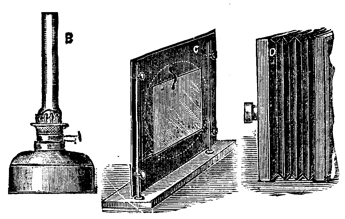
B is a lamp with a circular wick, which burns petroleum and gives a good body of light.
C is a frame for holding the negative, on the opposite side of which is a double convex lens facing the light.
D is the camera and lens.
All these must be placed in a line, so that the best part of the light, the center of the condenser, and the lens are of equal height.
The method of working is as follows: The lamp, B, is placed at such a distance from the condenser that the rays come to a focus and enter the lens; the negative is then placed in the frame, the focus obtained, and the size of reduction adjusted by moving the camera nearer to or further from the condenser and negative. In doing this no attention need be paid to the light properly covering the field, as that cannot be adjusted while the negative is in its place. When the size and focus are obtained, remove the negative, and carefully move the lamp till it illuminates the ground glass equally all over, by a disk of light free from color.
The negative can then be replaced, and no further adjustment will be needed for any further reproduction of the same size.
There is one point that requires attention: The lens used in the camera should be a doublet of about 6 inch focus (in reproducing 8½ × 6½ or smaller sizes), and the stop used must not be a very small one, not less than ½ inch diameter. If a smaller stop is used, an even disk of light is not obtained, but ample definition is obtainable with the size stop mentioned.
In the arrangement described, a single lens is used for the condenser, not because it is better than a double one, as is general for such purposes, but because it is quite sufficient for the purpose. Of course, a large condenser is both expensive and cumbersome. There is, therefore, no advantage in using a combination if a single lens will answer.
In reproducing lantern pictures from half-plate negatives, the time required on my lantern plates is from two to four minutes, using 6 inch condenser. For whole plate negatives, from two to six minutes with a 9 inch condenser. In working in this way it is easy to be developing one picture while exposing another.
The condenser must be of such a size that it will cover the plate from corner to corner. The best part of an 8½ × 6½ negative will be covered by a 9 inch condenser, and a 6½ × 4¾ by a 6 inch condenser.
With this arrangement it will be easy to reproduce from half or whole plate negatives or any intermediate sizes quite independently of daylight.
[1]From the Photographic News we take the following: The use of paper coated with a gelatino-citro-chloride emulsion in place of albumenized paper appears to be becoming daily more common. Successful toning has generally been the difficulty with such paper, the alkaline baths commonly in use with albumenized having proved unsuitable for toning this paper. On the whole, the bath that has given the best results is one containing, in addition to gold, a small quantity of hypo and a considerable quantity of sulphocyanide of ammonium. Such a bath tones very rapidly, and gives most pleasing colors. It appears, moreover, to be impossible to overtone the citro-chloro emulsion paper with it in the sense that it is possible to overtone prints on albumenized paper with the ordinary alkaline bath. That is to say, it is impossible to produce a slaty gray image. The result of prolonged toning is merely an image of an engraving black color. Of this, however, we shall say more hereafter. We wish first of all to refer to an elaborate series of experiments by Lionel Clark on the effects of various toning baths used with the gelatino-citro-chloride paper.
The results of these experiments we have before us at the time of writing, and we may at once say that, from the manner in which the experiments have been carried out and in which the results have been tabulated, Lionel Clark's work forms a very useful contribution to our photographic knowledge, and a contribution that will become more and more useful, the longer the results of the experiments are kept. A number of small prints have been prepared. Of these several—in most cases, three—have been toned by a certain bath, and each print has been torn in two. One-half has been treated with bichloride of mercury, so as to bleach such portion of the image as is of silver, and finally the prints—the two halves of each being brought close together—have been mounted in groups, each group containing all the prints toned by a certain formula, with full information tabulated.
The only improvement we could suggest in the arrangement is that all the prints should have been from the same negative, or from only three negatives, so that we should have prints from the same negatives in every group, and should the better be able to compare the results of the toning baths. Probably, however, the indifferent light of the present season of the year made it difficult to get a sufficiency of prints from one negative.
The following is a description of the toning baths used and of the appearance of the prints. We refer, in the mean time, only to those halves that have not been treated with bichloride of mercury.
1.——Gold chloride (AuCl₃)..............  1 gr.
    Sulphocyanide of potassium......... 10 gr.
    Hyposulphite of soda...............  ½ gr.
    Water..............................  2 oz.
The prints are of a brilliant purple or violet color.
2.——Gold chloride......................  1 gr.
    Sulphocyanide of potassium......... 10 gr.
    Hyposulphite of soda...............  ½ gr.
    Water..............................  4 oz.
There is only one print, which is of a brown color, and in every way inferior to those toned with the first bath.
3.——Gold chloride......................  1 gr.
    Sulphocyanide of potassium......... 12 gr.
    Hyposulphite of soda...............  ½ gr.
    Water..............................  2 oz.
The prints toned by this bath are, in our opinion, the finest of the whole. The tone is a purple of the most brilliant and pleasing shade.
4.——Gold chloride......................  1 gr.
    Sulphocyanide of potassium......... 20 gr.
    Hyposulphite of soda...............  5 gr.
    Water..............................  2 oz.
There is only one print, but it is from the same negative as one of the No. 3 group. It is very inferior to that in No. 3, the color less pleasant, and the appearance generally as if the details of the lights had been bleached by the large quantity either of hypo or of sulphocyanide of potassium.
5.——Gold chloride......................  1 gr.
    Sulphocyanide of potassium......... 50 gr.
    Hyposulphite of soda...............  ½ gr.
    Water..............................  2 oz.
Opposite to this description of formula there are no prints, but the following is written: "These prints were completely destroyed, the sulphocyanide of potassium (probably) dissolving off the gelatine."
6.——Gold chloride......................  1 gr.
    Sulphocyanide of potassium......... 20 gr.
    Hypo...............................  5 gr.
    Carbonate of soda.................. 10 gr.
    Water..............................  2 oz.
This it will be seen is the same as 4, but that the solution is rendered alkaline with carbonate of soda. The result of the alkalinity certainly appears to be good, the color is more pleasing than that produced by No. 4, and there is less appearance of bleaching. It must be borne in mind in this connection that the paper itself is strongly acid, and that, unless special means be taken to prevent it, the toning bath is sure to be more or less acid.
7.——Gold chloride......................  1 gr.
    Acetate of soda.................... 30 gr.
    Water..............................  2 oz.
The color of the prints toned by this bath is not exceedingly pleasing. It is a brown tending to purple, but is not very pure or bright. The results show, however, the possibility of toning the gelatino-chloro-citrate paper with the ordinary acetate bath if it be only made concentrated enough.
8.——Gold chloride......................  1 gr.
    Carbonate of soda..................  3 gr.
    Water..............................  2 oz.
Very much the same may be said of the prints toned by this bath as of those toned by No. 7. The color is not very good, nor is the toning quite even. This last remark applies to No. 7 batch as well as No. 8.
9.——Gold chloride......................  1 gr.
    Phosphate of soda.................. 20 gr.
    Water..............................  2 oz.
The results of this bath can best be described as purplish in color. They are decidedly more pleasing than those of 7 or 8, but are not as good as the best by the sulphocyanide bath.
10.——Gold chloride.....................  1 gr.
     Hyposulphite of soda..............  ½ oz.
     Water.............................  2 oz.
The result of this bath is a brilliant brown color, what might indeed, perhaps, be best described as a red. Two out of the three prints are much too dark, indicating, perhaps, that this toning bath did not have any tendency to reduce the intensity of the image.
The general lesson taught by Clark's experiments is that the sulphocyanide bath gives better results than any other. A certain proportion of the ingredients—namely, that of bath No. 3—gives better results than any other proportions tried, and about as good as any that could be hoped for. Any of the ordinary alkaline toning baths may be used, but they all give results inferior to those got by the sulphocyanide bath. The best of the ordinary baths is, however, the phosphate of soda.
And now a word as to those parts of the prints which have been treated with bichloride of mercury. The thing that strikes us as remarkable in connection with them is that in them the image has scarcely suffered any reduction of intensity at all. In most cases there has been a disagreeable change of color, but it is almost entirely confined to the whites and lighter tints, which are turned to a more or less dirty yellow. Even in the case of the prints toned by bath No. 10, where the image is quite red, it has suffered no appreciable reduction of intensity.
This would indicate that an unusually large proportion of the toned image consists of gold, and this idea is confirmed by the fact that to tone a sheet of gelatino-chloro-citrate paper requires several times as much gold as to tone a sheet of albumenized paper. Indeed, we believe that, with the emulsion paper, it is possible to replace the whole of the silver of the image with gold, thereby producing a permanent print. We have already said that the print may be left for any reasonable length of time in the toning bath without the destruction of its appearance, and we cannot but suppose that a very long immersion results in a complete substitution of gold for silver.
Fig. 1 shows a perspective view of the machine, Fig. 2 a sectional elevation, and Fig. 3 a plan. In the ordinary screw gill box, the screws which traverse the gills are uniform in their pitch, so that a draught is only obtained between the feed rollers and the first gill, between the last gill of the first set and the first of the second, and between the last gill of the second set and the delivery roller. As thus arranged, the gills are really not active workers after their first draw during the remainder of their traverse, but simply carriers of the wool to the next set. It is somewhat remarkable, as may indeed be said of every invention, that this fact has only been just observed, and suggested an improvement. There is no reason why each gill should not be continuously working to the end of the traverse, and only cease during its return to its first position. The perception of this has led to several attempts to realize this improvement. The inventor in the present case seems to have solved the problem in a very perfect manner by the introduction of gill screws of a gradually increasing pitch, by which the progress of the gills, B, through the box is constantly undergoing acceleration to the end, as will be obvious from the construction of the screws, A and A¹, until they are passed down in the usual manner, and returned by the screws, C and C¹, which are, as usual, of uniform pitch. The two sets of screws are so adjusted as to almost meet in the middle, so that the gills of the first set finish their forward movement close to the point where the second commence. The bottom screws, C, of the first set of gills, B, are actuated by bevel wheels on a cross shaft engaging with bevel wheels on their outer extremity, the cross shaft being geared to the main shaft. The screws, C¹, of the second set of gills from two longitudinal shafts are connected by bevel gearing to the main shaft. Intermediate wheels communicate motion from change wheels on the longitudinal shafts to the wheels on the screw, C¹, traversing the second set of gills.
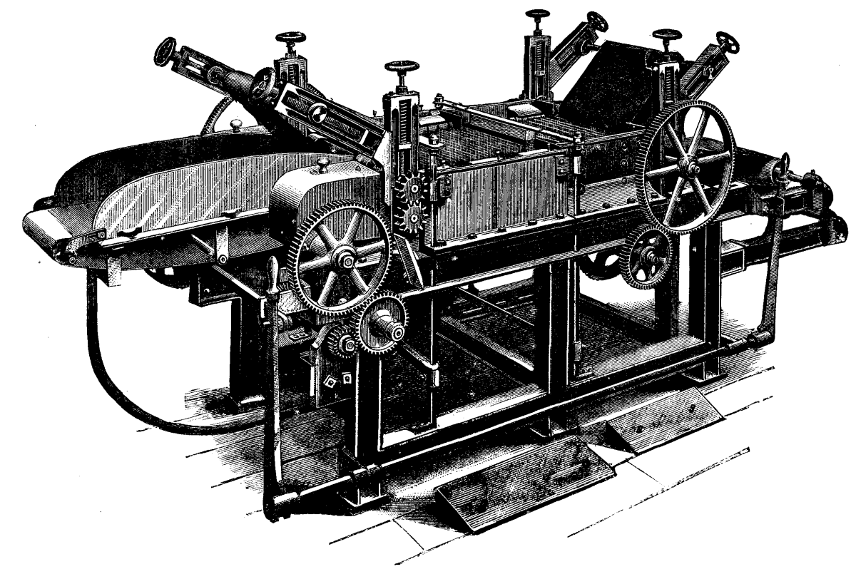
FIG. 1.—"SENSIM" SCREW GILL PREPARING BOX.
The feed and delivery rollers, D and E, are operated by gearing connected to worms on longitudinal shafts. These worms engage with worm wheels on cross shafts, which are provided at their outer ends with change wheels engaging with other change wheels on the arbors of the bottom feed and delivery rollers, D and E.
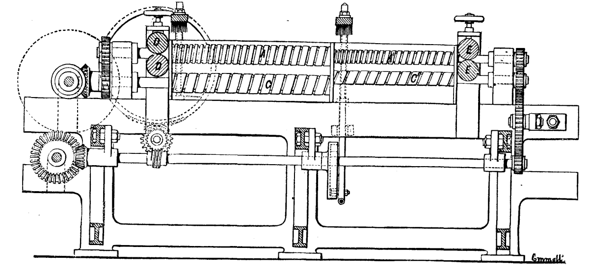
FIG. 2.—"SENSIM" SCREW GILL—SECTIONAL ELEVATION.
The speeds are so adjusted that the fibers are delivered to the first set of gills at a speed approximately equal to the speed at which these start their traverse. The gills in the second set begin their journey at a pace which slightly exceeds that at which those of the first finish their traverse. These paces are of course regulated by the class and nature of the fibers under operation. The delivery rollers, E, take off the fibers at a rate slightly exceeding that of the gills delivering it to them.

FIG. 3.—"SENSIM" SCREW GILL—PLAN.
In the ordinary gill box, the feed and delivery rollers are fluted, in order the better to retain in the first instance their grip upon the wool passing through, and in the second to enable them to overcome any resistance that might be offered to drawing the material. It thus often happens in this class of machines that a large percentage of the fibers are broken, and thus much waste is made. The substitution of plain rollers in both these positions obviates most of this mischief, while in combination with the other parts of the arrangement it is almost precluded altogether.
It will be obvious from what we have said that the special features of this machine, which may be summarized as, first, the use of a screw thread of graduated pitch; second, an increased length of screw action and an additional number of fallers; and third, the use of light plain rollers in place of heavy fluted back and front rollers, enable the inventor to justly claim the acquisition of a number of advantages, which may be enumerated as follows:
The transformation of the gills from mere carriers into constant workers during the whole of their outward traverse, by which the work is done much more efficiently, more gently, and in greater quantity than by the old system with uniformly pitched screws. A great improvement in the quality of the work, resulting from the breakage of fiber being, if not entirely obviated, nearly. An increased yield and better quality of top, owing to the absence of broken fiber, and consequent diminution of noil and waste. The better working of cotted wools, which can be brought to a proper condition with far more facility and with diminished risk of breaking pins than before. A saving in labor, space, and plant also results from the fact that the wool is as well opened and straightened for carding with a passage through a pair of improved boxes as it is in going through four of the ordinary ones, while the quantity will be as great. Owing to the first feature referred to, which distributes the strain over all the gills, a greater weight of wool can be put into them and a higher speed be worked. The space occupied and the attendance required is only about half that of boxes required to do the same amount of work on the old system. Taking the flutes out of the feed and delivery rollers, and greatly diminishing their weight, it is estimated will reduce by 90 per cent. the wear and tear of the leather aprons, and thus to that extent diminish a very heavy annual outlay incident to the system generally in vogue. A considerable saving of power for driving and of time and cost of repairs from the bending and breakage of pins also results. Shaw, Harrison & Co., makers, Bradford.—Textile Manufacturer.
Black wool dresses for renewing and checked goods, with the check not covered by the first operation, are operated upon as follows:
Preparation or mordant for eight black dresses for renewing the color.
2 oz. Chrome.
2  "  Argol or Tartar.
Or without argol or tartar, but I think their use is beneficial. Boil twenty minutes, lift, rinse through two waters.
To prepare dye boiler, put in 2 lb. logwood, boil twenty minutes. Clear the face same way as before described. Those with cotton and made-up dresses sewn with cotton same operation as before mentioned, using half the quantity of stuffs, and working cold throughout. Since the introduction of aniline black, some dyers use it in place of logwood both for wool and cotton. It answers very well for dippers, substituting 2 oz. aniline black for every pound logwood required. In dyeing light bottoms it is more expensive than logwood, even though the liquor be kept up, and, in my opinion, not so clear and black.
Silk and wool dresses, poplins, and woolen dresses trimmed with silk, etc., for black.—Before the dyeing operations, steep the goods in hand-heat soda water, rinse through two warm waters. Discharge blues, mauves, etc., with diluted aquafortis (nitric acid). A skilled dyer can perform this operation without the least injury to the goods. This liquor is kept in stoneware, or a vessel made of caoutchouc composition, or a large stone hollowed out of five slabs of stone, forming the bottom and four sides, braced together, and luted with caoutchouc, forming a water-tight vessel. The latter is the most convenient vessel, as it can be repaired. The others when once rent are past repair. The steam is introduced by means of a caoutchouc pipe, and when brought to the boil the pipe is removed. After the colors are discharged, rinse through three warm waters. They are then ready to receive the mordant and the dye.
Note.—The aquafortis vessel to be outside the dye-house, or, if inside, to be provided with a funnel to carry away the nitrous fumes, as it is dangerous to other colors.
Preparation or mordant for eight dresses, silk and wool mixed, for black.
4 lb. Copperas.
½  "  Bluestone.
½  "  Tartar.
Bring to the boil, dissolve the copperas, etc., shut off steam, enter the goods, handle gently (or else they will be faced, i.e., look gray on face when dyed) for one hour, lift, air, rinse through three warm waters.
To prepare dye boiler, bring to boil, put in 8 lb. logwood (previously boiled), 1 lb. black or brown oil soap, shut off steam, enter goods, gently handle for half an hour, add another pound of soap (have the soap dissolved ready), and keep moving for another half hour, lift, finish in hand-heat soap. If very heavy, run through lukewarm water slightly acidulated with vitriol, rinse, hydro-extract, and hang in stove. Another method to clear them: Make up three lukewarm waters, in first put some bleaching liquor, in second a little vitriol, handle these two, and rinse through the third, hydro-extract, and hang in stove.
Note.—This is the method employed generally in small dye-works for all dresses for black; their lots are so small. This preparation can be kept up, if care is taken that none of the sediment of the copperas (oxide of iron) is introduced when charging, as the oxide of iron creates stains. This also happens when the water used contains iron in quantity or impure copperas. The remedy is to substitute half a gill of vitriol in place of tartar.
Silk, wool, and cotton mixed dresses, for black.—Dye the silk and wool as before described, and also the cotton in the manner previously mentioned.
Another method to dye the mixed silk and wool and cotton dresses black, four dresses.—Bring boiler to the boil, put in 3 or 4 oz. aniline black, either the deep black or the blue black or a mixture of the two, add ¼ gill hydrochloric acid or sulphuric acid, or 3 oz. oxalic acid, shut off steam, enter, and handle for half an hour, lift, rinse through water, dye the cotton in the manner previously described.—Dyer.
The points to which I specially called your attention in the first lecture, and which it is necessary to recapitulate to-day, are these: (1) That coal is distilled, or burned partly into gas, before it can be burned. (2) That the gas, so given off, if mixed with carbonic acid, cannot be expected to burn properly or completely. (3) That to burn the gas, a sufficient supply of air must be introduced at a temperature not low enough to cool the gases below their igniting point. (4) That in stoking a fire, a small amount should be added at a time because of the heat required to warm and distill the fresh coal. (5) That fresh coal should be put in front of or at the bottom of a fire, so that the gas may be thoroughly heated by the incandescent mass above and thus, if there be sufficient air, have a chance of burning. A fire may be inverted, so that the draught proceeds through it downward. This is the arrangement in several stoves, and in them, of course, fresh coal is put at the top.
Two simple principles are at the root of all fire management: (1) Coal gas must be at a certain temperature before it can burn; and (2) it must have a sufficient supply of air. Very simple, very obvious, but also extremely important, and frequently altogether ignored. In a common open fire they are both ignored. Coal is put on the top of a glowing mass of charcoal, and the gas distilled off is for a longtime much too cold for ignition, and when it does catch fire it is too mixed with carbonic acid to burn completely or steadily. In order to satisfy the first condition better, and keep the gases at a higher temperature, Dr. Pridgin Teale arranges a sloping fire-clay slab above his fire. On this the gases play, and its temperature helps them to ignite. It also acts as a radiator, and is said to be very efficient.
In a close stove and in many furnaces the second condition is violated; there is an insufficient supply of air; fresh coal is put on, and the feeding doors are shut. Gas is distilled off, but where is it to get any air from? How on earth can it be expected to burn? Whether it be expected or not, it certainly does not burn, and such a stove is nothing else than a gas works, making crude gas, and wasting it—it is a soot and smoke factory.
Most slow combustion stoves are apt to err in this way; you make the combustion slow by cutting off air, and you run the risk of stopping the combustion altogether. When you wish a stove to burn better, it is customary to open a trap door below the fuel; this makes the red hot mass glow more vigorously, but the oxygen will soon become CO2, and be unable to burn the gas.
The right way to check the ardor of a stove is not to shut off the air supply and make it distill its gases unconsumed, but to admit so much air above the fire that the draught is checked by the chimney ceasing to draw so fiercely. You at the same time secure better ventilation; and if the fire becomes visible to the room so much the better and more cheerful. But if you open up the top of a stove like this, it becomes, to all intents and purposes, an open fire. Quite so, and in many respects, therefore, an open fire is an improvement on a close stove. An open fire has faults, and it certainly wastes heat up the chimney. A close stove may have more faults—it wastes less heat, but it is liable to waste gas up the chimney—not necessarily visible or smoky gas; it may waste it from coke or anthracite, as CO.
You now easily perceive the principles on which so-called smoke consumers are based. They are all special arrangements or appendages to a furnace for permitting complete combustion by satisfying the two conditions which had been violated in its original construction. But there is this difficulty about the air supply to a furnace: the needful amount is variable if the stoking be intermittent, and if you let in more than the needful amount, you are unnecessarily wasting heat and cooling the boiler, or whatever it is, by a draught of cold air.
Every time a fresh shovelful is thrown on, a great production of gas occurs, and if it is to flame it must have a correspondingly great supply of air. After a time, when the mass has become red hot, it can get nearly enough air through the bars. But at first the evolution of gas actually checks the draught. But remember that although no smoke is visible from a glowing mass, it by no means follows that its combustion is perfect. On an open fire it probably is perfect, but not necessarily in a close stove or furnace. If you diminish the supply of air much (as by clogging your furnace bars and keeping the doors shut), you will be merely distilling carbonic oxide up the chimney—a poisonous gas, of which probably a considerable quantity is frequently given off from close stoves.
Now let us look at some smoke consumers. The diagrams show those of Chubb, Growthorpe, Ireland and Lowndes, and of Gregory. You see that they all admit air at the "bridge" or back of the fire, and that this air is warmed either by passing under or round the furnace, or in one case through hollow fire bars. The regulation of the air supply is effected by hand, and it is clear that some of these arrangements are liable to admit an unnecessary supply of air, while others scarcely admit enough, especially when fresh coal is put on. This is the difficulty with all these arrangements when used with ordinary hand—i.e., intermittent—stoking. Two plans are open to us to overcome the difficulty. Either the stoking and the air supply must both be regular and continuous, or the air supply be made intermittent to suit the stoking. The first method is carried out in any of the many forms of mechanical stoker, of which this of Sinclair's is an admirable specimen. Fresh fuel is perpetually being pushed on in front, and by alternate movement of the fire bars the fire is kept in perpetual motion till the ashes drop out at the back. To such an arrangement as this a steady air supply can be adjusted, and if the boiler demand is constant there is no need for smoke, and an inferior fuel may be used. The other plan is to vary the air supply to suit the stoking. This is effected by Prideaux automatic furnace doors, which have louvers to remain open for a certain time after the doors are shut, and so to admit extra air immediately after coal has been put on, the supply gradually decreasing as distillation ceases. The worst of air admitted through chinks in the doors, or through partly open doors, is that it is admitted cold, and scarcely gets thoroughly warm before it is among the stuff it has to burn. Still this is not a fatal objection, though a hot blast would be better. Nothing can be worse than shoveling on a quantity of coal and shutting it up completely. Every condition of combustion is thus violated, and the intended furnace is a mere gas retort.
Gas Producers.—Suppose the conditions of combustion are purposely violated; we at once have a gas producer. That is all gas producers are, extra bad stoves or furnaces, not always much worse than things which pretend to serve for combustion. Consider how ordinary gas is made. There is a red-hot retort or cylinder plunged in a furnace. Into this tube you shovel a quantity of coal, which flames vigorously as long as the door is open, but when it is full you shut the door, thus cutting off the supply of air and extinguishing the flame. Gas is now simply distilled, and passes along pipes to be purified and stored. You perceive at once that the difference between a gas retort and an ordinary furnace with closed doors and half choked fire bars is not very great. Consumption of smoke! It is not smoke consumers you really want, it is fuel consumers. You distill your fuel instead of burning it, in fully one-half, might I not say nine-tenths, of existing furnaces and close stoves. But in an ordinary gas retort the heat required to distill the gas is furnished by an outside fire; this is only necessary when you require lighting gas, with no admixture of carbonic acid and as little carbonic oxide as possible. If you wish for heating gas, you need no outside fire; a small fire at the bottom of a mass of coal will serve to distill it, and you will have most of the carbon also converted into gas. Here, for instance, is Siemens' gas producer. The mass of coal is burning at the bottom, with a very limited supply of air. The carbonic acid formed rises over the glowing coke, and takes up another atom of carbon to form the combustible gas carbonic oxide. This and the hot nitrogen passing over and through the coal above distill away its volatile constituents, and the whole mass of gas leaves by the exit pipe. Some art is needed in adjusting the path of the gases distilled from the fresh coal with reference to the hot mass below. If they pass too readily, and at too low a temperature, to the exit pipe, this is apt to get choked with tar and dense hydrocarbons. If it is carried down near or through the hot fuel below, the hydrocarbons are decomposed over much, and the quality of the gas becomes poor. Moreover, it is not possible to make the gases pass freely through a mass of hot coke; it is apt to get clogged. The best plan is to make the hydrocarbon gas pass over and near a red-hot surface, so as to have its heaviest hydrocarbons decomposed, but so as to leave all those which are able to pass away as gas uninjured, for it is to the presence of these that the gas will owe its richness as a combustible material, especially when radiant heat is made use of.
The only inert and useless gas in an arrangement like this is the nitrogen of the air, which being in large quantities does act as a serious diluent. To diminish the proportion of nitrogen, steam is often injected as well as air. The glowing coke can decompose the steam, forming carbonic oxide and hydrogen, both combustible. But of course no extra energy can be gained by the use of steam in this way; all the energy must come from the coke, the steam being already a perfectly burned product; the use of steam is merely to serve as a vehicle for converting the carbon into a convenient gaseous equivalent. Moreover, steam injected into coke cannot keep up the combustion; it would soon put the fire out unless air is introduced too. Some air is necessary to keep up the combustion, and therefore some nitrogen is unavoidable. But some steam is advisable in every gas producer, unless pure oxygen could be used instead of air; or unless some substance like quicklime, which holds its oxygen with less vigor than carbon does, were mixed with the coke and used to maintain the heat necessary for distillation. A well known gas producer for small scale use is Dowson's. Steam is superheated in a coil of pipe, and blown through glowing anthracite along with air. The gas which comes off consists of 20 per cent. hydrogen, 30 per cent. carbonic oxide, 3 per cent. carbonic acid, and 47 per cent. nitrogen. It is a weak gas, but it serves for gas engines, and is used, I believe, by Thompson, of Leeds, for firing glass and pottery in a gas kiln. It is said to cost 4d. per 1,000 ft., and to be half as good as coal gas.
For furnace work, where gas is needed in large quantities, it must be made on the spot. And what I want to insist upon is this, that all well-regulated furnaces are gas retorts and combustion chambers combined. You may talk of burning coal, but you can't do it; you must distill it first, and you may either waste the gas so formed or you may burn it properly. The thing is to let in not too much air, but just air enough. Look, for instance, at Minton's oven for firing pottery. Round the central chamber are the coal hoppers, and from each of these gas is distilled, passes into the central chamber, where the ware is stacked, and meeting with an adjusted supply of air as it rises, it burns in a large flame, which extends through the whole space and swathes the material to be heated. It makes its exit by a central hole in the floor, and thence rises by flues to a common opening above. When these ovens are in thorough action, nothing visible escapes. The smoke from ordinary potters' ovens is in Staffordshire a familiar nuisance. In the Siemens gas producer and furnace, of which Mr. Frederick Siemens has been good enough to lend me this diagram, the gas is not made so closely on the spot, the gas retort and furnace being separated by a hundred yards or so in order to give the required propelling force. But the principle is the same; the coal is first distilled, then burnt. But to get high temperature, the air supply to the furnace must be heated, and there must be no excess. If this is carried on by means of otherwise waste heat we have the regenerative principle, so admirably applied by the Brothers Siemens, where the waste heat of the products of combustion is used to heat the incoming air and gas supply. The reversing arrangement by which the temperature of such a furnace can be gradually worked up from ordinary flame temperature to something near the dissociation point of gases, far above the melting point of steel, is well known, and has already been described in this place. Mr. Siemens has lent me this beautiful model of the most recent form of his furnace, showing its application to steel making and to glass working.
The most remarkable and, at first sight, astounding thing about this furnace is, however, that it works solely by radiation. The flames do not touch the material to be heated; they burn above it, and radiate their heat down to it. This I regard as one of the most important discoveries in the whole subject, viz., that to get the highest temperature and greatest economy out of the combustion of coal, one must work directly by radiant heat only, all other heat being utilized indirectly to warm the air and gas supply, and thus to raise the flame to an intensely high temperature.
It is easy to show the effect of supplying a common gas flame with warm air by holding it over a cylinder packed with wire gauze which has been made red hot. A common burner held over such a hot air shaft burns far more brightly and whitely. There is no question but that this is the plan to get good illumination out of gas combustion; and many regenerative burners are now in the market, all depending on this principle, and utilizing the waste heat to make a high temperature flame. But although it is evidently the right way to get light, it was by no means evidently the right way to get heat. Yet so it turns out, not by warming solid objects or by dull warm surfaces, but by the brilliant radiation of the hottest flame that can be procured, will rooms be warmed in the future. And if one wants to boil a kettle, it will be done, not by putting it into a non-luminous flame, and so interfering with the combustion, but by holding it near to a freely burning regenerated flame, and using the radiation only. Making toast is the symbol of all the heating of the future, provided we regard Mr. Siemens' view as well established.
The ideas are founded on something like the following considerations: Flame cannot touch a cold surface, i.e., one below the temperature of combustion, because by the contact it would be put out. Hence, between a flame and the surface to be heated by it there always intervenes a comparatively cool space, across which heat must pass by radiation. It is by radiation ultimately, therefore, that all bodies get heated. This being so, it is well to increase the radiating power of flame as much as possible. Now, radiating power depends on two things: the presence of solid matter in the flame in a fine state of subdivision, and the temperature to which it is heated. Solid matter is most easily provided by burning a gas rich in dense hydrocarbons, not a poor and non-luminous gas. To mix the gas with air so as to destroy and burn up these hydrocarbons seems therefore to be a retrograde step, useful undoubtedly in certain cases, as in the Bunsen flame of the laboratory, but not the ideal method of combustion. The ideal method looks to the use of a very rich gas, and the burning of it with a maximum of luminosity. The hot products of combustion must give up their heat by contact. It is for them that cross tubes in boilers are useful. They have no combustion to be interfered with by cold contacts. The flame only should be free.
The second condition of radiation was high temperature. What limits the temperature of a flame? Dissociation or splitting up of a compound by heat. So soon as the temperature reaches the dissociation point at which the compound can no longer exist, combustion ceases. Anything short of this may theoretically be obtained.
But Mr. Siemens believes, and adduces some evidence to prove, that the dissociation point is not a constant and definite temperature for a given compound; it depends entirely upon whether solid or foreign surfaces are present or not. These it is which appear to be an efficient cause of dissociation, and which, therefore, limit the temperature of flame. In the absence of all solid contact, Mr. Siemens believes that dissociation, if it occur at all, occurs at an enormously higher temperature, and that the temperature of free flame can be raised to almost any extent. Whether this be so or not, his radiating flames are most successful, and the fact that large quantities of steel are now melted by mere flame radiation speaks well for the correctness of the theory upon which his practice has been based.
Use of Small Coal.—Meanwhile, we may just consider how we ought to deal with solid fuel, whether for the purpose of making gas from it or for burning it in situ. The question arises, In what form ought solid fuel to be—ought it to be in lumps or in powder? Universal practice says lumps, but some theoretical considerations would have suggested powder. Remember, combustion is a chemical action, and when a chemist wishes to act on a solid easily, he always pulverizes it as a first step.
Is it not possible that compacting small coal into lumps is a wrong operation, and that we ought rather to think of breaking big coal down into slack? The idea was suggested to me by Sir W. Thomson in a chance conversation, and it struck me at once as a brilliant one. The amount of coal wasted by being in the form of slack is very great. Thousands of tons are never raised from the pits because the price is too low to pay for the raising—in some places it is only 1s. 6d. a ton. Mr. McMillan calculates that 130,000 tons of breeze, or powdered coke, is produced every year by the Gas Light and Coke Company alone, and its price is 3s. a ton at the works, or 5s. delivered.
The low price and refuse character of small coal is, of course, owing to the fact that no ordinary furnace can burn it. But picture to yourself a blast of hot air into which powdered coal is sifted from above like ground coffee, or like chaff in a thrashing mill, and see how rapidly and completely it might burn. Fine dust in a flour mill is so combustible as to be explosive and dangerous, and Mr. Galloway has shown that many colliery explosions are due not to the presence of gas so much as the presence of fine coal-dust suspended in the air. If only fine enough, then such dust is eminently combustible, and a blast containing it might become a veritable sheet of flame. (Blow lycopodium through a flame.) Feed the coal into a sort of coffee-mill, there let it be ground and carried forward by a blast to the furnace where it is to be burned. If the thing would work at all, almost any kind of refuse fuel could be burned—sawdust, tan, cinder heaps, organic rubbish of all kinds. The only condition is that it be fine enough.
Attempts in this direction have been made by Mr. T.R. Crampton, by Messrs. Whelpley and Storer, and by Mr. G.K. Stephenson; but a difficulty has presented itself which seems at present to be insuperable, that the slag fluxes the walls of the furnace, and at that high temperature destroys them. If it be feasible to keep the flame out of contact with solid surfaces, however, perhaps even this difficulty can be overcome.
Some success in blast burning of dust fuel has been attained in the more commonplace method of the blacksmith's forge, and a boiler furnace is arranged at Messrs. Donkin's works at Bermondsey on this principle. A pressure of about half an inch of water is produced by a fan and used to drive air through the bars into a chimney draw of another half-inch. The fire bars are protected from the high temperatures by having blades which dip into water, and so keep fairly cool. A totally different method of burning dust fuel by smouldering is attained in M. Ferret's low temperature furnace by exposing the fuel in a series of broad, shallow trays to a gentle draught of air. The fuel is fed into the top of such a furnace, and either by raking or by shaking it descends occasionally, stage by stage, till it arrives at the bottom, where it is utterly inorganic and mere refuse. A beautiful earthworm economy of the last dregs of combustible matter in any kind of refuse can thus be attained. Such methods of combustion as this, though valuable, are plainly of limited application; but for the great bulk of fuel consumption some gas-making process must be looked to. No crude combustion of solid fuel can give ultimate perfection.
Coal tar products, though not so expensive as they were some time back, are still too valuable entirely to waste, and the importance of exceedingly cheap and fertilizing manure in the reclamation of waste lands and the improvement of soil is a question likely to become of most supreme importance in this overcrowded island. Indeed, if we are to believe the social philosophers, the naturally fertile lands of the earth may before long become insufficient for the needs of the human race; and posterity may then be largely dependent for their daily bread upon the fertilizing essences of the stored-up plants of the carboniferous epoch, just as we are largely dependent on the stored-up sunlight of that period for our light, our warmth, and our power. They will not then burn crude coal, therefore. They will carefully distill it—extract its valuable juices—and will supply for combustion only its carbureted hydrogen and its carbon in some gaseous or finely divided form.
Gaseous fuel is more manageable in every way than solid fuel, and is far more easily and reliably conveyed from place to place. Dr. Siemens, you remember, expected that coal would not even be raised, but turned into gas in the pits, to rise by its own buoyancy to be burnt on the surface wherever wanted. And not only will the useful products be first removed and saved, its sulphur will be removed too; not because it is valuable, but because its product of combustion is a poisonous nuisance. Depend upon it, the cities of the future will not allow people to turn sulphurous acid wholesale into the air, there to oxidize and become oil of vitriol. Even if it entails a slight strain upon the purse they will, I hope, be wise enough to prefer it to the more serious strain upon their lungs. We forbid sulphur as much as possible in our lighting gas, because we find it is deleterious in our rooms. But what is London but one huge room packed with over four millions of inhabitants? The air of a city is limited, fearfully limited, and we allow all this horrible stuff to be belched out of hundreds of thousands of chimneys all day long.
Get up and see London at four or five in the morning, and compare it with four or five in the afternoon; the contrast is painful. A city might be delightful, but you make it loathsome; not only by smoke, indeed, but still greatly by smoke. When no one is about, then the air is almost pure; have it well fouled before you rise to enjoy it. Where no one lives, the breeze of heaven still blows; where human life is thickest, there it is not fit to live. Is it not an anomaly, is it not farcical? What term is strong enough to stigmatize such suicidal folly? But we will not be in earnest, and our rulers will talk, and our lives will go on and go out, and next century will be soon upon us, and here is a reform gigantic, ready to our hands, easy to accomplish, really easy to accomplish if the right heads and vigorous means were devoted to it. Surely something will be done.
The following references may be found useful in seeking for more detailed information: Report of the Smoke Abatement Committee for 1882, by Chandler Roberts and D.K. Clark. "How to Use Gas," by F.T. Bond; Sanitary Association, Gloucester. "Recovery of Volatile Constituents of Coal," by T.B. Lightfoot; Journal Society of Arts, May, 1883. "Manufacture of Gas from Oil," by H.E. Armstrong; Journal Society of Chemical Industry, September, 1884. "Coking Coal," by H.E. Armstrong; Iron and Steel Institute, 1885. "Modified Siemens Producer," by John Head; Iron and Steel Institute, 1885. "Utilization of Dust Fuel," by W.G. McMillan; Journal Society of Arts, April. 1886. "Gas Producers," by Rowan; Proc. Inst. C.E., January, 1886. "Regenerative Furnaces with Radiation," and "On Producers," by F. Siemens; Journal Soc. Chem. Industry, July, 1885, and November, 1885. "Fireplace Construction," by Pridgin Teale; the Builder, February, 1886. "On Dissociation Temperatures," by Frederick Siemens; Royal Institution, May 7, 1886.
[1]Near Colorados, in the Argentine Republic, a large bed of superior coal has been opened, and to the west of the Province of Buenos Ayres extensive borax deposits have been discovered.
The accompanying engraving illustrates a remarkable invention. For ages, screw conveyers for corn and meal have been employed, and in spite of the power consumed and the rubbing of the material conveyed, they have remained, with little exception, unimproved and without a rival. Now we have a new conveyer, which, says The Engineer, in its simplicity excels anything brought out for many years, and, until it is seen at work, makes a heavier demand upon one's credulity than is often made by new mechanical inventions. As will be seen from the engravings, the new conveyer consists simply of a spiral of round steel rod mounted upon a quickly revolving spindle by means of suitable clamps and arms. The spiral as made for England is of 5/8 in. steel rod, because English people would not be inclined to try what is really sufficient in most cases, namely, a mere wire. The working of this spiral as a conveyer is simply magical. A 6 in. spiral delivers 800 bushels per hour at 100 revolutions per minute, and more in proportion at higher speeds. A little 4 in. spiral delivers 200 bushels per hour at 100 revolutions per minute. It seems to act as a mere persuader. The spiral moves a small quantity, and sets the whole contents of the trough in motion. In fact, it embodies the great essentials of success, namely, simplicity, great capacity for work, and cheapness. It is the invention of Mr. J. Little, and is made by the Anti-friction Conveyer Company, of 59 Mark Lane, London.

THE ANTI-FRICTION CONVEYER WITH CASING OR TROUGH—END VIEW WITH HANGER.
Since the days of Archimedes, who is credited with being the inventor of the screw, there has not been any improvement in the principle of the worm conveyer. There have been several patents taken out for improved methods of manufacturing the old-fashioned continuous and paddle-blade worms, but Mr. Little's patent is the first for an entirely new kind of conveyer.
Torches consist of a bundle of loosely twisted threads which has been immersed in a mixture formed of two parts, by weight, of beeswax, eight of resin, and one of tallow. In warm, dry weather, these torches when lighted last for two hours when at rest, and for an hour and a quarter on a march. A good light is obtained by spacing them 20 or 30 yards apart.
Another style of torch consists of a cardboard cylinder fitted with a composition consisting of 100 parts of saltpeter, 60 of sulphur, 8 of priming powder, and 30 of pulverized glass, the whole sifted and well mixed. This torch, which burns for a quarter of an hour, illuminates a space within a radius of 180 or 200 yards very well.
The tourteau goudronné (lit. "tarred coke") is merely a ring formed of old lunt or of cords well beaten with a mallet (Fig. 10). This ring is first impregnated with a composition formed of 20 parts of black pitch and 1 of tallow, and then with another one formed of equal parts of black pitch and resin. One of these torches will burn for an hour in calm weather, and half an hour in the wind. Rain does not affect the burning of it. These rings are usually arranged in pairs on brackets with two branches and an upper circle, the whole of iron, and these brackets are spaced a hundred yards apart.

FIGS. 9 TO 16.—VARIOUS PYROTECHNIC DEVICES.

FIGS. 17.—ILLUMINATING ROCKET.
A tarred fascine consists of a small fagot of dry wood, 20 inches in length by 4 in diameter, covered with the same composition as the preceding (Fig. 11). Fascines thus prepared burn for about half an hour. They are placed upright in supports, and these latter are located at intervals of twenty yards.
The Lamarre compositions are all formed of a combustible substance, such as boiled oil,2 of a substance that burns, such as chlorate of potash, and of various coloring salts.
The white composition used for charging fire balls and 1½ inch flambeaux is formed of 500 parts of powdered chlorate of potash, 1,500 of nitrate of baryta, 120 of light wood charcoal, and 250 of boiled oil. Another white composition, used for charging ¾ inch flambeaux, consists of 1,000 parts of chlorate of potash, 1,000 of nitrate of baryta, and 175 of boiled oil.
The red composition used for making red flambeaux and percussion signals consists of 1,800 parts of chlorate of potash, 300 of oxalate of strontia, 300 of carbonate of strontia, 48 of whitewood charcoal, 240 of boiled oil, 6 of oil, and 14 of gum lac.
A red or white Lamarre flambeau consists of a sheet rubber tube filled with one of the above-named compositions. The lower extremity of this tube is closed with a cork. When the charging has been effected, the flambeau is primed by inserting a quickmatch in the composition. This is simply lighted with a match or a live coal. The composition of the Lamarre quickmatch will be given hereafter.
A Lamarre flambeau 1½ inch in diameter and 3 inches in length will burn for about thirty-five minutes. One of the same length, and ¾ inch in diameter, lasts but a quarter of an hour.
A fire ball consists of an open work sack internally strengthened with a sheet iron shell, and fitted with the Lamarre white composition. After the charging has been done, the sphere is wound with string, which is made to adhere by means of tar, and canvas is then wrapped around the whole. Projectiles of this kind, which have diameters of 6, 8, 11, and 13 inches, are shot from mortars.
The illuminating grenade (Fig. 13) consists of a sphere of vulcanized rubber, two inches in diameter, charged with the Lamarre white composition. The sphere contains an aperture to allow of the insertion of a fuse. The priming is effected by means of a tin tube filled with a composition consisting of three parts of priming powder, two of sulphur, and one of saltpeter. These grenades are thrown either by hand or with a sling, and they may likewise be shot from mortars. Each of these projectiles illuminates a circle thirty feet in diameter for a space of time that varies, according to the wind, from sixty to eighty seconds.
The percussion signal (Fig. 14) consists of a cylinder of zinc, one inch in diameter and one and a quarter inch in length, filled with Lamarre red composition. It is provided with a wooden handle, and the fuse consists of a capsule which is exploded by striking it against some rough object. This signal burns for nearly a minute.
Belgian illuminating balls and cylinders are canvas bags filled with certain compositions. The cylinders, five inches in diameter and seven in length, are charged with a mixture of six parts of sulphur, two of priming powder, one of antimony, and two of beeswax cut up into thin slices. They are primed with a quickmatch. The balls, one and a half inch in diameter, are charged with a composition consisting of twelve parts of saltpeter, eight of sulphur, four of priming powder, two of sawdust, two of beeswax, and two of tallow. They are thrown by hand. They burn for six minutes.
Illuminating kegs (Fig. 15) consist of powder kegs filled with shavings covered with pitch. An aperture two or three inches in diameter is made in each head, and then a large number of holes, half an inch in diameter, and arranged quincuncially, are bored in the staves and heads. All these apertures are filled with port-fires.
The illuminating rocket (Fig. 17) consists of a sheet iron cartridge, a, containing a composition designed to give it motion, of a cylinder, b, of sheet iron, capped with a cone of the same material and containing illuminating stars of Lamarre composition and an explosive for expelling them, and, finally, of a directing stick, c. Priming is effected by means of a bunch of quickmatches inclosed in a cardboard tube placed in contact with the propelling composition. This latter is the same as that used in signal rockets. As in the case of the latter, a space is left in the axis of the cartridges. These rockets are fired from a trough placed at an inclination of fifty or sixty degrees. Those of three inches illuminate the earth for a distance of 900 yards. They may be used to advantage in the operation of signaling.
A parachute fire is a device designed to be ejected from a pot at the end of the rocket's travel, and to emit a bright light during its slow descent. It consists of a small cylindrical cardboard box (Fig. 16) filled with common star paste or Lamarre stars, and attached to a parachute, e, by means of a small brass chain, d.
To make this parachute, we cut a circle ten feet in diameter out of a piece of calico, and divide its circumference into ten or twelve equal parts. At each point of division we attach a piece of fine hempen cord about three feet in length, and connect these cords with each other, as well as with the suspension chain, by ligatures that are protected against the fire by means of balls of sized paper.
In rockets designed to receive these parachutes, a small cavity is reserved at the extremity of the cartridge for the reception of 225 grains of powder. To fill the pot, the chain, d, is rolled spirally around the box, c, and the latter is covered with the parachute, e, which has been folded in plaits, and then folded lengthwise alternately in one direction and the other.
The parachute port-fire consists of a cardboard tube of from quarter to half an inch in diameter, and from four to five inches in length, closed at one extremity and filled with star paste. This is connected by a brass wire with a cotton parachute eight inches in diameter. A rocket pot is capable of holding twenty of these port-fires.
Parachute fires and port-fires are used to advantage in the operation of signaling.—La Nature.
[1]To avoid the long and time-consuming laying out of a boat by ordinates and abscissas, I have constructed a handy apparatus, by which it is possible without much trouble to obtain the sections of a vessel graphically and sufficiently accurate. The description of its construction is given with reference to the accompanying cut. A is a wooden rod of rectangular section, to which are adapted two brackets, a1 a2, lined with India rubber or leather; a1 is fixed to the wood, a2 is of metal, and, like the movable block of a slide gauge, moves along A. In the same plane is a second rod, perpendicular to A, and attached thereto, which is perforated by a number of holes. A revolving pin, C, is adapted to pass through these holes, to which a socket, D, is pivoted, C acting as its axis. To prevent this pin from falling out, it is secured by a nut behind the rod. Through the socket, D, runs a rod, E, which carries the guide point, s1, and pencil, s2. Over s1 a rubber band is stretched, to prevent injury to the varnish of the boat. Back of and to A and B a drawing board is attached, over which a sheet of paper is stretched.

THE FRAME TRACER.
The method of obtaining a section line is as follows: The rod, A, is placed across the gunwale and perpendicular to the axis of the boat, and its anterior vertical face is adjusted to each frame of the boat which it is desired to reproduce. By means of the brackets, a1 and a2, A is fixed in place. The bolt, C, is now placed in the perforations already alluded to, which are recognized as most available for producing the constructional diagram. At the same time the position of the pencil point, s2, must be chosen for obtaining the best results.
Next the operator moves along the side of the boat the sharpened end, s1, of the rod, E, and thus for the curve from keel to gunwale, s2 describes a construction line. It is at once evident that a2, for example, corresponds to the point, a1. The apparatus is now removed and placed on the working floor. If, reversing things, the point, s1, is carried around the construction curve, the point, s2, will inscribe the desired section in its natural dimensions. This operation is best conducted after one has chosen and described all the construction curves of the boat. Next, the different section lines are determined, one by one, by the reversed method above described. The result is a half section of the boat; the other symmetrical half is easily obtained.
If the whole process is repeated for the other side of the boat, tracing paper being used instead of drawing paper, the boat may be tested for symmetry of building, a good control for the value of the ship. For measuring boats, as for clubs and regattas, for seamen, and often for the so-called Spranzen (copying) of English models, my apparatus, I doubt not, will be very useful.—Neuste Erfindungen und Erfahrungen.
The attention of gas engineers has been forcibly directed to the use of tar as a fuel for the firing of retorts, now that this once high-priced material is suffering, like everything else (but, perhaps, to a more marked extent), by what is called "depression in trade." In fact, it has in many places reached so low a commercial value that it is profitable to burn it as a fuel. Happily, this is not the case at Nottingham; and our interest in tar as a fuel is more experimental, in view of what may happen if a further fall in tar products sets in. I have abandoned the use of steam injection for our experimental tar fires in favor of another system. The steam injectors produce excellent heats, but are rather intermittent in their action, and the steam they require is a serious item, and not always available.

Tar being a pseudo liquid fuel, in arranging for its combustion one has to provide for the 20 to 25 per cent. of solid carbon which it contains, and which is deposited in the furnace as a kind of coke or breeze on the distillation of the volatile portions, which are much more easily consumed than the tar coke.
I have adopted is one that can be readily adapted to an ordinary coke furnace, and be as readily removed, leaving the furnace as before. The diagram conveys some idea of the method adopted. An iron frame, d, standing on legs on the floor just in front of the furnace door, carries three fire tiles on iron bearers. The top one, a, is not moved, and serves to shield the upper face of the tile, b, from the fierce heat radiated from the furnace, and also causes the air that rushes into the furnace between the tiles, a and b, to travel over the upper face of the tile, b, on which the tar flows, thereby keeping it cool, and preventing the tar from bursting into flame until it reaches the edge of the tile, b, over the whole edge of which it is made to run fairly well by a distributing arrangement. A rapid combustion takes place here, but some unconsumed tar falls on to the bed below. About one-third of the grate area is filled up by a fire tile, and on this the tar coke falls. The tile, c, is moved away from time to time, and the tar coke that accumulates in front of it is pushed back on to the fire bars, e, at the back of the furnace, to be there consumed. Air is thus admitted, by three narrow slot-like openings, to the front of the furnace between the tiles, a, b, and c, and under c and through the fire bars, e. The air openings below are about three times the area of the openings in the front of the furnace; but as the openings between the fire bars and the tiles are always more or less covered by tar coke, it is impossible to say what the effective openings are. This disposition answers admirably, and requires little attention. Three minutes per hour per fire seems to be the average, and the labor is of a very light kind, consisting of clearing the passages between the tiles, and occasionally pushing back the coke on to the fire bars. These latter are not interfered with, and will not require cleaning unless any bricks in the furnace have been melted, when a bed of slag will be found on them.
required for these fires is very small, and less than with coke firing. I find that 0.08 in. vacuum is sufficient with tar fires, and 0.25 in. for coke fires. The fires would require less attention with more draught and larger tar supply, as the apertures do not so easily close with a sharp draught, and the tar is better carried forward into the furnace. A regular feed of tar is required, and considerable difficulty seems to have been experienced in obtaining this. So long as we employed ordinary forms of taps or valves, so long (even with filtration) did we experience difficulties with the flow of viscous tar. But on the construction of valves specially designed for the regulation of its flow, the difficulty immediately disappeared, and there is no longer the slightest trouble on this account. The labor connected with the feeding of furnaces with coke and cleaning fires from clinker is of a very arduous and heavy nature. Eight coke fires are normally considered to be work for one man. A lad could work sixteen of these tar fires.
Considerable attention has been paid to the composition of the furnace gases from the tar fires. The slightest deficiency in the air supply, of course, results in the immediate production of smoke, so that the damper must be set to provide always a sufficient air supply. Under these circumstances of damper, the following analyses of combustion gases from tar fires have been obtained:
                  No Smoke.
                  CO₂.       O.           CO.
                  11.7      5.0      Not determined.
                  13.3      3.7           "
                  10.8      5.4           "
                  14.8      2.5           "
                  13.5      3.0           "
                  12.4      5.6           "
                  12.4      4.6           "
                  13.1      5.9           "
                  15.3      1.0           "
                  10.8      4.0           "
                  14.0      2.8           "
                 ______    ______
   Average        12.9      3.9
(11 analyses)    ______    ______
                  11.5    Not determined.
                  14.3          "
                  14.6          "
Damper adjusted so that a slight smoke was observable in the combustion gases.
                CO₂.        O.           CO.
                 17.30     None.    Not determined.
                 16.60      "            "
                 16.50     0.1           "
                 15.80     0.1           "
                 16.20     1.8          0.7
                _______   _____        _____
Average          16.48     0.4          0.7
—Gas Engineer.
The mercury pumps now in use, whether those of Geissler, Alvergniat, Toepler, or Sprengel, although possessed of considerable advantages, have also serious defects. For instance, Geissler's pump requires a considerable number of taps, that of Alvergniat and Toepler is very fragile in consequence of its complicated system of tubes connected together, and that of Sprengel is only suitable for certain purposes.
The new mercury pump constructed by Messrs. Greisser and Friedrichs, at Stutzerbach, is remarkable for simplicity of construction and for the ease with which it is manipulated, and also because it enables us to arrive at a perfect vacuum.
The characteristic of this pump is, according to La Lumiere Electrique, a tap of peculiar construction. It has two tubes placed obliquely in respect to its axis, which, when we turn this tap 90 or 180 degrees, are brought opposite one of the three openings in the body of the tap.
Thus the striæ that are formed between the hollowed-out parts of the tap do not affect its tightness; and, besides, the turns of the tap have for their principal positions 90 and 180 degrees, instead of 45 and 90 degrees, as in Geissler's pump.
The working of the apparatus, which only requires the manipulation of a single tap, is very simple. When the mercury is raised, the tap is turned in such a manner that the surplus of the liquid can pass into the enlarged appendage, a, placed above the tap, and communication is then cut off by turning the tap to 90 degrees.
The mercury reservoir having descended, the bulb empties itself, and then the tap is turned on again, in order to establish communication with the exhausting tube. The tap is then closed, the mercury ascends again, and this action keeps on repeating.
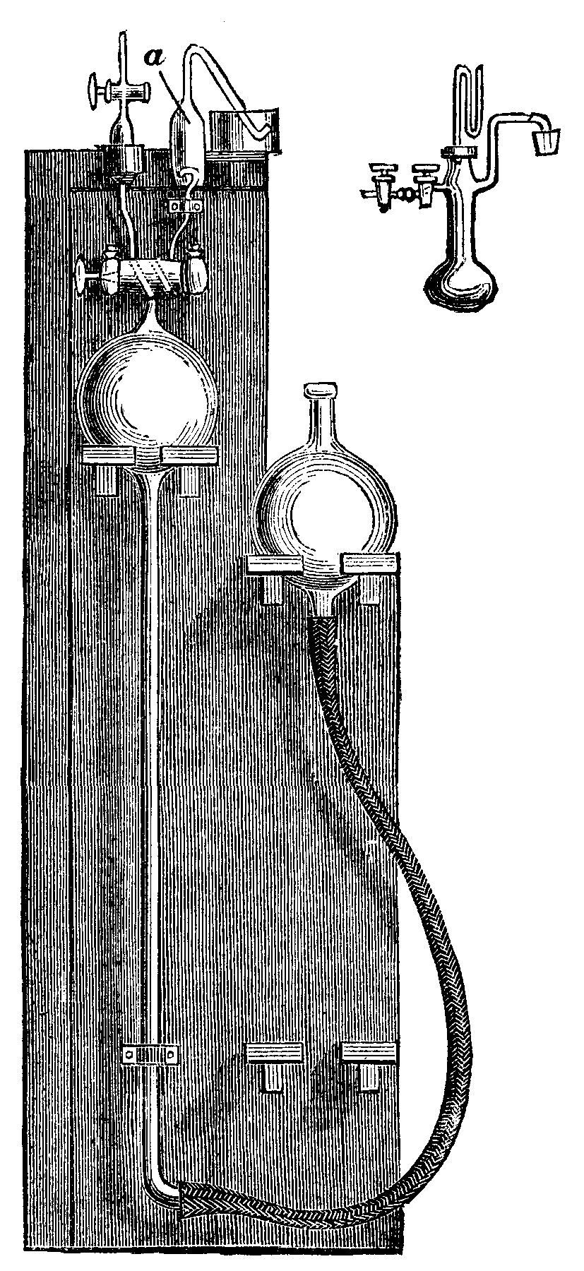
NO ELECTRICITY FROM THE CONDENSATION OF VAPOR.—It has been maintained by Palmieri and others that the condensation of vapor results in the production of an electrical charge. Herr S. Kalischer has renewed his investigations upon this point, and believes that he has proved that no electricity results from such condensation. Atmospheric vapor was condensed upon a vessel coated with tin foil, filled with ice, carefully insulated, and connected with a very sensitive electrometer. No evidence could be obtained of electricity.—Ann. der Physik und Chemie.
An interesting contribution was made by M. Mercadier in a recent number of the Comptes Rendus de l'Academie Francaise. On the ground of some novel and some already accepted experimental evidence, M. Mercadier holds that the mechanism by virtue of which the telephonic diaphragms execute their movements is analogous to, if not identical with, that by which solid bodies of any form, a wall for instance, transmit to one of their surfaces all the vibratory movements of any kind which are produced in the air in contact with the other surface. It is a phenomenon or resonance. Movements corresponding to particular sounds may be superposed in slender diaphragms, but this superposition must necessarily be disturbing under all but exceptional circumstances. In proof of this view, it is cited that diaphragms much too rigid, or charged with irregularly distributed masses over the surface, or pierced with holes, or otherwise evidently unfitted for the purpose, are available for transmission. They will likewise serve when feathers, wool, wood, metals, mica, and other substances to the thickness of four inches are placed between the diaphragm and the source of vibratory movement. The magnetic field does not alter these relations in any way. The real diaphragm may be removed altogether. It is sufficient to replace it by a few grains of iron filings thrown on the pole covered with a piece of pasteboard or paper. Such a telephone works distinctly although feebly; but any slender flexible disk, metallic or not, spread over across the opening of the cover of the instrument, with one or two tenths of a gramme (three grains) of iron filings, will yield results of increased and even ordinary intensity. This is the iron filing telephone, which is reversible; for a given magnetic field there is a certain weight of iron filings for maximum intensity. It appears thus that the advantage of the iron diaphragm over iron filings reduces itself to presenting in a certain volume a much more considerable number of magnetic molecules to the action of the field. The iron diaphragm increases the telephonic intensity, but it is by no means indispensable.
On the same principle that electro-dissolution is used for the estimation of combined carbon in steel, etc., I have lately varied the experiment by introducing, instead of steel, iron containing a certain percentage of boron, and, having connected the respective boride with the positive pole of a powerful battery, and to the negative a plate of platinum, using as a solvent dilute sulphuric acid, I observed, after the lapse of about twelve hours, the iron had entirely passed into solution, and a considerable amount of brownish precipitate had collected at the bottom of the vessel, intercepted by flakes of graphite and carbon; the precipitate, having been collected on a filter paper, washed, and dried, on examination proved to be amorphous boron, containing graphite and other impurities, which had become chemically introduced during the preparation of the boron compound. The boron was next introduced into a small clay crucible, and intensely heated in a current of hydrogen gas, for the purpose of rendering it more dense and destroying its pyrophoric properties, and was lastly introduced into a combustion tubing, heated to bright redness, and a stream of dry carbonic anhydride passed over it, in order to separate the carbon, finally pure boron being obtained.
In like manner silicon-eisen, containing 9 per cent. of silicon, was treated, but not giving so satisfactory a result. A small quantity only of silicon separates in the uncombined form, the greater quantity separating in the form of silica, SiO2, the amorphous silicon so obtained apparently being more prone to oxidation than the boron so obtained.
Ferrous sulphide was next similarly treated, and gave, after the lapse of a few hours, a copious blackish precipitation of sulphur, and possessing properties similar to the sulphur obtained by dissolving sulphides such as cupric sulphide in dilute nitric acid, in all other respects resembling common sulphur.
Phosphides of iron, zinc, etc., were next introduced, and gave, besides carbon and other impurities, a residue containing a large percentage of phosphorus, which differed from ordinary phosphorus with respect to its insolubility in carbon disulphide, and which resembled the reaction in the case with silicon-eisen rather than that of the boron compound, insomuch that a large quantity of the phosphorus had passed into solution.
A rod of impure copper, containing arsenic, iron, zinc, and other impurities, was next substituted, using hydrochloric acid as a solvent in place of sulphuric acid. In the course of a day the copper had entirely dissolved and precipitated itself on the negative electrode, the impurities remaining in solution. The copper, after having been washed, dried, and weighed, gave identical results with regard to percentage with a careful gravimetric estimation. I have lately used this method, and obtained excellent results with respect to the analysis of commercial copper, especially in the estimation of small quantities of arsenic, thus enabling the experimenter to perform his investigation on a much larger quantity than when precipitation is resorted to, at the same time avoiding the precipitated copper carrying down with it the arsenic. I have in this manner detected arsenic in commercial copper when all other methods have totally failed. I have also found the above method especially applicable with respect to the analysis of brass.
With respect to ammoniacal dissolution, which I will briefly mention, a rod composed of an alloy of copper and silver was experimented upon, the copper becoming entirely dissolved and precipitating itself on the platinum electrode, the whole of the silver remaining suspended to the positive electrode in an aborescent form. Arsenide of zinc was similarly treated, the arsenic becoming precipitated in like manner on the platinum electrode. Various other alloys, being experimented upon, gave similar results.
I may also, in the last instance, mention that I have found the above methods of electro-dissolution peculiarly adapted for the preparation of unstable compounds such as stannic nitrate, potassic ferrate, ferric acetate, which are decomposed on the application of heat, and in some instances have succeeded by the following means of crystallizing the resulting compound obtained.—Chem. News.
Dr. Leo's researches on sugar in urine are interesting, and tend to correct the commonly accepted views on the subject. Professor Scheibler, a chemist well known for his researches on sugar, has observed that the determination of the quantity of that substance contained in a liquid gives different results, according as it is done by Trommer's method or with the polariscope. As sugar nowadays is exclusively dealt with according to the degree of polarization, this fact is of enormous value in trade. Scheibler has isolated a substance that is more powerful in that respect than grape sugar. Dr. Leo's researches yield analogous results, though in a different field. He has examined a great quantity of diabetic urine after three different methods, namely, Trommer's (alkaline solution of copper); by fermentation; and with the polarization apparatus. In many cases the results agreed, while in others there was a considerable difference.
He succeeded in isolating a substance corresponding in its chemical composition to grape sugar, and also a carbo-hydrate differing considerably from grape sugar, and turning the plane of polarization to the left. The power of reduction of this newly discovered substance is to that of grape sugar as 1:2.48. Dr. Leo found this substance in three specimens of diabetic urine, but it was absent in normal urine, although a great amount was examined for that purpose. From this it may be concluded that the substance does not originate outside the organism, and that it is a pathological product. The theory of Dr. Jaques Meyer, of Carlsbad, that it may be connected with obesity, is negatived by the fact that of the three persons in whom this substance was found, only one was corpulent.

The problem of decomposing chloride of magnesium is one which has attracted the attention of technical chemists for many years. The solution of this problem would be of great importance to the alkali trade, and, consequently, to nearly every industry. The late Mr. Weldon made many experiments on this subject, but without any particular success. Of late a furnace has been patented in Germany, by A. Vogt, which is worked on a principle similar to that applied to salt cake furnaces; but with this difference, that in place of the pot it has a revolving drum, and instead of the roaster a furnace with a number of shelves. The heating gases are furnished by a producer, and pass from below upward over the shelves, S, then through the channel, C, into the drum, D, which contains the concentrated chloride of magnesium. When the latter has solidified, but before being to any extent decomposed, it is removed from the drum and placed on the top shelf of the furnace. It is then gradually removed one shelf lower as the decomposition increases, until it arrives at the bottom shelf, where it is completely decomposed in the state of magnesia, which is emptied through, E. The drum, D, after being emptied, is again filled with concentrated solution of chloride of magnesium. The hydrochloric acid leaves through F and G. If, instead of hydrochloric acid, chlorine is to be evolved, it is necessary to heat the furnace by means of hot air, as otherwise the carbonic acid in the gases from the generator would prevent the formation of bleaching powder. The air is heated in two regenerating chambers, which are placed below the furnace.—Industries.
At a recent meeting of the Physiological Society, Dr. J. Munk reported on experiments instituted by him in the course of the last two years with a view of arriving at an experimental decision between the two theories of the secretion of urine—the filtration theory of Ludwig and the secretion theory of Heidenhain. According to the first theory, the blood pressure prescribed the measure for the urine secretion; according to the second theory, the urine got secreted from the secretory epithelial cells of the kidneys, and the quantity of the matter secreted was dependent on the rate of movement of the circulation of the blood. The speaker had instituted his experiments on excided but living kidneys, through which he conducted defibrinized blood of the same animals, under pressures which he was able to vary at pleasure between 80 mm. and 190 mm. Fifty experiments on dogs whose blood and kidneys were, during the experiment, kept at 40° C., yielded the result that the blood of starving animals induced no secretion of urine, which on the other hand showed itself in copious quantities where normal blood was conducted through the kidney. If to the famished blood was added one of the substances contained as ultimate products of digestion in the blood, such, for example, as urea, then did the secretion ensue.
The fluid dropping from the ureter contained more urea than did the blood. That fluid was therefore no filtrate, but a secretion. An enhancement of the pressure of the blood flowing through the kidney had no influence on the quantity of the secretion passing away. An increased rate of movement on the part of the blood, on the other hand, increased in equal degree the quantity of urine. On a solution of common salt or of mere serum sanguinis being poured through the kidney, no secretion followed. All these facts, involving the exclusion of the possibility of a central influence being exercised from, the heart or from the nervous system on the kidneys, were deemed by the speaker arguments proving that the urine was secreted by the renal epithelial cells. A series of diuretics was next tried, in order to establish whether they operated in the way of stimulus centrally on the heart or peripherally on the renal cells. Digitalis was a central diuretic. Common salt, on the other hand, was a peripheral diuretic. Added in the portion of 2 per cent. to the blood, it increased the quantity of urine eight to fifteen fold. Even in much less doses, it was a powerful diuretic. In a similar manner, if yet not so intensely, operated saltpeter and coffeine, as also urea and pilocarpine. On the introduction, however, of the last substance into the blood, the rate of circulation was accelerated in an equal measure as was the quantity of urine increased, so that in this case the increase in the quantity of urine was, perhaps, exclusively conditioned by the greater speed in the movement of the blood. On the other hand, the quantity of secreted urine was reduced when morphine or strychine was administered to the blood. In the case of the application of strychnine, the rate in the current of the blood was retarded in a proportion equal to the reduction in the secretion of the urine.
The speaker had, finally, demonstrated the synthesis of hippuric acid and sulphate of phenol in the excided kidney as a function of its cells, by adding to the blood pouring through the kidney, in the first place, benzoic acid and glycol; in the second place, phenol and sulphate of soda. In order that these syntheses might make their appearance in the excided kidney, the presence of the blood corpuscles was not necessary, though, indeed, the presence of oxygen in the blood was indispensable.
The author has had constructed a cylindrical lens in which the axis remains constant in direction and amount of refraction, while the refraction in the meridian at right angles to this varies continuously.
A cone may be regarded as a succession of cylinders of different diameters graduating into one another by exceedingly small steps, so that if a short enough portion be considered, its curvature at any point may be regarded as cylindrical. A lens with one side plane and the other ground on a conical tool is therefore a concave cylindrical lens varying in concavity at different parts according to the diameter of the cone at the corresponding part. Two such lenses mounted with axes parallel and with curvatures varying in opposite directions produce a compound cylindrical lens, whose refraction in the direction of the axes is zero, and whose refraction in the meridian at right angles to this is at any point the sum of the refractions of the two lenses. This sum is nearly constant for a considerable distance along the axis so long as the same position of the lenses is maintained. If the lenses be slid one over the other in the direction of their axes, this sum changes, and we have a varying cylindrical lens. The lens is graduated by marking on the frame the relative position of the lenses when cylindrical lenses of known power are neutralized.
Lenses were exhibited to the Royal Society, London, varying from to -6 DCy, and from to +6 DCy.
1. The absorption spectrum observed through a crystal varies with the direction of the rectilinear luminous vibration which propagates itself in this crystal. 2. The bands or rays observed through the same crystal have, in the spectrum, fixed positions, their intensity alone varying. 3. For a given band or ray there exist in the crystal three rectangular directions of symmetry, according to one of which the band generally disappears, so that for a suitable direction of the luminous vibrations the crystal no longer absorbs the radiations corresponding to the region of the spectrum where the band question appeared. These three directions may be called the principal directions of absorption, relative to this band. 4. In the orthorhombic crystals, by a necessary consequence of crystalline symmetry, the principal directions of absorption of all the bands coincide with the three axes of symmetry. We may thus observe three principal absorption spectra. In uniaxial crystals the number of absorption spectra is reduced to two. 5. In clinorhombic crystals one of the principal directions of absorption of each crystal coincides with the only axis of symmetry; the two other principal rectangular directions of each band may be found variously disposed in the plane normal to this axis. Most commonly these principal directions are very near to the principal corresponding directions of optical elasticity. 6. In various crystals the characters of the absorption phenomena differ strikingly from those which we might expect to find after an examination of the optical properties of the crystal. We have just seen that in clinorhombic crystals the principal absorption directions of certain bands were completely different from the axis of optical elasticity of the crystal for the corresponding radiations. If we examine this anomaly, we perceive that the crystals manifesting these effects are complex bodies, formed of various matters, one, or sometimes several, of which absorb light and give each different absorption bands. Now, M. De Senarmont has shown that the geometric isomorphism of certain substances does not necessarily involve identity of optical properties, and in particular in the directions of the axes of optical elasticity in relation to the geometric directions of the crystal. In a crystal containing a mixture of isomorphous substances, each substance brings its own influence, which may be made to predominate in turn according to the proportions of the mixture. We may, therefore, admit that the molecules of each substance enter into the crystal retaining all the optical properties which they would have if each crystallized separately. The principal directions of optical elasticity are given by the resultant of the actions which each of the component substances exerts on the propagation of light, while the absorption of a given region of the spectrum is due to a single one of these substances, and may have for its directions of symmetry the directions which it would have in the absorbing molecule supposing it isolated. It may happen that these directions do not coincide with the axes of optical elasticity of the compound crystal. If such is the cause of the anomaly of certain principal directions of absorption, the bands which present these anomalies must belong to substances different from those which yield bands having other principal directions of absorption. If so, we are in possession of a novel method of spectral analysis, which permits us to distinguish in certain crystals bands belonging to different matters, isomorphous, but not having the same optical properties. Two bands appearing in a crystal with common characters, but presenting in another crystal characters essentially different, must also be ascribed to two different bodies.
[Continued from SUPPLEMENT, No. 585, page 9345.]
It is commonly believed in Europe that the mail is chiefly forwarded by the railroads; but this is only partially the case, as the largest portion of the mails is intrusted now, as formerly, to foot messengers. How long this will last is of course uncertain, as the present postal service seems suitable enough for the needs of the people. The first task of the mail is naturally the collection of letters. Fig. 17 represents a letter box in a level country.

FIG. 17.—COUNTRY LETTER BOX.
By way of example, it is not uninteresting to know that the inhabitants of Hanover in Germany made great opposition to the introduction of letter boxes, for the moral reason that they could be used to carry on forbidden correspondence, and that consequently all letters should be delivered personally to the post master.
After the letters are collected, the sorting for the place of destination follows, and Fig. 18 represents the sorting room in the Berlin Post Office. A feverish sort of life is led here day and night, as deficient addresses must be completed, and the illegible ones deciphered.
It may here be mentioned that the delivery of letters to each floor of apartment houses is limited chiefly to Austria and Germany. In France and England, the letters are delivered to the janitor or else thrown into the letter box placed in the hall.
After the letters are arranged, then comes the transportation of them by means of the railroad, the chaise, or gig, and finally the dog mail, as seen in Fig. 19. It is hard to believe that this primitive vehicle is useful for sending mail that is especially urgent, and yet it is used in the northern part of Canada. Drawn by three or four dogs, it glides swiftly over the snow.
It is indeed a large jump from free America, the home of the most unlimited progress, into the Flowery Kingdom, where cues are worn, but we hope our readers are willing to accompany us, in order to have the pleasure of seeing how rapidly a Chinese mail carrier (Fig. 20) trots along his route under his sun umbrella.
Only the largest and most robust pedestrians are chosen for service, and they are obliged to pass through a severe course of training before they can lay any claim to the dignified name, "Thousand Mile Horse."
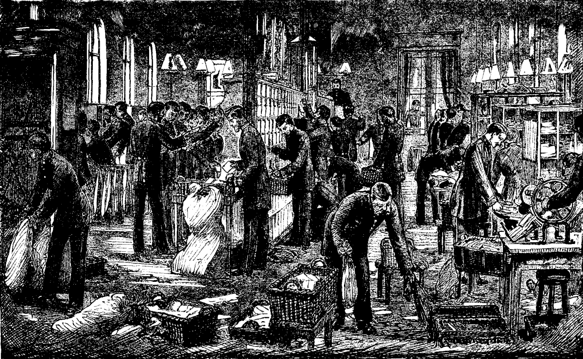
FIG. 18.—SORTING ROOM IN BERLIN POST OFFICE.
But even the Chinese carrier may not strike us so curiously as another associate, given in our next picture, Fig. 21, and yet he is a European employe from the Landes department of highly cultivated France. The inhabitants of this country buckle stilts on to their feet, so as to make their way faster through brambles and underbrush which surrounds them. The mail carrier copied them in his equipment, and thus he goes around on stilts, provided with a large cane to help him keep his balance, and furnishes a correct example of a post office official suiting the demands of every district.
While the mail in Europe has but little to do with the transportation of passengers, it is important in its activity in this respect in the large Russian empire.

FIG. 19.—DOG POST AT LAKE SUPERIOR.
The tarantass (Fig. 22), drawn by three nimble horses, flies through the endless deserts with wind-like rapidity.
The next illustration (Fig. 23) leads us to a much more remote and deserted country, "Post office on the Booby Island," occupied only by birds, and a hut containing a box in which are pens, paper, ink, and wafers. The mariners put their letters in the box, and look in to see if there is anything there addressed to them, then they continue their journey.
Postage stamps are not demanded in this ideal post office, but provision is made for the shipwrecked, by a notice informing them where they can find means of nourishment.
Once again we make a leap. The Bosnian mail carrier's equipment (Fig. 24) is, or rather was, quite singular, for our picture was taken before the occupation.
This mounted mail carrier with his weapons gives one the impression of a robber.
The task of conducting the mail through the Alps of Switzerland (Fig. 25) must be uncomfortable in winter, when the sledges glide by fearful precipices and over snow-covered passes.
Since the tariff union mail developed from the Prussian mail, and the world's mail from the tariff union, it seems suitable to close our series of pictures by representing the old Prussian postal service (Fig. 26) carried on by soldier postmen in the eighteenth century during the reign of Frederick the Great.

FIG. 20.—CHINESE POSTMAN.
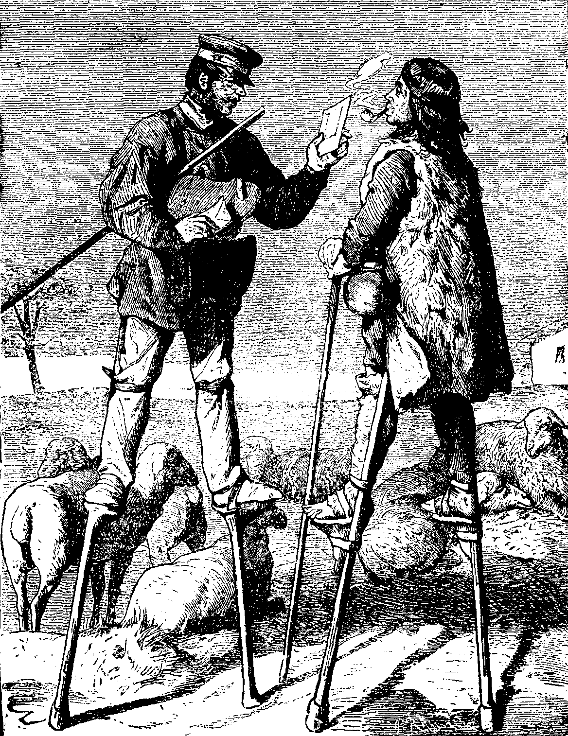
FIG. 21.—DELIVERING LETTERS IN LANDES DEPARTMENT, FRANCE.

FIG. 22.—RUSSIAN EXTRA POST.
The complaint is made that poetry is wanting in our era, and it has certainly disappeared from the postal service. One remembers that the postilion was for quite a while the favorite hero of our poets, the best of whom have sung to his praises, and given space to his melancholy thoughts of modern times in which he is pushed aside. It is too true that the post horn, formerly blown by a postilion, is now silenced, that the horse has not been able to keep up in the race with the world in its use of the steam horse, and yet how much poetry there is in that little post office all alone by itself on the Booby Island, that we have described—the sublimest poetry, that of love for mankind!
The poet of the modern postal system has not yet appeared; but he will find plenty of material. He will be able to depict the dangers a postman passes through in discharging his duty on the field, he will sing the praises of those who are injured in a railroad disaster, and yet continue their good work.
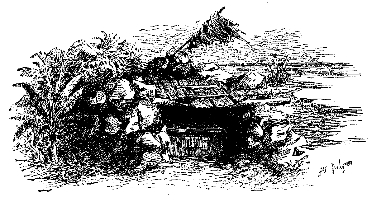
FIG. 23.—POST OFFICE ON BOOBY ISLAND.

FIG. 24.—BOSNIAN POST.
FIG. 25.—SWISS ALPINE POST IN WINTER.

FIG. 26.—SOLDIER POSTMAN OF THE EIGHTEENTH CENTURY.
He can also praise the noble thought of uniting the nations, which assumed its first tangible form in the world's mail. It will not be a sentimental song, but one full of power and indicative of our own time, in spite of those who scorn it.—Translated for the Scientific American Supplement by Jenny H. Beach, from Neue Illustrirte Zeitung.
The compound used principally for the electro-deposition of nickel is a double sulphate of nickel and ammonia. The silvery appearance of the deposit depends mainly on the purity of the salt as well as the anodes. The condition of the bath, as to age, temperature, and degree of saturation, position of anodes, strength of current, and other details of manipulation, which require care, cleanliness, and experience, such as may be met with in any intelligent workman fairly acquainted with his business, are easily acquired.
In the present paper I shall deal principally with the chemical department of this subject, and shall briefly introduce, where necessary, allusion to the mechanical and electrical details connected with the process. At a future time I shall be glad to enlarge upon this part of the subject, with a view of making the article complete.
A short time ago nickel plating was nearly as expensive as silver plating. This is explained by the fact that only a few people, at least in this country, were expert in the mechanical portions of the process, and only a very few chemists gave attention to the matter. To this must be added that our text-books were fearfully deficient in information bearing on this subject.
The salt used, and also the anodes, were originally introduced into this country from America, and latterly from Germany. I am not aware of any English manufacturer who makes a specialty in the way of anodes. This is a matter on which we can hardly congratulate ourselves, as a well known London firm some time ago supplied me with my first experimental anodes, which were in every way very superior to the German or American productions. Although the price paid per pound was greater, the plates themselves were cheaper on account of their lesser thickness.
The texture of the inner portions of these foreign anodes would lead one to infer that the metallurgy of nickel was very primitive. A good homogeneous plate can be produced, still the spongy, rotten plates of foreign manufacture were allowed the free run of our markets. The German plates are, in my opinion, more compact than the American. A serious fault with plates of earlier manufacture was their crumpled condition after a little use. This involved a difficulty in cleaning them when necessary. The English plates were not open to this objection; in fact, when the outer surfaces were planed away, they remained perfectly smooth and compact.
Large plates have been known to disintegrate and fall to pieces after being used for some time. A large anode surface, compared with that of the article to be plated, is of paramount importance. The tank should be sufficiently wide to take the largest article for plating, and to admit of the anodes being moved nearer to or further from the article. In this way the necessary electrical resistance can very conveniently be inserted between the anode and cathode surfaces. The elimination of hydrogen from the cathode must be avoided, or at any rate must not accumulate. Moving the article being plated, while in the bath, taking care not to break the electrical contacts, is a good security against a streaky or foggy appearance in the deposit.
At one time a mechanical arrangement was made, by which the cathodes were kept in motion. The addition of a little borax to the bath is a great advantage in mitigating the appearance of gas. Its behavior is electrical rather than chemical. If the anode surface is too great, a few plates should be transferred to the cathode bars.
When an article has been nickel plated, it generally presents a dull appearance, resembling frosted silver. To get over this I tried, some time ago, the use of bisulphide of carbon in the same way as used for obtaining a bright silver deposit. Curiously the deposit was very dark, almost black, which could not be buffed or polished bright. But by using a very small quantity of the bisulphide mixture, the plated surfaces were so bright that the use of polishing mops or buffs could be almost dispensed with. When we consider the amount of labor required in polishing a nickel plated article, and the impossibility of finishing off bright an undercut surface, this becomes an important addendum to the nickel plater's list of odds and ends.
This mixture is made precisely in the same way as for bright silvering, but a great deal less is to be added to the bath, about one pint per 100 gallons. It should be well stirred in, after the day's work is done, when the bath will be in proper condition for working next day. The mixture is made by shaking together, in a glass bottle, one ounce bisulphide and one gallon of the plating liquid, allow to stand until excess of bisulphide has settled, and decant the clear liquid for use as required. It is better to add this by degrees than to run the risk of overdoing. If too much is added, the bath is not of necessity spoiled, but it takes a great deal of working to bring it in order again.
About eight ounces of the double sulphate to each gallon of distilled or rain water is a good proportion to use when making up a bath. There is a slight excess with this. It is a mistake to add the salt afterward, when the bath is in good condition. The chloride and cyanide are said to give good results. I can only say that the use of either of these salts has not led to promising results in my hands.
In preparing the double sulphate, English grain nickel is decidedly the best form of metal to use. In practice, old anodes are generally used.
The metal is dissolved in a mixture of nitric and dilute sulphuric acid, with the application of a gentle heat. When sufficient metal has been dissolved, and the unused nitric acid expelled, the salt may be precipitated by a strong solution sulphate of ammonia, or, if much free acid is present, carbonate of ammonia is better to use.
Tin, lead, and portion of the iron, if present, are removed by this method. The silica, carbon, and portions of copper are left behind with the undissolved fragments of metals.
The precipitated salt, after slight washing, is dissolved in water and strong solution ammonia added. A clean iron plate is immersed in the solution to remove any trace of copper. This plate must be cleaned occasionally so as to remove any reduced copper, which will impede its action. As soon as the liquid is free from copper, it is left alkaline and well stirred so as to facilitate peroxidation and removal of iron, which forms a film on the bath. When this ceases, the liquid is rendered neutral by addition of sulphuric acid, and filtered or decanted. The solution, when properly diluted, has sp. gr. about 1.06 at 60° F. It is best to work the bath with a weak current for a short time until the liquid yields a fine white deposit. Too strong a current must be avoided.
If the copper has not been removed, it will deposit on the anodes when the bath is at rest. It should then be removed by scouring.
Copper produces a reddish tinge, which is by no means unpleasant compared with the dazzling whiteness of the nickel deposit. If this is desired, it is far better to use a separate bath, using anodes of suitable composition.
The want of adhesion between the deposited coating and the article need not be feared if cleanliness be attended to and the article, while in the bath, be not touched by the hands.
The bath should be neutral, or nearly so, slightly acid rather than alkaline. It is obvious that, as such a liquid has no detergent action on a soiled surface, scrupulous care must be taken in scouring and rinsing. Boiling alkaline solutions and a free use of powdered pumice and the scrubbing brush must on no account be neglected.
A few words on the construction of the tanks. A stout wood box, which need not be water-tight, is lined with sheet lead, the joints being blown, not soldered. An inner casing of wood which projects a few inches above the lead lining is necessary in order to avoid any chance of "short circuiting" or damage to the lead from the accidental falling of anodes or any article which might cut the lead. It is by no means a necessity that the lining should be such as to prevent the liquid getting to the lead.
On a future occasion I hope to supplement this paper with the analysis of the double sulphates used, and an account of the behavior of electrolytically prepared crucibles and dishes as compared with those now in the market.—Chem. News.
At a recent meeting of the engineering section of the Bristol Naturalists' Society a paper on "Chilled Iron" was read by Mr. Morgans, of which we give an abstract. Among the descriptions of chilled castings in common use the author instanced the following: Sheet, corn milling, and sugar rolls; tilt hammer anvils and bits, plowshares, "brasses" and bushes, cart-wheel boxes, serrated cones and cups for grinding mills, railway and tramway wheels and crossings, artillery shot and bolts, stone-breaker jaws, circular cutters, etc. Mr. Morgans then spoke of the high reputation of sheet mill rolls and wheel axle boxes made in Bristol. Of the latter in combination with wrought iron wheels and steeled axles, the local wagon works company are exporting large numbers. With respect to the strength and fatigue resistance of chilled castings, details were given of some impact tests made in July, 1864, at Pontypool, in the presence of Captain Palliser, upon some of his chilled bolts, 12¾ in. long by 4 in. diameter, made from Pontypool cold-blast pig iron. Those made from No. 1 pig iron—the most graphitic and costly—broke more easily than those from No. 2, and so on until those made from No. 4 were tested, when the maximum strength was reached. No. 4 pig iron was in fracture a pale gray, bordering on mottled. Several points regarding foundry operations in the production of chilled castings were raised for discussion. They embraced the depth of chill to be imparted to chilled rolls and railway wheels, and in the case of traction wheels, the width of chill in the tread; preparation of the chills—by coating with various carbonaceous matters, lime, beer grounds, or, occasionally, some mysterious compost—and moulds, selection and mixture of pig irons, methods and plant for melting, suitable heat for pouring, prevention of honeycombing, ferrostatic pressure of head, etc. Melting for rolls being mostly conducted in reverberatories, the variations in the condition of the furnace atmosphere, altering from reducing to oxidizing, and vice versa, in cases of bad stoking and different fuels, were referred to as occasionally affecting results. Siemens' method of melting by radiant heat was mentioned for discussion. For promoting the success of a chilled roll in its work, lathing or turning it to perfect circularity in the necks first, and then turning the body while the necks bear in steady brasses, are matters of the utmost importance.
The author next referred to the great excellence for chilling purposes possessed by some American pig irons, and to the fact that iron of a given carbon content derived from some ores and fluxes differed much in chilling properties from iron holding a similar proportion of carbon—free and combined—derived from other ores and materials. Those irons are best which develop the hardest possible chill most uniformly to the desired depth without producing a too abrupt line of division between the hard white skin and the softer gray body. A medium shading off both ways is wanted here, as in all things. The impossibility of securing a uniform quality and chemical composition in any number grade of any brand of pig iron over a lengthened period was adverted to. Consequent from this a too resolute faith in any particular make of pig iron is likely to be at times ill-requited. Occasional physical tests, accompanied with chemical analysis of irons used for chilling, were advocated; and the author was of opinion it would be well whenever a chilled casting had enjoyed a good reputation for standing up to its work, that when it was retired from work some portions of it should be chemically analyzed so as to obtain clews to compositions of excellence. Some of the physical characteristics of chilled iron, as well as the surprising locomotive properties of carbon present in heated iron, were noticed.
Attention was called to some German data, published by Dr. Percy in 1864, concerning an iron which before melting weighed—approximately—448¼ lb. per cubic foot, and contained—approximately—4 per cent. of carbon—3¼ being graphitic and ¾ combined. The chilled portion of a casting from this had a specific gravity equivalent to 471 lb. per cubic foot, and contained 5 per cent. of carbon, all combined. The soft portion of the same casting weighed 447¾ lb. per cubic foot, and contained 34.5 per cent. of carbon—31.5 being graphitic and 3.5 combined. Mr. Morgans doubted whether so great an increase in density often arises from chilling. Tool steel, when hardened by being chilled in cold water, does not become condensed, but slightly expanded from its bulk when annealed and soft. Here an increase of hardness is accompanied by a decrease of density. The gradual development of a network of cracks over the face of a chilled anvil orbit while being used in tilt hammers was mentioned. Such minute cleavages became more marked as the chill is worn down by work and from grinding. Traces of the same occurrence are observable over the surface of much worn chilled rolls used in sheet mills. In such cases the sheets get a faint diaper pattern impressed upon them. The opening of crack spaces points to lateral shrinkage of the portions of chilled material they surround, and to some release from a state of involuntary tension. If this action is accompanied by some actual densification of the fissured chill, then we have a result that possibly conflicts with the example of condensation from chilling cited by Dr. Percy.
The recent dedication of Snow Hall, at Lawrence, Kansas, is an event in the history of the State, both historic and prophetic. Since the incorporation of the University of Kansas, and before that event, there has been a steady growth of science in the State, which has culminated in Snow Hall, a building set apart for the increase and diffusion of the knowledge of natural science, as long as its massive walls shall stand. It is named in honor of the man who has been the inspiration and guiding spirit of the whole enterprise, and some incidents in his life may be of interest to the public.
Twenty years ago Professor Frank H. Snow, a recent graduate of Williams College, came to Kansas, to become a member of the faculty of the State University. His election to the chair of natural science was unexpected, as he first taught mathematics in the university, and expected in due time to become professor of Greek. As professor of the mellifluous and most plastic of all the ancient tongues, he would undoubtedly have been proficient, as his college classics still remain fresh in his warm and retentive memory, and his literary taste is so severe and chaste as to make some of his scientific papers read like a psalm. But nature designed him for another, and some think a better, field, and endowed him with powers as a naturalist that have won for him recognition among the highest living authorities of his profession.
Upon being elected to the chair of natural history, Prof. Snow entered upon his life work with an enthusiasm that charmed his associates and inspired his pupils. The true naturalist must possess large and accurate powers of observation and a love for his chosen profession that carries him over all obstacles and renders him oblivious to everything else except the specimen upon which he has set his heart. Years ago the writer was walking in the hall of the new university building in company with General Fraser and Professor Snow, when the latter suddenly darted forward up the stairs and captured an insect in its flight, that had evidently just dug its way out of the pine of the new building. In a few moments he returned with such a glow on his countenance and such a satisfied air at having captured a rare but familiar specimen, whose name was on his lips, that we both felt "Surely here is a genuine naturalist."
Some years ago an incident occurred in connection with his scientific excursions in Colorado that is quite characteristic, showing his obliviousness to self and everything else save the object of his scientific pursuit, and a fertility in overcoming danger when it meets him face to face. He was descending alone from one of the highest peaks of the Rockies, when he thought he could leave the path and reach the foot of the mountain by passing directly down its side over an immense glacier of snow and ice, and thus save time and a journey of several miles. After a while his way down the glacier grew steeper and more difficult, until he reached a point where he could not advance any further, and found, to his consternation, that he could not return by the way he had come. There he clung to the side of the immense glacier, ready, should he miss his hold, to be plunged hundreds of feet into a deep chasm. The situation flashed over him, and he knew now it was, indeed, a struggle for dear life. With a precarious foothold, he clung to the glacier with one hand, while with his pocket knife he cut a safer foothold with the other. Resting a little, he cut another foothold lower down in the hard snow, and so worked his way after a severe struggle of several hours amid constant danger to the foot of the mountain in safety. "But," continued the professor, speaking of this incident to some of his friends, "I was richly repaid for all my trouble and peril, for when I reached the foot of the mountain I captured a new and very rare species of butterfly." Multitudes of practical men cannot appreciate such devotion to pure science, but it is this absorbing passion and pure grit that enable the devotees of science to enlarge its boundaries year by year.
Once, while on a scientific excursion on the great plains, with the lamented Prof. Mudge, he nearly lost his life. He had captured a rattlesnake, and, in trying to introduce it into a jar filled with alcohol, the snake managed to bite him on the hand. The arm was immediately bound tightly with a handkerchief, and the wound enlarged with a pocket knife, and both professors took turns in sucking it as clean as possible, and ejecting the poison from their mouths. This and a heavy dose of spirits brought the professor through in safety, although the poison remaining in the wound caused considerable swelling and pain in the hand and arm. When this incident was mentioned in the Kansas Academy of Science that year, some one said, "Now we know the effect of the bite of the prairie rattlesnake on the human system. Let some one, in the interests of pure science, try the effect of the timber rattlesnake on the human system." But like the mice in the fable, no one was found who cared to put the bell on the cat.
Professors Mudge and Snow, because scientists were so few in the State at that early day, divided the field of natural science between themselves, the former taking geology and the latter living forms. Professor Mudge built up at the agricultural college a royal cabinet, easily worth $10,000, and Professor Snow has made a collection at the State University whose value cannot be readily estimated until it is catalogued and placed in cases in Snow Hall.
As a scientist, Professor Snow is an indefatigable worker, conscientious and painstaking to the last degree, never neglecting anything that can be discovered by the microscope, and when he describes and names a new species, he gives the absolute facts, without regard to theories or philosophies. For accuracy his descriptions of animal and vegetable life resemble photographs, and are received by scientists with unquestioned authority. He possesses another quality, which may be called honesty. Some scientists, whose reputation has reached other continents, cannot be trusted alone in the cabinet with the keys, for they are liable to borrow valuable specimens, and forget afterward to return them.
It is possible only to glance at the immense amount of work performed by Professor Snow during the last twenty years. Neglecting the small fry that can only be taken in nets with very fine meshes, he ascertained that there are twenty-seven species of fish in the Kansas River at Lawrence. Work on this paper occupied the leisure time of two summers, as much time in such investigations only produces negative results. For several years he worked on a catalogue of the birds of Kansas, inspiring several persons in different parts of the State to assist him. Later this work was turned over to Colonel N.S. Gross, of Topeka, an enthusiast in ornithology. Colonel Goss has a very fine collection of mounted birds in the capitol building at Topeka, and he has recently published a catalogue of the "Birds of Kansas," which contains 335 species. Professor Snow has worked faithfully on the plants of Kansas, but as other botanists came into the State, he turned the work over to their hands. For several years he has given a large share of his time and strength to entomology. Nearly every year he has led scientific excursions to different points in Colorado, New Mexico, Arizona, etc., where he might reap the best results.
Once, during a meeting of the Kansas Academy of Science, at Lawrence, Professor Snow was advertised to read a paper on some rare species of butterflies. As the hour approached, the hall in the university building was thronged, principally by ladies from the city, when Professor Snow brought out piles of his trays of butterflies, and without a note gave such an exhibit and description of his specimens as charmed the whole audience.
In meteorology, Professor Snow is an acknowledged authority, wherever this science is studied, and he has, probably, all things considered, the best meteorological record in the State.
Personally, Professor Snow possesses qualities that are worth more, perhaps, to his pupils, in forming character, than the knowledge derived from him as an instructor. His life is pure and ennobling, his presence inspiring, and many young men have gone from his lecture room to hold good positions in the scientific world. When one sees him in his own home, surrounded by his family, with books and specimens and instruments all around, he feels that the ideal home has not lost everything in the fall.
Snow Hall is the natural resultant of twenty years of earnest and faithful labor on the part of this eminent scientist. The regents displayed the rare good sense of committing everything regarding the plans of the building, and the form and arrangement of the cases, to Professor Snow, which has resulted in giving to Kansas the model building of its kind in the West, if not in this country. Very large collections have accumulated at the State University, under the labors of Professor Snow and his assistants, which need to be classified, arranged, and labeled; and when the legislature appropriates the money to furnish cases to display this collection in almost every department of natural science, Kansas will possess a hall of natural science whose influence will be felt throughout the State, and be an attraction to scientists everywhere.—Chaplain J.D. Parker, in Kansas City Journal.
A study of the means by which nature rids the economy of what is harmful has been made by Sanquirico, of Siena, and his experiments and conclusions are as follows:
He finds that the vessels of the body, without undergoing extensive structural alteration, can by exosmosis rid themselves of fluid to an amount of eight per cent. of the body weight of the subject of the experiment.
Through the injection of neutral fluids a great increase in the vascular tension is effected, which is relieved by elimination through the kidneys.
With reference to this fact, the author, in 1885, made experiments with alcohol and strychnine, and continued his researches in the use of chloral and aconitine with results favorable to the method employed, which is as follows:
The minimal fatal dose of a given poison was selected, and found to be in a certain relation to the body weight.
Immediately upon the injection of the poison a solution of sodium chloride, 0.75 per cent. in strength, was injected into the subcutaneous tissues of the neck, in quantities being eight per cent. of the body weight of the animal.
In the case of those poisons whose effect is not instantaneous, the injection of saline solution was made on the first appearance of toxic symptoms. In other poisons the injection was made at once.
The result of the use of salines was a diuresis varying in the promptness of its appearance and in its amount.
Those animals in which diuresis was limited at first and then increased generally recovered, while those in which diuresis was not established perished. The poison used was found in the urine of those which died and also those which recovered.
The author succeeded in rescuing animals poisoned by alcohol, strychnine, chloral, and aconitine. With morphine, curare, and hypnone, the method of elimination failed, although ten per cent. in quantity of the body weight of the animal was used in the saline injection. With aconitine, diuresis was not always established, and when it failed the animal died in convulsions.—Centralblatt fur die Medicinischen Wissenschaften, December 18, 1886.
A catalogue, containing brief notices of many important scientific papers heretofore published in the SUPPLEMENT, may be had gratis at this office.
Sent by mail, postage prepaid, to subscribers in any part of the United States or Canada. Six dollars a year, sent, prepaid, to any foreign country.
All the back numbers of THE SUPPLEMENT, from the commencement, January 1, 1876, can be had. Price, 10 cents each.
All the back volumes of THE SUPPLEMENT can likewise be supplied. Two volumes are issued yearly. Price of each volume, $2.50, stitched in paper, or $3.50, bound in stiff covers.
COMBINED RATES—One copy of SCIENTIFIC AMERICAN and one copy of SCIENTIFIC AMERICAN SUPPLEMENT, one year, postpaid, $7.00.
A liberal discount to booksellers, news agents, and canvassers.
MUNN & CO., Publishers,
361 Broadway, New York, N.Y.
In connection with the Scientific American, Messrs. MUNN & Co. are Solicitors of American and Foreign Patents, have had 42 years' experience, and now have the largest establishment in the world. Patents are obtained on the best terms.
A special notice is made in the Scientific American of all Inventions patented through this Agency, with the name and residence of the Patentee. By the immense circulation thus given, public attention is directed to the merits of the new patent, and sales or introduction often easily effected.
Any person who has made a new discovery or invention can ascertain, free of charge, whether a patent can probably be obtained, by writing to MUNN & Co.
We also send free our Hand Book about the Patent Laws, Patents, Caveats. Trade Marks, their costs, and how procured. Address
MUNN & CO., 361 Broadway, New York.
Branch Office, 622 and 624 F St., Washington, D.C.
End of the Project Gutenberg EBook of Scientific American Supplement, No.
586, March 26, 1887, by Various

*** END OF THIS PROJECT GUTENBERG EBOOK SCIENTIFIC AMERICAN 586 ***

***** This file should be named 11736-h.htm or 11736-h.zip *****
This and all associated files of various formats will be found in:
        https://www.gutenberg.org/1/1/7/3/11736/

Produced by Don Kretz, Juliet Sutherland, Charles Franks and the DP Team

Updated editions will replace the previous one--the old editions
will be renamed.

Creating the works from public domain print editions means that no
one owns a United States copyright in these works, so the Foundation
(and you!) can copy and distribute it in the United States without
permission and without paying copyright royalties.  Special rules,
set forth in the General Terms of Use part of this license, apply to
copying and distributing Project Gutenberg-tm electronic works to
protect the PROJECT GUTENBERG-tm concept and trademark.  Project
Gutenberg is a registered trademark, and may not be used if you
charge for the eBooks, unless you receive specific permission.  If you
do not charge anything for copies of this eBook, complying with the
rules is very easy.  You may use this eBook for nearly any purpose
such as creation of derivative works, reports, performances and
research.  They may be modified and printed and given away--you may do
practically ANYTHING with public domain eBooks.  Redistribution is
subject to the trademark license, especially commercial
redistribution.


*** START: FULL LICENSE ***

THE FULL PROJECT GUTENBERG LICENSE
PLEASE READ THIS BEFORE YOU DISTRIBUTE OR USE THIS WORK

To protect the Project Gutenberg-tm mission of promoting the free
distribution of electronic works, by using or distributing this work
(or any other work associated in any way with the phrase "Project
Gutenberg"), you agree to comply with all the terms of the Full Project
Gutenberg-tm License (available with this file or online at
https://gutenberg.org/license).


Section 1.  General Terms of Use and Redistributing Project Gutenberg-tm
electronic works

1.A.  By reading or using any part of this Project Gutenberg-tm
electronic work, you indicate that you have read, understand, agree to
and accept all the terms of this license and intellectual property
(trademark/copyright) agreement.  If you do not agree to abide by all
the terms of this agreement, you must cease using and return or destroy
all copies of Project Gutenberg-tm electronic works in your possession.
If you paid a fee for obtaining a copy of or access to a Project
Gutenberg-tm electronic work and you do not agree to be bound by the
terms of this agreement, you may obtain a refund from the person or
entity to whom you paid the fee as set forth in paragraph 1.E.8.

1.B.  "Project Gutenberg" is a registered trademark.  It may only be
used on or associated in any way with an electronic work by people who
agree to be bound by the terms of this agreement.  There are a few
things that you can do with most Project Gutenberg-tm electronic works
even without complying with the full terms of this agreement.  See
paragraph 1.C below.  There are a lot of things you can do with Project
Gutenberg-tm electronic works if you follow the terms of this agreement
and help preserve free future access to Project Gutenberg-tm electronic
works.  See paragraph 1.E below.

1.C.  The Project Gutenberg Literary Archive Foundation ("the Foundation"
or PGLAF), owns a compilation copyright in the collection of Project
Gutenberg-tm electronic works.  Nearly all the individual works in the
collection are in the public domain in the United States.  If an
individual work is in the public domain in the United States and you are
located in the United States, we do not claim a right to prevent you from
copying, distributing, performing, displaying or creating derivative
works based on the work as long as all references to Project Gutenberg
are removed.  Of course, we hope that you will support the Project
Gutenberg-tm mission of promoting free access to electronic works by
freely sharing Project Gutenberg-tm works in compliance with the terms of
this agreement for keeping the Project Gutenberg-tm name associated with
the work.  You can easily comply with the terms of this agreement by
keeping this work in the same format with its attached full Project
Gutenberg-tm License when you share it without charge with others.

1.D.  The copyright laws of the place where you are located also govern
what you can do with this work.  Copyright laws in most countries are in
a constant state of change.  If you are outside the United States, check
the laws of your country in addition to the terms of this agreement
before downloading, copying, displaying, performing, distributing or
creating derivative works based on this work or any other Project
Gutenberg-tm work.  The Foundation makes no representations concerning
the copyright status of any work in any country outside the United
States.

1.E.  Unless you have removed all references to Project Gutenberg:

1.E.1.  The following sentence, with active links to, or other immediate
access to, the full Project Gutenberg-tm License must appear prominently
whenever any copy of a Project Gutenberg-tm work (any work on which the
phrase "Project Gutenberg" appears, or with which the phrase "Project
Gutenberg" is associated) is accessed, displayed, performed, viewed,
copied or distributed:

This eBook is for the use of anyone anywhere at no cost and with
almost no restrictions whatsoever.  You may copy it, give it away or
re-use it under the terms of the Project Gutenberg License included
with this eBook or online at www.gutenberg.org

1.E.2.  If an individual Project Gutenberg-tm electronic work is derived
from the public domain (does not contain a notice indicating that it is
posted with permission of the copyright holder), the work can be copied
and distributed to anyone in the United States without paying any fees
or charges.  If you are redistributing or providing access to a work
with the phrase "Project Gutenberg" associated with or appearing on the
work, you must comply either with the requirements of paragraphs 1.E.1
through 1.E.7 or obtain permission for the use of the work and the
Project Gutenberg-tm trademark as set forth in paragraphs 1.E.8 or
1.E.9.

1.E.3.  If an individual Project Gutenberg-tm electronic work is posted
with the permission of the copyright holder, your use and distribution
must comply with both paragraphs 1.E.1 through 1.E.7 and any additional
terms imposed by the copyright holder.  Additional terms will be linked
to the Project Gutenberg-tm License for all works posted with the
permission of the copyright holder found at the beginning of this work.

1.E.4.  Do not unlink or detach or remove the full Project Gutenberg-tm
License terms from this work, or any files containing a part of this
work or any other work associated with Project Gutenberg-tm.

1.E.5.  Do not copy, display, perform, distribute or redistribute this
electronic work, or any part of this electronic work, without
prominently displaying the sentence set forth in paragraph 1.E.1 with
active links or immediate access to the full terms of the Project
Gutenberg-tm License.

1.E.6.  You may convert to and distribute this work in any binary,
compressed, marked up, nonproprietary or proprietary form, including any
word processing or hypertext form.  However, if you provide access to or
distribute copies of a Project Gutenberg-tm work in a format other than
"Plain Vanilla ASCII" or other format used in the official version
posted on the official Project Gutenberg-tm web site (www.gutenberg.org),
you must, at no additional cost, fee or expense to the user, provide a
copy, a means of exporting a copy, or a means of obtaining a copy upon
request, of the work in its original "Plain Vanilla ASCII" or other
form.  Any alternate format must include the full Project Gutenberg-tm
License as specified in paragraph 1.E.1.

1.E.7.  Do not charge a fee for access to, viewing, displaying,
performing, copying or distributing any Project Gutenberg-tm works
unless you comply with paragraph 1.E.8 or 1.E.9.

1.E.8.  You may charge a reasonable fee for copies of or providing
access to or distributing Project Gutenberg-tm electronic works provided
that

- You pay a royalty fee of 20% of the gross profits you derive from
     the use of Project Gutenberg-tm works calculated using the method
     you already use to calculate your applicable taxes.  The fee is
     owed to the owner of the Project Gutenberg-tm trademark, but he
     has agreed to donate royalties under this paragraph to the
     Project Gutenberg Literary Archive Foundation.  Royalty payments
     must be paid within 60 days following each date on which you
     prepare (or are legally required to prepare) your periodic tax
     returns.  Royalty payments should be clearly marked as such and
     sent to the Project Gutenberg Literary Archive Foundation at the
     address specified in Section 4, "Information about donations to
     the Project Gutenberg Literary Archive Foundation."

- You provide a full refund of any money paid by a user who notifies
     you in writing (or by e-mail) within 30 days of receipt that s/he
     does not agree to the terms of the full Project Gutenberg-tm
     License.  You must require such a user to return or
     destroy all copies of the works possessed in a physical medium
     and discontinue all use of and all access to other copies of
     Project Gutenberg-tm works.

- You provide, in accordance with paragraph 1.F.3, a full refund of any
     money paid for a work or a replacement copy, if a defect in the
     electronic work is discovered and reported to you within 90 days
     of receipt of the work.

- You comply with all other terms of this agreement for free
     distribution of Project Gutenberg-tm works.

1.E.9.  If you wish to charge a fee or distribute a Project Gutenberg-tm
electronic work or group of works on different terms than are set
forth in this agreement, you must obtain permission in writing from
both the Project Gutenberg Literary Archive Foundation and Michael
Hart, the owner of the Project Gutenberg-tm trademark.  Contact the
Foundation as set forth in Section 3 below.

1.F.

1.F.1.  Project Gutenberg volunteers and employees expend considerable
effort to identify, do copyright research on, transcribe and proofread
public domain works in creating the Project Gutenberg-tm
collection.  Despite these efforts, Project Gutenberg-tm electronic
works, and the medium on which they may be stored, may contain
"Defects," such as, but not limited to, incomplete, inaccurate or
corrupt data, transcription errors, a copyright or other intellectual
property infringement, a defective or damaged disk or other medium, a
computer virus, or computer codes that damage or cannot be read by
your equipment.

1.F.2.  LIMITED WARRANTY, DISCLAIMER OF DAMAGES - Except for the "Right
of Replacement or Refund" described in paragraph 1.F.3, the Project
Gutenberg Literary Archive Foundation, the owner of the Project
Gutenberg-tm trademark, and any other party distributing a Project
Gutenberg-tm electronic work under this agreement, disclaim all
liability to you for damages, costs and expenses, including legal
fees.  YOU AGREE THAT YOU HAVE NO REMEDIES FOR NEGLIGENCE, STRICT
LIABILITY, BREACH OF WARRANTY OR BREACH OF CONTRACT EXCEPT THOSE
PROVIDED IN PARAGRAPH F3.  YOU AGREE THAT THE FOUNDATION, THE
TRADEMARK OWNER, AND ANY DISTRIBUTOR UNDER THIS AGREEMENT WILL NOT BE
LIABLE TO YOU FOR ACTUAL, DIRECT, INDIRECT, CONSEQUENTIAL, PUNITIVE OR
INCIDENTAL DAMAGES EVEN IF YOU GIVE NOTICE OF THE POSSIBILITY OF SUCH
DAMAGE.

1.F.3.  LIMITED RIGHT OF REPLACEMENT OR REFUND - If you discover a
defect in this electronic work within 90 days of receiving it, you can
receive a refund of the money (if any) you paid for it by sending a
written explanation to the person you received the work from.  If you
received the work on a physical medium, you must return the medium with
your written explanation.  The person or entity that provided you with
the defective work may elect to provide a replacement copy in lieu of a
refund.  If you received the work electronically, the person or entity
providing it to you may choose to give you a second opportunity to
receive the work electronically in lieu of a refund.  If the second copy
is also defective, you may demand a refund in writing without further
opportunities to fix the problem.

1.F.4.  Except for the limited right of replacement or refund set forth
in paragraph 1.F.3, this work is provided to you 'AS-IS', WITH NO OTHER
WARRANTIES OF ANY KIND, EXPRESS OR IMPLIED, INCLUDING BUT NOT LIMITED TO
WARRANTIES OF MERCHANTIBILITY OR FITNESS FOR ANY PURPOSE.

1.F.5.  Some states do not allow disclaimers of certain implied
warranties or the exclusion or limitation of certain types of damages.
If any disclaimer or limitation set forth in this agreement violates the
law of the state applicable to this agreement, the agreement shall be
interpreted to make the maximum disclaimer or limitation permitted by
the applicable state law.  The invalidity or unenforceability of any
provision of this agreement shall not void the remaining provisions.

1.F.6.  INDEMNITY - You agree to indemnify and hold the Foundation, the
trademark owner, any agent or employee of the Foundation, anyone
providing copies of Project Gutenberg-tm electronic works in accordance
with this agreement, and any volunteers associated with the production,
promotion and distribution of Project Gutenberg-tm electronic works,
harmless from all liability, costs and expenses, including legal fees,
that arise directly or indirectly from any of the following which you do
or cause to occur: (a) distribution of this or any Project Gutenberg-tm
work, (b) alteration, modification, or additions or deletions to any
Project Gutenberg-tm work, and (c) any Defect you cause.


Section  2.  Information about the Mission of Project Gutenberg-tm

Project Gutenberg-tm is synonymous with the free distribution of
electronic works in formats readable by the widest variety of computers
including obsolete, old, middle-aged and new computers.  It exists
because of the efforts of hundreds of volunteers and donations from
people in all walks of life.

Volunteers and financial support to provide volunteers with the
assistance they need, is critical to reaching Project Gutenberg-tm's
goals and ensuring that the Project Gutenberg-tm collection will
remain freely available for generations to come.  In 2001, the Project
Gutenberg Literary Archive Foundation was created to provide a secure
and permanent future for Project Gutenberg-tm and future generations.
To learn more about the Project Gutenberg Literary Archive Foundation
and how your efforts and donations can help, see Sections 3 and 4
and the Foundation web page at https://www.pglaf.org.


Section 3.  Information about the Project Gutenberg Literary Archive
Foundation

The Project Gutenberg Literary Archive Foundation is a non profit
501(c)(3) educational corporation organized under the laws of the
state of Mississippi and granted tax exempt status by the Internal
Revenue Service.  The Foundation's EIN or federal tax identification
number is 64-6221541.  Its 501(c)(3) letter is posted at
https://pglaf.org/fundraising.  Contributions to the Project Gutenberg
Literary Archive Foundation are tax deductible to the full extent
permitted by U.S. federal laws and your state's laws.

The Foundation's principal office is located at 4557 Melan Dr. S.
Fairbanks, AK, 99712., but its volunteers and employees are scattered
throughout numerous locations.  Its business office is located at
809 North 1500 West, Salt Lake City, UT 84116, (801) 596-1887, email
business@pglaf.org.  Email contact links and up to date contact
information can be found at the Foundation's web site and official
page at https://pglaf.org

For additional contact information:
     Dr. Gregory B. Newby
     Chief Executive and Director
     gbnewby@pglaf.org

Section 4.  Information about Donations to the Project Gutenberg
Literary Archive Foundation

Project Gutenberg-tm depends upon and cannot survive without wide
spread public support and donations to carry out its mission of
increasing the number of public domain and licensed works that can be
freely distributed in machine readable form accessible by the widest
array of equipment including outdated equipment.  Many small donations
($1 to $5,000) are particularly important to maintaining tax exempt
status with the IRS.

The Foundation is committed to complying with the laws regulating
charities and charitable donations in all 50 states of the United
States.  Compliance requirements are not uniform and it takes a
considerable effort, much paperwork and many fees to meet and keep up
with these requirements.  We do not solicit donations in locations
where we have not received written confirmation of compliance.  To
SEND DONATIONS or determine the status of compliance for any
particular state visit https://pglaf.org

While we cannot and do not solicit contributions from states where we
have not met the solicitation requirements, we know of no prohibition
against accepting unsolicited donations from donors in such states who
approach us with offers to donate.

International donations are gratefully accepted, but we cannot make
any statements concerning tax treatment of donations received from
outside the United States.  U.S. laws alone swamp our small staff.

Please check the Project Gutenberg Web pages for current donation
methods and addresses.  Donations are accepted in a number of other
ways including including checks, online payments and credit card
donations.  To donate, please visit: https://pglaf.org/donate


Section 5.  General Information About Project Gutenberg-tm electronic
works.

Professor Michael S. Hart was the originator of the Project Gutenberg-tm
concept of a library of electronic works that could be freely shared
with anyone.  For thirty years, he produced and distributed Project
Gutenberg-tm eBooks with only a loose network of volunteer support.

Project Gutenberg-tm eBooks are often created from several printed
editions, all of which are confirmed as Public Domain in the U.S.
unless a copyright notice is included.  Thus, we do not necessarily
keep eBooks in compliance with any particular paper edition.

Each eBook is in a subdirectory of the same number as the eBook's
eBook number, often in several formats including plain vanilla ASCII,
compressed (zipped), HTML and others.

Corrected EDITIONS of our eBooks replace the old file and take over
the old filename and etext number.  The replaced older file is renamed.
VERSIONS based on separate sources are treated as new eBooks receiving
new filenames and etext numbers.

Most people start at our Web site which has the main PG search facility:

     https://www.gutenberg.org

This Web site includes information about Project Gutenberg-tm,
including how to make donations to the Project Gutenberg Literary
Archive Foundation, how to help produce our new eBooks, and how to
subscribe to our email newsletter to hear about new eBooks.

EBooks posted prior to November 2003, with eBook numbers BELOW #10000,
are filed in directories based on their release date.  If you want to
download any of these eBooks directly, rather than using the regular
search system you may utilize the following addresses and just
download by the etext year. For example:

     https://www.gutenberg.org/etext06

    (Or /etext 05, 04, 03, 02, 01, 00, 99,
     98, 97, 96, 95, 94, 93, 92, 92, 91 or 90)

EBooks posted since November 2003, with etext numbers OVER #10000, are
filed in a different way.  The year of a release date is no longer part
of the directory path.  The path is based on the etext number (which is
identical to the filename).  The path to the file is made up of single
digits corresponding to all but the last digit in the filename.  For
example an eBook of filename 10234 would be found at:

     https://www.gutenberg.org/1/0/2/3/10234

or filename 24689 would be found at:
     https://www.gutenberg.org/2/4/6/8/24689

An alternative method of locating eBooks:
     https://www.gutenberg.org/GUTINDEX.ALL