
The Project Gutenberg EBook of Scientific American Supplement, No. 460,
October 25, 1884, by Various

This eBook is for the use of anyone anywhere at no cost and with
almost no restrictions whatsoever.  You may copy it, give it away or
re-use it under the terms of the Project Gutenberg License included
with this eBook or online at www.gutenberg.org


Title: Scientific American Supplement, No. 460, October 25, 1884

Author: Various

Release Date: March 28, 2004 [EBook #11734]

Language: English

Character set encoding: ISO-8859-1

*** START OF THIS PROJECT GUTENBERG EBOOK  SCIENTIFIC AMERICAN 460 ***


Produced by Don Kretz, Juliet Sutherland, Charles Franks and the DP Team
It is, perhaps, more difficult to write accurate history than anything else, and this is true not only of nations, kings, politicians, or wars, but of events and things witnessed or called into existence in every-day life. In The Engineer for September 17, 1880, we did our best to place a true statement of the facts concerning the Rocket before our readers. In many respects this was the most remarkable steam engine ever built, and about it there ought to be no difficulty, one would imagine, in arriving at the truth. It was for a considerable period the cynosure of all eyes. Engineers all over the world were interested in its performance. Drawings were made of it; accounts were written of it, descriptions of it abounded. Little more than half a century has elapsed since it startled the world by its performance at Rainhill, and yet it is not too much to say that the truth—the whole truth, that is to say—can never now be written. We are, however, able to put some facts before our readers now which have never before been published, which are sufficiently startling, and while supplying a missing link in the history of the locomotive, go far to show that much that has hitherto been held to be true is not true at all.
When the Liverpool and Manchester Railway was opened on the 15th of September, 1830, among those present was James Nasmyth, subsequently the inventor of the steam hammer. Mr. Nasmyth was a good freehand draughtsman, and he sketched the Rocket as it stood on the line. The sketch is still in existence. Mr. Nasmyth has placed this sketch at our disposal, thus earning the gratitude of our readers, and we have reproduced as nearly as possible, but to a somewhat enlarged scale, this invaluable link in the history of the locomotive. Mr. Nasmyth writes concerning it, July 26, 1884: "This slight and hasty sketch of the Rocket was made the day before the opening of the Manchester and Liverpool Railway, September 12, 1830. I availed myself of the opportunity of a short pause in the experimental runs with the Rocket, of three or four miles between Liverpool and Rainhill, George Stephenson acting as engine driver and his son Robert as stoker. The limited time I had for making my sketch prevented me from making a more elaborate one, but such as it is, all the important and characteristic details are given; but the pencil lines, after the lapse of fifty-four years, have become somewhat indistinct." The pencil drawing, more than fifty years old, has become so faint that its reproduction has become a difficult task. Enough remains, however, to show very clearly what manner of engine this Rocket was. For the sake of comparison we reproduce an engraving of the Rocket of 1829. A glance will show that an astonishing transformation had taken place in the eleven months which had elapsed between the Rainhill trials and the opening of the Liverpool and Manchester Railway. We may indicate a few of the alterations. In 1829 the cylinders were set at a steep angle; in 1830 they were nearly horizontal. In 1829 the driving wheels were of wood; in 1830 they were of cast iron. In 1829 there was no smoke-box proper, and a towering chimney; in 1830 there was a smoke-box and a comparatively short chimney. In 1829 a cask and a truck constituted the tender; in 1830 there was a neatly designed tender, not very different in style from that still in use on the Great Western broad gauge. All these things may perhaps be termed concomitants, or changes in detail. But there is a radical difference yet to be considered. In 1829 the fire-box was a kind of separate chamber tacked on to the back of the barrel of the boiler, and communicating with it by three tubes; one on each side united the water spaces, and one at the top the steam spaces. In 1830 all this had disappeared, and we find in Mr. Nasmyth's sketch a regular fire-box, such as is used to this moment. In one word, the Rocket of 1829 is different from the Rocket of 1830 in almost every conceivable respect; and we are driven perforce to the conclusion that the Rocket of 1829 never worked at all on the Liverpool and Manchester Railway; the engine of 1830 was an entirely new engine. We see no possible way of escaping from this conclusion. The most that can be said against it is that the engine underwent many alterations. The alterations must, however, have been so numerous that they were tantamount to the construction of a new engine. It is difficult, indeed, to see what part of the old engine could exist in the new one; some plates of the boiler shell might, perhaps, have been retained, but we doubt it. It may, perhaps, disturb some hitherto well rooted beliefs to say so, but it seems to us indisputable that the Rocket of 1829 and 1830 were totally different engines.
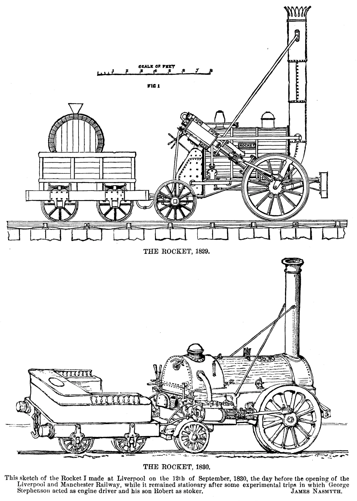
FIG. 1. THE ROCKET, 1829. THE ROCKET, 1830.
Our engraving, Fig. 1, is copied from a drawing made by Mr. Phipps, M.I.C.E., who was employed by Messrs. Stephenson to compile a drawing of the Rocket from such drawings and documents as could be found. This gentleman had made the original drawings of the Rocket of 1829, under Messrs. G. & R. Stephenson's direction. Mr. Phipps is quite silent about the history of the engine during the eleven months between the Rainhill trials and the opening of the railway. In this respect he is like every one else. This period is a perfect blank. It is assumed that from Rainhill the engine went back to Messrs. Stephenson's works; but there is nothing on the subject in print, so far as we are aware. Mr. G.R. Stephenson lent us in 1880 a working model of the Rocket. An engraving of this will be found in The Engineer for September 17, 1880. The difference between it and the engraving below, prepared from Mr. Phipps' drawing, is, it will be seen, very small—one of proportions more than anything else. Mr. Stephenson says of his model: "I can say that it is a very fair representation of what the engine was before she was altered." Hitherto it has always been taken for granted that the alteration consisted mainly in reducing the angle at which the cylinders were set. The Nasmyth drawing alters the whole aspect of the question, and we are now left to speculate as to what became of the original Rocket. We are told that after "it" left the railway it was employed by Lord Dundonald to supply steam to a rotary engine; then it propelled a steamboat; next it drove small machinery in a shop in Manchester; then it was employed in a brickyard; eventually it was purchased as a curiosity by Mr. Thomson, of Kirkhouse, near Carlisle, who sent it to Messrs. Stephenson to take care of. With them it remained for years. Then Messrs. Stephenson put it into something like its original shape, and it went to South Kensington Museum, where "it" is now. The question is, What engine is this? Was it the Rocket of 1829 or the Rocket of 1830, or neither? It could not be the last, as will be understood from Mr. Nasmyth's drawing; if we bear in mind that the so-called fire-box on the South Kensington engine is only a sham made of thin sheet iron without water space, while the fire-box shown in Mr. Nasmyth's engine is an integral part of the whole, which could not have been cut off. That is to say, Messrs. Stephenson, in getting the engine put in order for the Patent Office Museum, certainly did not cut off the fire-box shown in Mr. Nasmyth's sketch, and replace it with the sham box now on the boiler. If our readers will turn to our impression for the 30th of June, 1876, they will find a very accurate engraving of the South Kensington engine, which they can compare with Mr. Nasmyth's sketch, and not fail to perceive that the differences are radical.
In "Wood on Railroads," second edition, 1832, page 377, we are told that "after those experiments"—the Rainhill trials—"were concluded, the Novelty underwent considerable alterations;" and on page 399, "Mr. Stephenson had also improved the working of the Rocket engine, and by applying the steam more powerfully in the chimney to increase the draught, was enabled to raise a much greater quantity of steam than before." Nothing is said as to where the new experiments took place, nor their precise date. But it seems that the Meteor and the Arrow—Stephenson engines—were tried at the same time; and this is really the only hint Wood gives as to what was done to the Rocket between the 6th of October, 1829, and the 15th of September, 1830.
There are men still alive who no doubt could clear up the question at issue, and it is much to be hoped that they will do so. As the matter now stands, it will be seen that we do not so much question that the Rocket in South Kensington Museum is, in part perhaps, the original Rocket of Rainhill celebrity, as that it ever ran in regular service on the Liverpool and Manchester Railway. Yet, if not, then we may ask, what became of the Rocket of 1830? It is not at all improbable that the first Rocket was cast on one side, until it was bought by Lord Dundonald, and that its history is set out with fair accuracy above. But the Rocket of the Manchester and Liverpool Railway is hardly less worthy of attention than its immediate predecessor, and concerning it information is needed. Any scrap of information, however apparently trifling, that can be thrown on this subject by our readers will be highly valued, and given an appropriate place in our pages.—The Engineer.
The largest grain elevator in the world, says the Nashville American, is that just constructed at Newport News under the auspices of the Chesapeake & Ohio Railway Co. It is 90 ft. wide, 386 ft. long, and about 164 ft. high, with engine and boiler rooms 40 × 100 ft. and 40 ft. high. In its construction there were used about 3,000 piles, 100,000 ft. of white-oak timber, 82,000 cu. ft. of stone, 800,000 brick, 6,000,000 ft. of pine and spruce lumber, 4,500 kegs of nails, 6 large boilers, 2 large engines, 200 tons of machinery, 20 large hopper-scales, and 17,200 ft. of rubber belts, from 8 to 48 in. wide and 50 to 1,700 ft. long; in addition, there were 8,000 elevator buckets, and other material. The storage capacity is 1,600,000 bushels, with a receiving capacity of 30,000, and a shipping capacity of 20,000 bushels per hour.
Literature relating to turbines probably stands unrivaled among all that concerns questions of hydraulic engineering, not so much in its voluminous character as in the extent to which purely theoretical writers have ignored facts, or practical writers have relied upon empirical rules rather than upon any sound theory. In relation to this view, it may suffice to note that theoretical deductions have frequently been based upon a generalization that "streams of water must enter the buckets of a turbine without shock, and leave them without velocity." Both these assumed conditions are misleading, and it is now well known that in every good turbine both are carefully disobeyed. So-called practical writers, as a rule, fail to give much useful information, and their task seems rather in praise of one description of turbine above another. But generally, it is of no consequence whatever how a stream of water may be led through the buckets of any form of turbine, so long as its velocity gradually becomes reduced to the smallest amount that will carry it freely clear of the machine.
The character of theoretical information imparted by some Chicago Journal of Commerce, dated 20th February, 1884. There we are informed that "the height of the fall is one of the most important considerations, as the same stream of water will furnish five times the horse power at ten ft. that it will at five ft. fall." By general consent twice two are four, but it has been reserved for this imaginative writer to make the useful discovery that sometimes twice two are ten. Not until after the translation of Captain Morris' work on turbines by Mr. E. Morris in 1844, was attention in America directed to the advantages which these motors possessed over the gravity wheels then in use. A duty of 75 per cent. was then obtained, and a further study of the subject by a most acute and practical engineer, Mr. Boyden, led to various improvements upon Mr. Fauneyron's model, by which his experiments indicated the high duty of 88 per cent. The most conspicuous addition made by Mr. Boyden was the diffuser. The ingenious contrivance had the effect of transforming part of whatever velocity remained in the stream after passing out of a turbine into an atmospheric pressure, by which the corresponding lost head became effective, and added about 3 per cent. to the duty obtained. It may be worth noticing that, by an accidental application of these principles to some inward flow turbines, there is obtained most, if not all, of whatever advantage they are supposed to possess, but oddly enough this genuine advantage is never mentioned by any of the writers who are interested in their introduction or sale. The well-known experiments of Mr. James B. Francis in 1857, and his elaborate report, gave to hydraulic engineers a vast store of useful data, and since that period much progress has been made in the construction of turbines, and literature on the subject has become very complete.
In the limits of a short paper it is impossible to do justice to more than one aspect of the considerations relating to turbines, and it is now proposed to bring before the Mechanical Section of the British Association some conclusions drawn from the behavior of jets of water discharged under pressure, more particularly in the hope that, as water power is extremely abundant in Canada, any remarks relating to the subject may not fail to prove interesting.
Between the action of turbines and that of screw propellers exists an exact parallelism, although in one case water imparts motion to the buckets of a turbine, while in the other case blades of a screw give spiral movement to a column of water driven aft from the vessel it propels forward. Turbines have been driven sometimes by impact alone, sometimes by reaction above, though generally by a combination of impact and reaction, and it is by the last named system that the best results are now known to be obtained.
The ordinary paddles of a steamer impel a mass of water horizontally backward by impact alone, but screw propellers use reaction somewhat disguised, and only to a limited extent. The full use and advantages of reaction for screw propellers were not generally known until after the publication of papers by the present writer in the "Proceedings" of the Institution of Naval Architects for 1867 and 1868, and more fully in the "Transactions" of the Society of Engineers for 1868. Since that time, by the author of these investigations then described, by the English Admiralty, and by private firms, further experiments have been carried out, some on a considerable scale, and all corroborative of the results published in 1868. But nothing further has been done in utilizing these discoveries until the recent exigencies of modern naval warfare have led foreign nations to place a high value upon speed. Some makers of torpedo boats have thus been induced to slacken the trammels of an older theory and to apply a somewhat incomplete form of the author's reaction propeller for gaining some portion of the notable performance of these hornets of the deep. Just as in turbines a combination of impact and reaction produces the maximum practical result, so in screw propellers does a corresponding gain accompany the same construction.
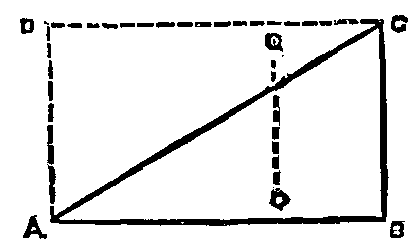
FIG. 1.
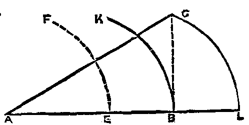
FIG. 2.
Turbines.—While studying those effects produced by jets of water impinging upon plain or concave surfaces corresponding to buckets of turbines, it simplifies matters to separate these results due to impact from others due to reaction. And it will be well at the outset to draw a distinction between the nature of these two pressures, and to remind ourselves of the laws which lie at the root and govern the whole question under present consideration. Water obeys the laws of gravity, exactly like every other body; and the velocity with which any quantity may be falling is an expression of the full amount of work it contains. By a sufficiently accurate practical rule this velocity is eight times the square root of the head or vertical column measured in feet. Velocity per second = 8 sqrt (head in feet), therefore, for a head of 100 ft. as an example, V = 8 sqrt (100) = 80 ft. per second. The graphic method of showing velocities or pressures has many advantages, and is used in all the following diagrams. Beginning with purely theoretical considerations, we must first recollect that there is no such thing as absolute motion. All movements are relative to something else, and what we have to do with a stream of water in a turbine is to reduce its velocity relatively to the earth, quite a different thing to its velocity in relation to the turbine; for while the one may be zero, the other may be anything we please. ABCD in Fig. 1 represents a parallelogram of velocities, wherein AC gives the direction of a jet of water starting at A, and arriving at C at the end of one second or any other division of time. At a scale of 1/40 in. to 1 ft., AC represents 80 ft., the fall due to 100 ft. head, or at a scale of 1 in. to 1 ft., AC gives 2 ft., or the distance traveled by the same stream in 1/40 of a second. The velocity AC may be resolved into two others, namely, AB and AD, or BC, which are found to be 69.28 ft. and 40 ft. respectively, when the angle BAC—generally called x in treatises on turbines—is 30 deg. If, however, AC is taken at 2 ft., then A B will be found = 20.78 in., and BC = 12 in. for a time of 1/40 or 0.025 of a second. Supposing now a flat plate, BC = 12 in. wide move from DA to CB during 0.025 second, it will be readily seen that a drop of water starting from A will have arrived at C in 0.025 second, having been flowing along the surface BC from B to C without either friction or loss of velocity. If now, instead of a straight plate, BC, we substitute one having a concave surface, such as BK in Fig. 2, it will be found necessary to move it from A to L in 0.025 second, in order to allow a stream to arrive at C, that is K, without, in transit, friction or loss of velocity. This concave surface may represent one bucket of a turbine. Supposing now a resistance to be applied to that it can only move from A to B instead of to L. Then, as we have already resolved the velocity A C into AB and BC, so far as the former (AB) is concerned, no alteration occurs whether BK be straight or curved. But the other portion, BC, pressing vertically against the concave surface, BK, becomes gradually diminished in its velocity in relation to the earth, and produces and effect known as "reaction." A combined operation of impact and reaction occurs by further diminishing the distance which the bucket is allowed to travel, as, for examples, to EF. Here the jet is impelled against the lower edge of the bucket, B, and gives a pressure by its impact; then following the curve BK, with a diminishing velocity, it is finally discharged at K, retaining only sufficient movement to carry the water clear out of the machine. Thus far we have considered the movement of jets and buckets along AB as straight lines, but this can only occur, so far as buckets are concerned, when their radius in infinite. In practice these latter movements are always curves of more or less complicated form, which effect a considerable modification in the forms of buckets, etc., but not in the general principles, and it is the duty of the designer of any form of turbine to give this consideration its due importance. Having thus cleared away any ambiguity from the terms "impact," and "reaction," and shown how they can act independently or together, we shall be able to follow the course and behavior of streams in a turbine, and by treating their effects as arising from two separate causes, we shall be able to regard the problem without that inevitable confusion which arises when they are considered as acting conjointly. Turbines, though driven by vast volumes of water, are in reality impelled by countless isolated jets, or streams, all acting together, and a clear understanding of the behavior of any one of these facilitates and concludes a solution of the whole problem.
Experimental researches.—All experiments referred to in this paper were made by jets of water under an actual vertical head of 45 ft., but as the supply came through a considerable length of ½ in. bore lead piping, and many bends, a large and constant loss occurred through friction and bends, so that the actual working head was only known by measuring the velocity of discharge. This was easily done by allowing all the water to flow into a tank of known capacity. The stop cock had a clear circular passage through it, and two different jets were used. One oblong measured 0.5 in. by 0.15 in., giving an area of 0.075 square inch. The other jet was circular, and just so much larger than ¼ in. to be 0.05 of a square inch area, and the stream flowed with a velocity of 40 ft. per second, corresponding to a head of 25 ft. Either nozzle could be attached to the same universal joint, and directed at any desired inclination upon the horizontal surface of a special well-adjusted compound weighing machine, or into various bent tubes and other attachments, so that all pressures, whether vertical or horizontal, could be accurately ascertained and reduced to the unit, which was the quarter of an ounce. The vertical component p of any pressure P may be ascertained by the formula—
p = P sin alpha,
where alpha is the angle made by a jet against a surface; and in order to test the accuracy of the simple machinery employed for these researches, the oblong jet which gave 71 unit when impinging vertically upon a circular plate, was directed at 60 deg. and 45 deg. thereon, with results shown in Table I., and these, it will be observed, are sufficiently close to theory to warrant reliance being placed on data obtained from the simple weighing machinery used in the experiment.
                 Table I.—Impact on Level Plate.
--------------+--------------------+----------+----------+----------
              | Inclination of jet |          |          |
  Distance.   | to the horizonal.  |  90 deg. |  60 deg. |  45 deg.
--------------+--------------------+----------+----------+----------
              |                    | Pressure | Pressure | Pressure
              |                    |          |          |
            / |  Experiment    \   |        / |   61.00  |   49.00
 1½ in.    <  |                 >  | 71.00 <  |          |
            \ |  Theory        /   |        \ |   61.48  |   50.10
              |                    |          |          |
              |                    |          |          |
            / |  Experiment    \   |        / |   55.00  |   45.00
 1 in.     <  |                 >  | 63.00 <  |          |
            \ |  Theory        /   |        \ |   54.00  |   45.00
              |                    |          |          |
--------------+--------------------+----------+----------+----------
             In each case the unit of pressure is ¼ oz.
In the first trial there was a distance of 1½ in. between the jet and point of its contact with the plate, while in the second trial this space was diminished to ½ in. It will be noticed that as this distance increases we have augmented pressures, and these are not due, as might be supposed, to increase of head, which is practically nothing, but they are due to the recoil of a portion of the stream, which occurs increasingly as it becomes more and more broken up. These alterations in pressure can only be eliminated when care is taken to measure that only due to impact, without at the same time adding the effect of an imperfect reaction. Any stream that can run off at all points from a smooth surface gives the minimum of pressure thereon, for then the least resistance is offered to the destruction of the vertical element of its velocity, but this freedom becomes lost when a stream is diverted into a confined channel. As pressure is an indication and measure of lost velocity, we may then reasonably look for greater pressure on the scale when a stream is confined after impact than when it discharges freely in every direction. Experimentally this is shown to be the case, for when the same oblong jet, discharged under the same conditions, impinged vertically upon a smooth plate, and gave a pressure of 71 units, gave 87 units when discharged into a confined right-angled channel. This result emphasizes the necessity for confining streams of water whenever it is desired to receive the greatest pressure by arresting their velocity. Such streams will always endeavor to escape in the directions of least resistance, and, therefore, in a turbine means should be provided to prevent any lateral deviation of the streams while passing through their buckets. So with screw propellers the great mass of surrounding water may be regarded as acting like a channel with elastic sides, which permits the area enlarging as the velocity of a current passing diminishes. The experiments thus far described have been made with jets of an oblong shape, and they give results differing in some degree from those obtained with circular jets. Yet as the general conclusions from both are found the same, it will avoid unnecessary prolixity by using the data from experiments made with a circular jet of 0.05 square inch area, discharging a stream at the rate of 40 ft. per second. This amounts to 52 lb. of water per minute with an available head of 25 ft., or 1,300 foot-pounds per minute. The tubes which received and directed the course of this jet were generally of lead, having a perfectly smooth internal surface, for it was found that with a rougher surface the flow of water is retarded, and changes occur in the data obtained. Any stream having its course changed presses against the body causing such change, this pressure increasing in proportion to the angle through which the change is made, and also according to the radius of a curve around which it flows. This fact has long been known to hydraulic engineers, and formulæ exist by which such pressures can be determined; nevertheless, it will be useful to study these relations from a somewhat different point of view than has been hitherto adopted, more particularly as they bear upon the construction of screw propellers and turbines; and by directing the stream, AB, Fig. 3, vertically into a tube 3/8 in. internal diameter and bent so as to turn the jet horizontally, and placing the whole arrangement upon a compound weighing machine, it is easy to ascertain the downward pressure, AB, due to impact, and the horizontal pressures, CB, due to reaction. In theoretical investigations it may be convenient to assume both these pressures exactly equal, and this has been done in the paper "On Screw Propellers" already referred to; but this brings in an error of no importance so far as general principles are involved, but one which destroys much of the value such researches might, otherwise possess for those who are engaged in the practical construction of screw propellers or turbines. The downward impact pressure, AB, is always somewhat greater than the horizontal reaction, BC, and any proportions between these two can only be accurately ascertained by trials. In these particular experiments the jet of water flowed 40 ft. per second through an orifice of 0.05 square inch area, and in every case its course was bent to a right angle. The pressures for impact and reaction were weighed coincidently, with results given by columns 1 and 2, Table II.
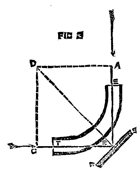
FIG. 3
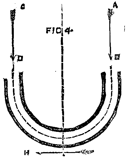
FIG. 4
Table II.—Impact and Reaction in Confined Channels.

-----------------------------+-------+---------+----------+-------
Number of column.            |   1   |    2    |    3     |   4
-----------------------------+-------+---------+----------+-------
Description of experiments.  |Impact.|Reaction.|Resultant.| Angles
                             |       |         |          |  ABS.
-----------------------------+-------+---------+----------+-------
Smooth London tube, 1¾ in.   |  71   |   62    |  94.25   |   49°
  mean radius.               |       |         |          |
                             |       |         |          |
Rough wrought iron tube,     |  78   |   52    |  98.75   |  56.5°
  1¾ in.                     |       |         |          |
                             |       |         |          |
Smooth leaden tube bent to a |  71   |   40    |  81.5    |   60
  sharp right angle.         |       |         |          |
-----------------------------+-------+---------+----------+------
The third column is obtained by constructing a parallelogram of forces, where impact and reaction form the measures of opposing sides, and it furnishes the resultant due to both forces. The fourth column gives the inclination ABS, at which the line of impact must incline toward a plane surface RS, Fig. 3, so as to produce this maximum resultant perpendicularly upon it; as the resultant given in column 3 indicates the full practical effect of impact and reaction. When a stream has its direction changed to one at right angles to its original course, and as such a changed direction is all that can be hoped for by ordinary screw propellers, the figures in column 3 should bear some relationship to such cases. Therefore, it becomes an inquiry of some interest as to what angle of impact has been found best in those screw propellers which have given the best results in practical work. Taking one of the most improved propellers made by the late Mr. Robert Griffiths, its blades do not conform to the lines of a true screw, but it is an oblique paddle, where the acting portions of its blades were set at 48 deg. to the keel of the ship or 42 deg. to the plane of rotation. Again, taking a screw tug boat on the river Thames, with blades of a totally different form to those used by Mr. Griffiths, we still find them set at the same angle, namely, 48 deg. to the keel or 42 deg. to the plane of rotation. An examination of other screws tends only to confirm these figures, and they justify the conclusion that the inclinations of blades found out by practice ought to be arrived at, or at any rate approached, by any sound and reliable theory; and that blades of whatever form must not transgress far from this inclination if they are to develop any considerable efficiency. Indeed, many favorable results obtained by propellers are not due to their peculiarities, but only to the fact that they have been made with an inclination of blade not far from 42 deg. to the plan of rotation. Referring to column 4, and accepting the case of water flowing through a smooth tube as analogous to that of a current flowing within a large body of water, it appears that the inclination necessary to give the highest resultant pressure is an angle of 49 deg., and this corresponds closely enough with the angle which practical constructors of screw propellers have found to give the best results. Until, therefore, we can deal with currents after they have been discharged from the blades of a propeller, it seems unlikely that anything can be done by alterations in the pitch of a propeller. So far as concerns theory, the older turbines were restricted to such imperfect results of impact and reaction as might be obtained by turning a stream at right angles to its original course; and the more scientific of modern turbine constructors may fairly claim credit for an innovation by which practice gave better results than theory seemed to warrant; and the consideration of this aspect of the question will form the concluding subject of the present paper. Referring again to Fig. 3, when a current passes round such a curve as the quadrant of a circle, its horizontal reaction appears as a pressure along c B, which is the result of the natural integration of all the horizontal components of pressures, all of which act perpendicularly to each element of the concave surface along which the current flows. If, now, we add another quadrant of a circle to the curve, and so turn the stream through two right angles, or 180 deg., as shown by Fig. 4, then such a complete reversal of the original direction represents the carrying of it back again to the highest point; it means the entire destruction of its velocity, and it gives the maximum pressure obtainable from a jet of water impinging upon a surface of any form whatsoever. The reaction noticed in Fig. 3 as acting along c B is now confronted by an impact of the now horizontal stream as it is turned round the second 90 deg. of curvature, and reacts also vertically downward. It would almost seem as if the first reaction from B to F should be exactly neutralized by the second impact from F to D. But such is not the case, as experiment shows an excess of the second impact over the first reaction amounting to six units, and shows also that the behavior of the stream through its second quadrant is precisely similar in kind to the first, only less in degree. Also the impact takes place vertically in one case and horizontally in the other. The total downward pressure given by the stream when turned 180 deg. is found by experiment thus: Total impact and reaction from 180 deg. change in direction of current = 132 units; and by deducting the impact 71 units, as previously measured, the new reaction corresponds with an increase of 61 units above the first impact. It also shows an increase of 37.75 units above the greatest resultant obtained by the same stream turned through 90 deg. only. Therefore, in designing a screw propeller or turbine, it would seem from these experiments desirable to aim at changing the direction of the stream, so far as possible, into one at 180 deg. to its original course, and it is by carrying out this view, so far as the necessities of construction will permit, that the scientifically designed modern turbine has attained to that prominence which it holds at present over all hydraulic motors. Much more might be written to extend and amplify the conclusions that can be drawn from the experiments described in the present paper, and from many others made by the writer, but the exigencies of time and your patience alike preclude further consideration of this interesting and important subject.
[1]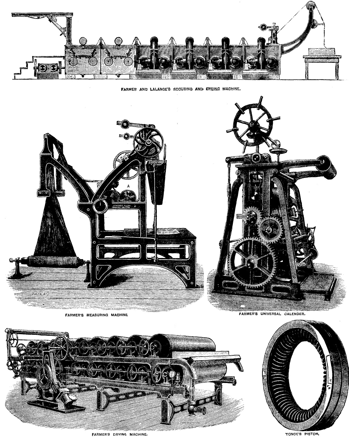
THE TEXTILE EXHIBITION, ISLINGTON.
In the recent textile exhibition at Islington, one of the most extensive exhibits was that, of Messrs. James Farmer and Sons, of Salford. The exhibit consists of a Universal calender, drying machines, patent creasing, measuring, and marking machines, and apparatus for bleaching, washing, chloring, scouring, soaping, dunging, and dyeing woven fabrics. The purpose of the Universal calender is, says the Engineer, to enable limited quantities of goods to be finished in various ways without requiring different machines. The machine consists of suitable framing, to which is attached all the requisite stave rails, batching apparatus, compound levers, top and bottom adjusting screws, and level setting down gear, also Stanley roller with all its adjustments. It is furthermore supplied with chasing arrangement and four bowls; the bottom one is of cast iron, with wrought iron center; the next is of paper or cotton; the third of chilled iron fitted for heating by steam or gas, and the top of paper or cotton. By this machine are given such finishes as are known as "chasing finish" when the thready surface is wanted; "frictioning," or what is termed "glazing finish," "swigging finish," and "embossing finish;" the later is done by substituting a steel or copper engraved roller in place of the friction bowl. This machine is also made to I produce the "Moire luster" finish. The drying machine consists of nineteen cylinders, arranged with stave rails and plaiting down apparatus. These cylinders are driven by bevel wheels, so that each one is independent of its neighbor, and should any accident occur to one or more of the cylinders or wheels, the remaining ones can be run until a favorable opportunity arrives to repair the damage. A small separate double cylinder diagonal engine is fitted to this machine, the speed of which can be adjusted for any texture of cloth, and being of the design it is, will start at once on steam being turned one. The machine cylinders are rolled by a special machine for that purpose, and are perfectly true on the face. Their insides are fitted with patent buckets, which remove all the condensed water. In the machine exhibited, which is designed for the bleaching, washing, chloring, and dyeing, the cloth is supported by hollow metallic cylinders perforated with holes and corrugated to allow the liquor used to pass freely through as much of the cloth as possible; the open ends of the cylinders are so arranged that nearly all of their area is open to the action of the pump. The liquor, which is drawn through the cloth into the inside of the cylinders by the centrifugal pumps, is discharged back into the cistern by a specially constructed discharge pipe, so devised that the liquor, which is sent into it with great force by the pump, is diverted so as to pour straight down in order to prevent any eddies which could cause the cloth to wander from its course. The cloth is supported to and from the cylinders by flat perforated plates in such a manner that the force of the liquor cannot bag or displace the threads of the cloth, and by this means also the liquor has a further tendency to penetrate the fibers of the cloth. Means are provided for readily and expeditiously cleansing the entire machine. The next machine which we have to notice in this exhibit is Farmer's patent marking and measuring machine, the purpose of which is to stamp on the cloths the lengths of the same at regular distances. It is very desirable that drapers should have some simple means of discovering at a glance what amount of material they have in stock without the necessity of unrolling their cloth to measure it, and this machine seems to perfectly meet the demands of the case. The arrangement for effecting the printing and inking is shown in our engraving at A. It is contained within a small disk, which can be moved at will, so that it can be adapted to various widths of cloth or other material. A measuring roller runs beside the printing disk, and on this is stamped the required figures by a simple contrivance at the desired distances, say every five yards. The types are linked together into a roller chain which is carried by the disk, A, and they ink themselves automatically from a flannel pad. The machine works in this way: The end of the piece to be measured is brought down until it touches the surface of the table, the marker is turned to zero, and also the finger of the dial on the end of the measuring roller. The machine is then started, and the lengths are printed at the required distances until it becomes necessary to cut out the first piecing or joint in the fabric. The dial registers the total length of the piece.
In the North of England Report, the endless rope systems are classified as No. 1 and No 2 systems. No. 1, which has the rope under the tubs, is said to be in operation in the Midland counties. To give motion to the rope a single wheel is used, and friction for driving the rope is supplied either by clip pulleys or by taking the rope over several wheels. The diagram shows an arrangement for a tightening arrangement. One driving wheel is used, says The Colliery Guardian, and the rope is kept constantly tight by passing it round a pulley fixed upon a tram to which a heavy weight is attached. Either one or two lines of rails are used. When a single line is adopted the rope works backward and forward, only one part being on the wagon way and the other running by the side of the way. When two lines are used the ropes move always in one direction, the full tubs coming out on one line and the empties going in on the other. The rope passes under the tubs, and the connection is made by means of a clamp or by sockets in the rope, to which the set is attached by a short chain. The rope runs at a moderately high speed.
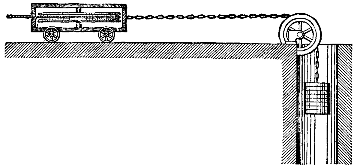
TIGHTENING ARRANGEMENT—ENDLESS ROPE HAULAGE.
No. 2 system was peculiar to Wigan. A double line of rails is always used. The rope rests upon the tubs, which are attached to the rope either singly or in sets varying in number from two to twelve. The other engraving shows a mode of connection between the tubs and the rope by a rope loop as shown.
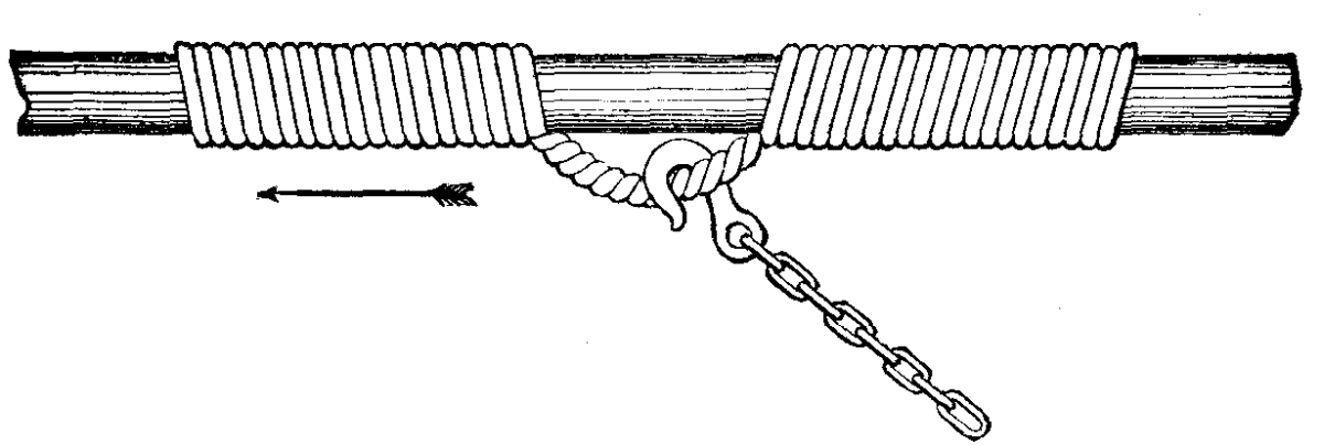
ATTACHMENT TO ENDLESS ROPE "OVER."
The tubs are placed at a regular distance apart, and the rope works slowly. Motion is given to the rope by large driving pulleys, and friction is obtained by taking the rope several times round the driving pulley.
Opinions are so firmly fixed at present that water is capable of carrying the germs of disease that, in cases of epidemics, the recommendation is made to drink natural mineral waters, or to boil ordinary water. This is a wise measure, assuredly; but mineral waters are expensive, and, moreover, many persons cannot get used to them. As for boiled water, that is a beverage which has no longer a normal composition; a portion of its salts has become precipitated, and its dissolved gases have been given off. In spite of the aeration that it is afterward made to undergo, it preserves an insipid taste, and I believe that it is not very digestible. I have thought, then, that it would be important, from a hygienic standpoint, to have a filter that should effectually rid water of all the microbes or germs that it contains, while at the same time preserving the salts or gases that it holds in solution. I have reached such a result, and, although it is always delicate to speak of things that one has himself done, I think the question is too important to allow me to hold back my opinion in regard to the apparatus. It is a question of general hygiene before which my own personality must disappear completely.
In Mr. Pasteur's laboratory, we filter the liquids in which microbes have been cultivated, so as to separate them from the medium in which they exist. For this purpose we employ a small unglazed porcelain tube that we have had especially constructed therefor. The liquid traverses the porous sides of this under the influence of atmospheric pressure, since we cause a vacuum around the tube by means of an air-pump. We collect in this way, after several hours, a few cubic inches of a liquid which is absolutely pure, since animals may be inoculated with it without danger to them, while the smallest quantity of the same liquid, when not filtered, infallibly causes death.
This is the process that I have applied to the filtration of water. I have introduced into it merely such modifications as are necessary to render the apparatus entirely practical. My apparatus consists of an unglazed porcelain tube inverted upon a ring of enameled porcelain, forming a part thereof, and provided with an aperture for the outflow of the liquid. This tube is placed within a metallic one, which is directly attached to a cock that is soldered to the service pipe. A nut at the base that can be maneuvered by hand permits, through the intermedium of a rubber washer resting upon the enameled ring, of the tube being hermetically closed.
Under these circumstances, when the cock is turned on, the water fills the space between the two tubes and slowly filters, under the influence of pressure, through the sides of the porous one, and is freed from all solid matter, including the microbes and germs, that it contains. It flows out thoroughly purified, through the lower aperture, into a vessel placed there to receive it.
I have directly ascertained that water thus filtered is deprived of all its germs. For this purpose I have added some of it (with the necessary precautions against introducing foreign organisms) to very changeable liquids, such as veal broth, blood, and milk, and have found that there was no alteration. Such water, then, is incapable of transmitting the germs of disease.
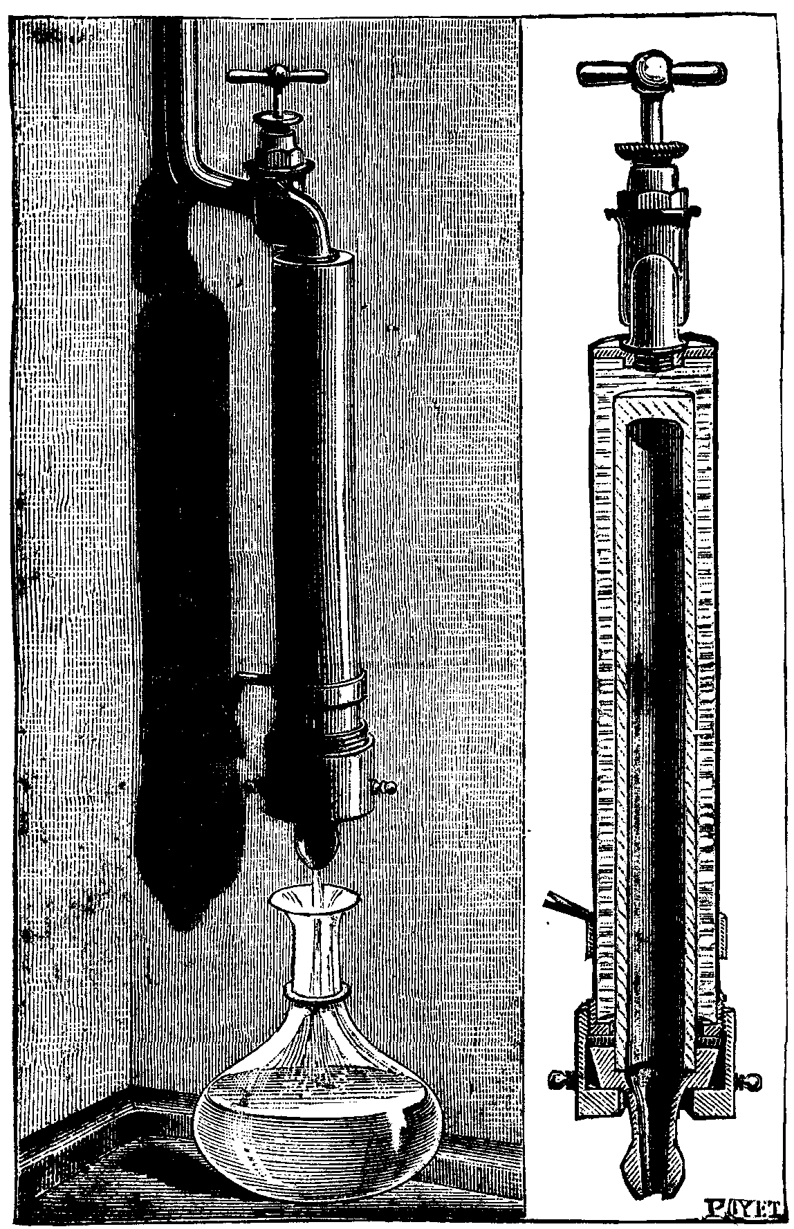
CHAMBERLAND'S WATER FILTER.
With an apparatus like the one here figured, and in which the filtering tube is eight inches in length by about one inch in diameter, about four and a half gallons of water per day may be obtained when the pressure is two atmospheres—the mean pressure in Mr. Pasteur's laboratory, where my experiments were made. Naturally, the discharge is greater or less according to the pressure. A discharge of three and a half to four and a half gallons of water seems to me to be sufficient for the needs of an ordinary household. For schools, hospitals, barracks, etc., it is easy to obtain the necessary volume of water by associating the tubes in series. The discharge will be multiplied by the number of tubes.
In the country, or in towns that have no water mains, it will be easy to devise an arrangement for giving the necessary pressure. An increase in the porosity of the filtering tube is not to be thought of, as this would allow very small germs to pass. This filter being a perfect one, we must expect to see it soil quickly. Filters that do not get foul are just the ones that do not filter. But with the arrangement that I have adopted the solid matters deposit upon the external surface of the filter, while the inner surface always remains perfectly clean. In order to clean the tube, it is only necessary to take it out and wash it vigorously. As the tube is entirely of porcelain, it may likewise be plunged into boiling water so as to destroy the germs that may have entered the sides or, better yet, it may be heated over a gas burner or in an ordinary oven. In this way all the organic matter will be burned, and the tube will resume its former porosity.—M. Chamberland, La Nature.
The alchemists dreamed and talked of that universal solvent which they so long and vainly endeavored to discover; still, for all this, not only the alchemist of old, but his more immediate successor, the chemist of to-day, has found no solvent so universal as water. No liquid has nearly so wide a range of dissolving powers, and, taking things all round, no liquid exercises so slight an action upon the bodies dissolved—evaporate the water away, and the dissolved substance is obtained in an unchanged condition; at any rate, this is the general rule.
The function of water in nature is essentially that of a solvent or a medium of circulation; it is not, in any sense, a food, yet without it no food can be assimilated by an animal. Without water the solid materials of the globe would be unable to come together so closely as to interchange their elements; and unless the temperatures were sufficiently high to establish an igneous fluidity, such as undoubtedly exists in the sun, there would be no circulation of matter to speak of, and the earth would be, as it were, locked up or dead.
When we look upon water as the nearest approach to a universal solvent that even the astute scientist of to-day has been able to discover, who can wonder that it is never found absolutely pure in nature? For wherever it accumulates it dissolves something from its surroundings. Still, in a rain-drop just formed we have very nearly pure water; but even this contains dissolved air to the extent of about one-fiftieth of its volume, and as the drop falls downward it takes up such impurities as may be floating in the atmosphere; so that if our rain-drop is falling immediately after a long drought, it becomes charged with nitrate or nitrite of ammonia and various organic matters—perhaps also the spores or germs of disease. Thus it will be seen that rain tends to wonderfully clear or wash the atmosphere, and we all know how much a first rain is appreciated as an air purifier, and how it carries down with it valuable food for plants. The rain-water, in percolating through or over the land, flows mainly toward the rivers, and in doing so it becomes more or less charged with mineral matter, lime salts and common salt being the chief of them; while some of that water which has penetrated more deeply into the earth takes up far more solid matter than is ordinarily found in river water. The bulk of this more or less impure water tends toward the ocean, taking with it its load of salt and lime. Constant evaporation, of course, takes place from the surface of the sea, so that the salt and lime accumulate, this latter being, however, ultimately deposited as shells, coral, and chalk, while nearly pure or naturally distilled water once more condenses in the form of clouds. This process, by which a constant supply of purified water is kept up in the natural economy, is imitated on a small scale when water is converted into steam by the action of heat, and this vapor is cooled so as to reproduce liquid water, the operation in question being known as distillation.
For this purpose an apparatus known as a still is required; and although by law one must pay an annual license fee for the right to use a still, it is not usual for the government authorities to enforce the law when a still is merely used for purifying water.
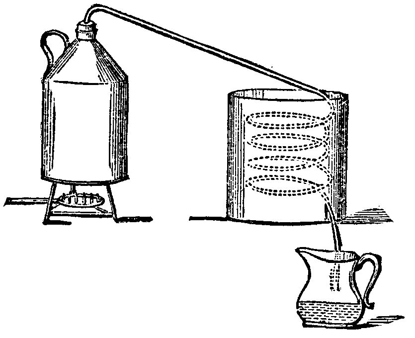
One of the best forms of still for the photographer to employ consists of a tin can or bottle in which the water is boiled, and to this a tin tube is adapted by means of a cork, one end of this tin tube terminating in a coil passing through a tub or other vessel of cold water. A gas burner, as shown, is a convenient source of heat, and in order to insure a complete condensation of the vapor, the water in the cooling tub must be changed now and again.
Sometimes the vapor is condensed by being allowed to play against the inside of a conical cover which is adapted to a saucepan, and is kept cool by the external application of cold water; and in this case the still takes the form represented by the subjoined diagrams; such compact and portable stills being largely employed in Ireland for the private manufacture of whisky.
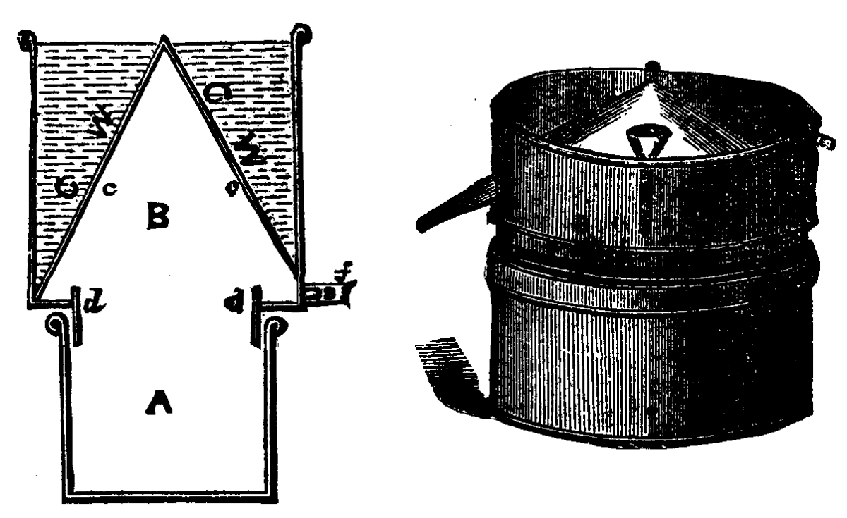
It is scarcely necessary to say that the condensed water trickles down on the inside of the cone, and flows out at the spout.
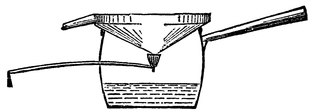
An extemporized arrangement of a similar character may be made by passing a tobacco pipe through the side of a tin saucepan as shown below, and inverting the lid of the saucepan; if the lid is now kept cool by frequent changes of water inside it, and the pipe is properly adjusted so as to catch the drippings from the convex side of the lid, a considerable quantity of distilled water may be collected in an hour or so.
The proportion of solid impurities present in water as ordinarily met with is extremely variable: rain water which has been collected toward the end of a storm contains only a minute fraction of a grain per gallon, while river or spring water may contain from less than thirty grains per gallon or so and upward. Ordinary sea water generally contains from three to four per cent. of saline matter, but that of the Dead Sea contains nearly one-fourth of its weight of salts.
The three impurities of water which most interest the photographer are lime or magnesia salts, which give the so-called hardness; chlorides (as, for example, chloride of sodium or common salt), which throw down silver salts; and organic matter, which may overturn the balance of photographic operations by causing premature reduction of the sensitive silver compounds. To test for them is easy. Hardness is easily recognizable by washing one's hands in the water, the soap being curdled; but in many cases one must rather seek for a hard water than avoid it, as the tendency of gelatine plates to frill is far less in hard water than in soft water. It is, indeed, a common and useful practice to harden the water used for washing by adding half an ounce or an ounce of Epsom salts (sulphate of magnesia) to each bucket of water. Chlorides—chloride of sodium or common salt being that usually met with—may be detected by adding a drop or two of nitrate of silver to half a wineglassful of the water, a few drops of nitric acid being then added. A slight cloudiness indicates a trace of chlorides, and a decided milkiness shows the presence of a larger quantity. If it is wished to get a somewhat more definite idea of the amount, it is easy to make up a series of standards for comparison, by dissolving known weights of common salt in distilled or rain water, and testing samples of them side by side with the water to be examined.
Organic matters may be detected by adding a little nitrate of silver to the water, filtering off from any precipitate of chloride of silver, and exposing the clear liquid to sunlight; a clean stoppered bottle being the most convenient vessel to use. The extent to which a blackening takes place may be regarded as approximately proportionate to the amount of organic matter present.
Filtration on a small scale is not altogether a satisfactory mode of purifying water, as organic impurities often accumulate in the filter, and enter into active putrefaction when hot weather sets in.—Photo. News.
According to the London Mining Journal, Mr. W.E. Garforth, of Normanton, has introduced an ingenious invention, the object of which is to detect fire-damp in collieries with the least possible degree of risk to those engaged in the work. Mr. Garforth's invention, which is illustrated in the diagram given below, consists in the use of a small India rubber hand ball, without a valve of any description; but by the ordinary action of compressing the ball, and then allowing it to expand, a sample of the suspected atmosphere is drawn from the roof, or any part of the mine, without the great risk which now attends the operation of testing for gas should the gauze of the lamp be defective. The sample thus obtained is then forced through a small protected tube on to the flame, when if gas is present it is shown by the well-known blue cap and elongated flame. From this description, and from the fact that the ball is so small that it can be carried in the coat pocket, or, if necessary, in the waistcoat pocket, it will be apparent what a valuable adjunct Mr. Garforth's invention will prove to the safety-lamp. It has been supposed by some persons that explosions have been caused by the fire-trier himself, but owing to his own death in most cases the cause has remained undiscovered. This danger will now be altogether avoided. It is well known that the favorite form of lamp with the firemen is the Davy, because it shows more readily the presence of small quantities of gas; but the Davy was some years ago condemned, and is now strictly prohibited in all Belgian and many English mines. Recent experience, gained by repeated experiments with costly apparatus, has resulted in not only proving the Davy and some other descriptions of lamps to be unsafe, but some of our Government Inspectors and our most experienced mining engineers go so far as to say that "no lamp in a strong current of explosive gas is safe unless protected by a tin shield."

If such is the case, Mr. Garforth seems to have struck the key-note when, in the recent paper read before the Midland Institute of Mining and Civil Engineers, and which we have now before us, he says: "It would seem from the foregoing remarks that in any existing safety-lamp where one qualification is increased another is proportionately reduced; so it is doubtful whether all the necessary requirements of sensitiveness, resistance to strong currents, satisfactory light, self-extinction, perfect combustion, etc., can ever be combined in one lamp."
The nearest approach to Mr. Garforth's invention which we have ever heard of is that of a workman at a colliery in the north of England, who, more than twenty years ago, to avoid the trouble of getting to the highest part of the roof, used a kind of air pump, seven or eight feet long, to extract the gas from the breaks; and some five years ago Mr. Jones, of Ebbw Vale, had a similar idea. It appears that these appliances were so cumbersome, besides requiring too great length or height for most mines, and necessitating the use of both hands, that they did not come into general use. The ideas, however, are totally different, and the causes which have most likely led to the invention of the ball and protected tube were probably never thought of until recently; indeed, Mr. Garforth writes that he has only learned about them since his paper was read before the Midland Institute, and some weeks after his patent was taken out.
No one, says Mr. Garforth, in his paper read before the Midland Institute, will, I presume, deny that the Davy is more sensitive than the tin shield lamp, inasmuch as in the former the surrounding atmosphere or explosive mixture has only one thickness of gauze to pass through, and that on a level with the flame; while the latter has a number of small holes and two or three thicknesses of gauze (according to the construction of the lamp), which the gas must penetrate before it reaches the flame. Moreover, the tin shield lamp, when inclined to one side, is extinguished (though not so easily as the Mueseler); and as the inlet holes are 6 inches from the top, it does not show a thin stratum of fire-damp near the roof as perceptibly as the Davy, which admits of being put in almost a horizontal position. Although the Davy lamp was, nearly fifty years ago, pronounced unsafe, by reason of its inability to resist an ordinary velocity of eight feet per second, yet it is still kept in use on account of its sensitiveness. Its advocates maintain that a mine can be kept safer by using the Davy, which detects small quantities of gas, and thereby shows the real state of the mine, than by a lamp which, though able to resist a greater velocity, is not so sensitive, and consequently is apt to deceive. Assuming the Davy lamp to be condemned (as it has already been in Belgium and in some English mines), the Stephenson and some of the more recently invented lamps pronounced unsafe, then if greater shielding is recommended the question is, what means have we for detecting small quantities of fire-damp?
It would seem from the foregoing remarks that in any existing safety-lamp, where one qualification is increased another is proportionately reduced; so it is doubtful whether all the necessary requirements of sensitiveness, resistance to strong currents, satisfactory light, self-extinction, perfect combustion, etc., can ever be combined in one lamp. The object of the present paper is to show that with the assistance of the fire-damp detecter, the tin shield, or any other description of lamp, is made as sensitive as the Davy, while its other advantages of resisting velocity, etc., are not in any way interfered with. As a proof of this I may mention that a deputy of experience recently visited a working place to make his inspection. He reported the stall to be free from gas, but when the manager and steward visited it with the detecter, which they applied to the roof (where it would have been difficult to put even a small Davy), it drew a sample of the atmosphere which, on being put to the test tube in the tin-shield lamp, at once showed the presence of fire-damp. Out of twenty-eight tests in a mine working a long-wall face the Davy showed gas only eleven times, while the detecter showed it in every case. The detecter, as will be perceived from the one exhibited, and the accompanying sectional drawing, consists simply of an oval-shaped India rubber ball, fitted with a mouthpiece. The diameter is about 2¼ inches by 3 inches, its weight is two ounces, and it is so small that it can be carried without any inconvenience in the coat or even in the waistcoat pocket. Its capacity is such that all the air within it may be expelled by the compression of one hand.
The mouthpiece is made to fit a tube in the bottom of the lamp, and when pressed against the India rubber ring on the ball-flange, a perfectly tight joint is made, which prevents the admission of any external air. The tube in the bottom of the lamp is carried within a short distance of the height of the wick-holder. It is covered at the upper end with gauze, besides being fitted with other thicknesses of gauze at certain distances within the tube; and if it be found desirable to further protect the flame against strong currents of air, a small valve may be placed at the inlet, as shown in the drawing. This valve is made of sufficient weight to resist the force of a strong current, and is only lifted from its seat by the pressure of the hand on the mouthpiece. It will be apparent from the small size and elasticity of the detecter that the test can easily be made with one hand, and when the ball is allowed to expand a vacuum is formed within it, and a sample of the atmosphere drawn from the breaks, cavities, or highest parts of the roof, or, of course, any portion of the mine. When the sample is forced through the tube near the flame, gas if present at once reveals itself by the elongation of the flame in the usual way, at the same time giving an additional proof by burning with a blue flame on the top of the test tube. If gas is not present, the distinction is easily seen by the flame keeping the same size, but burning with somewhat greater brightness, owing to the increased quality of oxygen forced upon it.
I venture to claim for this method of detecting fire-damp among other advantages: 1. The detecter, on account of its size, can be placed in a break in the roof where an ordinary lamp—even a small Davy—could not be put, and a purer sample of the suspected atmosphere is obtained than would be the case even a few inches below the level of the roof, 2. The obtaining and testing of a sample in the manner above described takes away the possibility of an explosion, which might be the result if a lamp with a defective gauze were placed in an explosive atmosphere. No one knows how many explosions have not been caused by the fire-trier himself. This will now be avoided. (Although lamps fitted with a tin shield will be subjected to the same strict examination as hitherto, still they do not admit of the same frequent inspection as those without shields, for in the latter case each workman can examine his own lamp as an extra precaution; whereas the examination of the tin shield lamps will rest entirely with the lamp man.) 3. The lamp can be kept in a pure atmosphere while the sample is obtained by the detecter, and at a greater height than the flame in a safety-lamp could be properly distinguished. The test can afterward be made in a safe place, at some distance from the explosive atmosphere; and, owing to the vacuum formed, the ball (without closing the mouthpiece) has been carried a mile or more without the gas escaping. 4. The detecter supplies a better knowledge of the condition of the working places, especially in breaks and cavities in the roof; which latter, with the help of a nozzle and staff, may be reached to a height of ten feet or more, by the detecter being pressed against the roof and sides, or by the use of a special form of detecter. 5. Being able at will to force the contents of the detecter on to the flame, the effects of an explosion inside the lamp need not be feared. (This danger being removed, admits, I think, of the glass cylinder being made of a larger diameter, whereby a better light is obtained; it may also be considered quite as strong, when used with the detecter, as a lamp with a small diameter, when the latter is placed in an explosive atmosphere.) 6. The use of the detecter will permit the further protection of the present tin shield lamp, by an extra thickness of gauze, if such addition is found advantageous in resisting an increased velocity. 7. In the Mueseler, Stephenson, and other lamps, where the flame is surrounded by glass, there is no means of using the wire for shot firing. The detecter tube, although protected by two thicknesses of gauze, admits of this being done by the use of a special form of valve turned by the mouthpiece of the detecter. The system of firing shots or using open lamps in the same pit where safety lamps are used is exceedingly objectionable; still, under certain conditions shots may be fired without danger. Whether safety lamps or candles are used, it is thought the use of the detecter will afford such a ready means of testing that more examinations will be made before firing a shot, thereby insuring greater safety. 8. In testing for gas with a safety lamp there is a fear of the light being extinguished, when the lamp is suddenly placed in a quantity of gas, or in endeavoring to get a very small light; this is especially the case with some kinds of lamps. With the detecter this is avoided, as a large flame can be used, which is considered by some a preferable means of testing for small quantities; and the test can be made without risk. Where gas is present in large quantities, the blue flame at the end of the test tube will be found a further proof. This latter result is produced by the slightest compression of the ball. (I need not point out the inconvenience and loss of time in having to travel a mile or more to relight.) As regards the use of the detecter with open lights, several of the foregoing advantages or modifications of them will apply. Instead of having to use the safety lamp as at present, it is thought that the working place will be more frequently examined, for a sample of the suspected atmosphere can be carried to a safe place and forced on to the naked light, when, if gas be present, it simply burns at the end of the mouthpiece like an ordinary gas jet. There are other advantages, such as examining the return airways without exposing the lamp, etc., which will be apparent, and become of more or less importance according to the conditions under which the tests are made.
In conclusion, I wish to paint out that the practice adopted at some collieries, of having all the men supplied with the most approved lamp (such as the Mueseler or tin shield lamp) is not a safe one. If the strength of a chain is only equal to the weakest link, it may be argued that the safety of a mine is only equal to that of the most careless man or most unsafe lamp in it. If, therefore, the deputies, whose duty it is to look for gas and travel the most dangerous parts of the mine, are obliged to use the Davy on account of its sensitiveness, may it not be said that, as their lamps are exposed equally with the workmen's to the high velocities of air, they are the weak links in the safety of the mine? For the reasons given, I venture to submit that the difficulties and dangers I have mentioned will be largely reduced, if not wholly overcome, by the use of the fire-damp detecter.
In computing the weight of the various items for a photographic tour, the glass almost invariably comes out at the head of the list, and the farther or longer the journey, so much more does the weight of the plates stand out pre-eminent; indeed, if one goes out on a trip with only three dozen half-plates, the glass will probably weigh nearly as much as camera, backs, and tripod, in spite of the stipulation with the maker to supply plates on "thin glass."
Next in importance to glass as a support comes paper, and it is quite easy to understand that the tourist in out of the way parts might be able to take an apparatus containing a roll of sensitive paper, when it would be altogether impracticable for him to take an equivalent surface of coated glass, and in such a case the roller slide becomes of especial value.
The roller slide of Melhuish is tolerably well known, and is, we believe, now obtainable as an article of commerce. The slide is fitted up with two rollers, a a, and the sensitive sheets, b b, are gummed together, making one long band, the ends of which are gummed to pieces of paper always kept on the rollers. The sensitive sheets are wound off the left or reserve roller on to the right or exposed roller, until all are exposed.
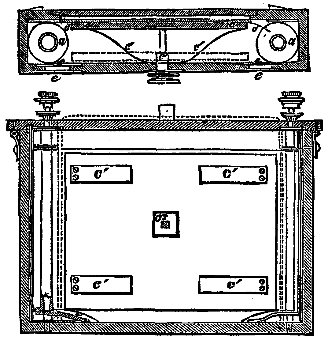
The rollers are supported on springs, a¹ a¹, to render their motion equal; they are turned by the milled heads, m m, and clamped when each fresh sheet is brought into position by the nuts, a² a². c, is a board which is pressed forward by springs, c¹ c¹, so as to hold the sheet to be exposed, and keep it smooth against the plate of glass, d; when the sheet has been exposed, the board is drawn back from the glass in order to release the exposed sheet, and allow it to be rolled on the exposed roller; the board is kept back while this is being done by turning the square rod, c², half round, so that the angles of the square will not pass back through the square opening until again turned opposite to it; e e are doors, by opening which the operator can see (through the yellow glass, y y) to adjust the position of the sensitive sheets when changing them.
The remarkable similarity of such a slide to the automatic printing-frame described last week will strike the reader; and, like the printing-frame, it possesses the advantage of speed in working—no small consideration to the photographer in a distant, and possibly hostile, country.
Fine paper well sized with an insoluble size and coated with a sensitive emulsion is, we believe, the very best material to use in the roller slide; and such a paper might be made in long lengths at a very low price, a coating machine similar to that constructed for use in making carbon tissue being employed. We have used such paper with success, and hope that some manufacturer will introduce it into commerce before long. But the question suggests itself, how are the paper negatives to be rendered transparent, and how is the grain of the paper to be obliterated? Simply by pressure, as extremely heavy rolling will render such paper almost as transparent as glass, a fact abundantly demonstrated by Mr. Woodbury in his experiments on the Photo-Filigrane process, and confirmed by some trials which we have made.
It must be confessed that roller slide experiments which we have made with sensitive films supported on gelatine sheets, or on such composite sheets as the alternate rubber and collodion pellicle of Mr. Warnerke, have been hardly satisfactory—possibly, however, from our own want of skill; while no form of the Calotype process which we have tried has proved so satisfactory as gelatino-bromide paper.—Photo. News.
M. Audra, in the name of M. Braun, of Angoulême, has presented to the Photo Society of France a new instantaneous shutter. The shutter is formed by a revolving metallic disk out of which a segment has been taken. This disk is placed in the center of the diaphragms, in order to obtain the greatest rapidity combined with the least possible distance to travel. On the axis to which this circular disk is fixed is a small wheel, to which is attached a piece of string, and when the disk is turned round for the exposure the string is wound round the wheel. If the string be pulled, naturally the disk will revolve back to its former position so much the more quickly the more violently the string is pulled. M. Braun has replaced the hand by a steel spring attached to the drum of the lens (Fig. 2) By shortening or lengthening the string, more or less rapid exposures may be obtained.
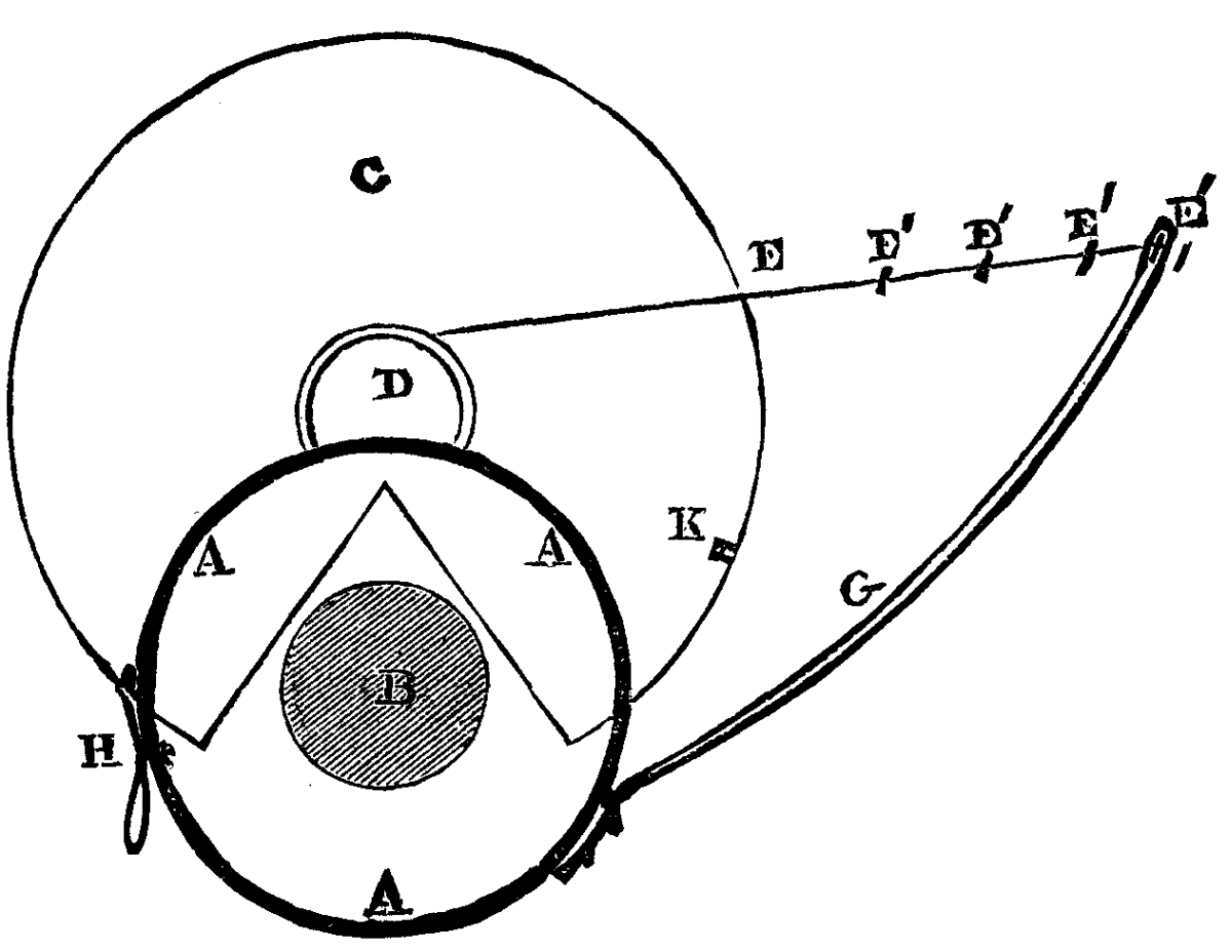
AAA, lens; B, aperture of lens; C, metallic disk; D, wheel on the axis; E, cord or string; E¹E¹E¹E¹, knots in string; G, steel spring; H, catch; K, socket for catch.
Within a short period sulphurous acid has become an important element in the preparation of an excellent pyro developer for gelatine plates; and as it is more or less unstable in its keeping qualities, some easy method of preparing a small quantity which shall have a uniform strength is desirable. A method recently described in the Photographic News will afford the amateur photographer a ready way of preparing a small quantity of the acid.
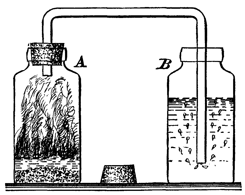
In the illustration given above, A and B are two bottles, both of which can be closed tightly with corks. A hole is made in the cork in the bottle, A, a little smaller than the glass tube which connects A and B. It is filed out with a rat-tail file until it is large enough to admit the tube very tightly. The tube may be bent easily, by being heated over a common fish-tail gas burner or over the top of the chimney of a kerosene lamp, so as to form two right angles, one end extending close to the bottom of the bottle B as shown.
Having fitted up the apparatus, about two ounces of hyposulphite of soda are placed in the bottle A, while the bottle B is about three-fourths filled with water—distilled or melted ice water is to be preferred; some sulphuric acid—about two ounces—is now diluted with about twice its bulk of water, by first putting the water into a dish and pouring in the acid in a steady stream, stirring meanwhile. It is well to set the dish in a sink, to avoid any damage which might occur through the breaking of the dish by the heat produced; when cool, the solution is ready for use and may be kept in a bottle.
The cork which serves to adapt the bent tube to the bottle A is now just removed for an instant, the other end remaining in the water in bottle B, and about two or three ounces of the dilute acid are poured in upon the hyposulphite, after which the cork is immediately replaced.
Sulphurous acid is now evolved by the action of the acid on the hypo, and as the gas is generated it is led as a series of bubbles through the water in the bottle B as shown. The air space above the water in bottle B soon becomes filled by displacement with sulphurous acid gas, which is a little over twice as heavy as air; so in order to expedite the complete saturation of the water, it is convenient to remove the bottle A with its tube from bottle B, and after having closed the latter by its cork or stopper, to agitate it thoroughly by turning the bottle upside down. As the sulphurous acid gas accumulated in the air space over the water is absorbed by the water, a partial vacuum is created, and when the stopper is eased an inrush of air may be noted. When, after passing fresh gas through the liquid for some minutes, no further inrush of air is noted on easing the stopper as before described after agitating the bottle, it may be concluded that the water is thoroughly saturated with sulphurous acid and is strong enough for immediate use. More gas can be generated by adding more dilute sulphuric acid to the hypo until the latter is decomposed; then it should be thrown aside, and a fresh charge put in the bottle. On preparing the solution it is well to set the bottles on the outside ledge of the window, or in some other open situation where no inconvenience will result from the escape of the excess of sulphurous gas as it bubbles through the water.
The solution of sulphurous acid, if preserved at all, ought to be kept in small bottles, completely filled and perfectly closed; but as it is very easy to saturate a considerable quantity of water with sulphurous acid gas in a short time, there is but little inducement to use a solution which may possibly have become weakened by keeping.
Care should be taken not to add too much dilute acid to the hypo at a time, else excessive effervescence will occur, and the solution will froth over the top of the bottle.
About three years ago the Italian Government invited the architects and artists of the world to furnish competitive designs for a national monument to be erected to the memory of King Victor Emanuel II. at Rome. More than $1,800,000 were appropriated for the monument exclusive of the foundation. It is very seldom that an artist has occasion to carry out as grand and interesting a work as this was to be: the representation of the creator of the Italian union in the new capitol of the new state surrounded by the ruins and mementos of a proud and mighty past. Prizes of $10,000, $6,000, and $4,000 were donated for the first, second, and third prize designs respectively. Designs were entered, not only from Italy, but also from Germany, France, Norway, Sweden, England, and America, and even from Caucasus and Japan.
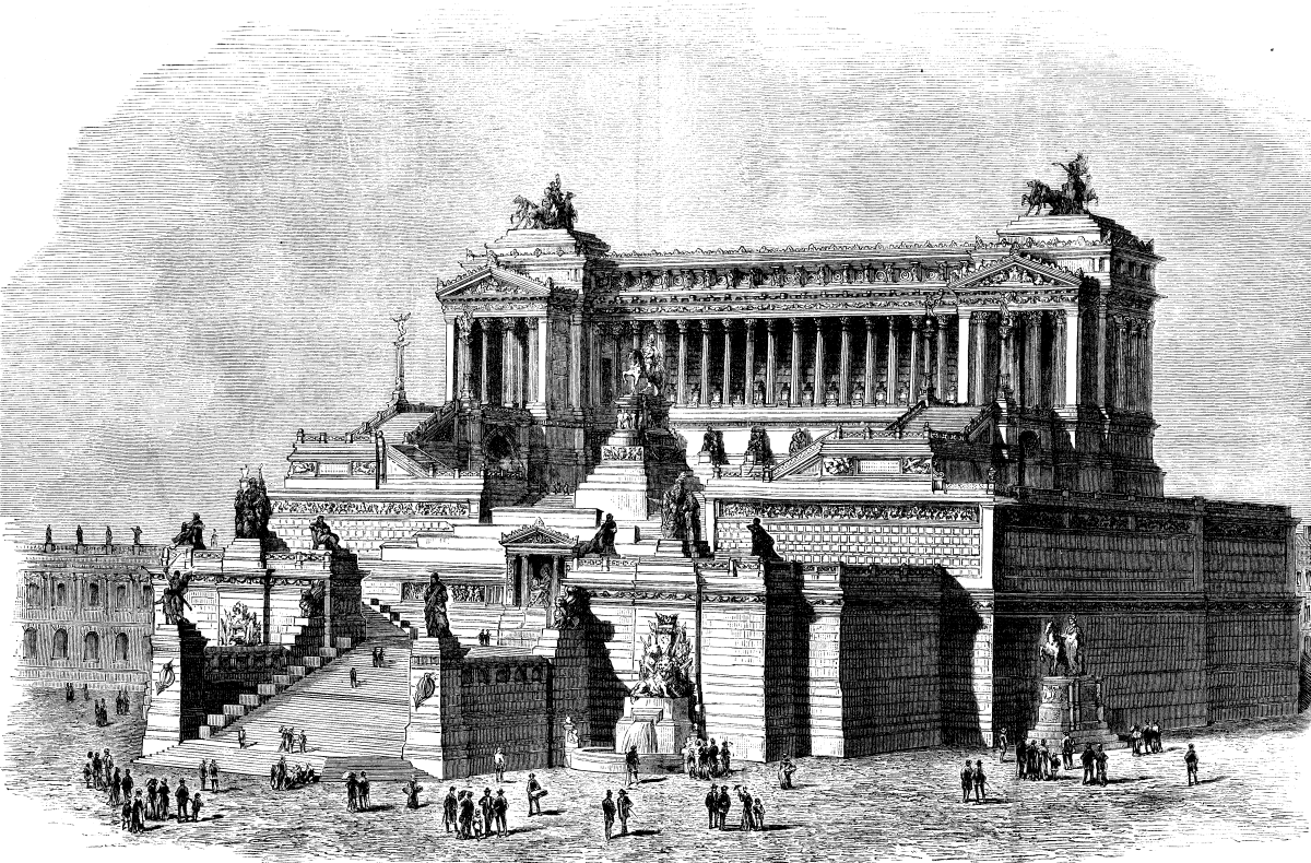
THE UNION OF ITALY. SACCONI'S PRIZE DESIGN FOR THE NATIONAL MONUMENT, ROME, ITALY.
The height and size of the monument were not determined on, nor was the exact location, and the competitors had full liberty in relation to the artistic character of the monument, and it was left for them to decide whether it should be a triumphal arch, a column, a temple, a mausoleum, or any other elaborate design. This great liberty given to the competitors was of great value and service to the monument commission, as it enabled them to decide readily what the character of the monument should be but it was a dangerous point for the artists, at which most of them foundered. The competition was resultless. Two prizes were given, but new designs had to be called for, which were governed more or less by a certain programme issued by the committee.
In place of the Piazza de Termini, a square extending from the church of St. Maria degli Angeli to the new Via Nazionale, to which preference was given by the competitors, the heights of Aracoeli were chosen. The monument was to be erected at this historic place in front of the side wall of the church, with the center toward the Corso, high above the surrounding buildings. The programme called for an equestrian statue of the King located in front of an architectural background which was to cover the old church walls, and was to be reached by a grand staircase.
Even the result of this second competition was not definite, but as the designers were guided by the programme, the results obtained were much more satisfactory. The commission decided not to award the first prize, but honored the Italian architects Giuseppi Sacconi and Manfredo Manfredi, and the German Bruno Schmitz, with a prize of $2,000 each; and requested them to enter into another competition and deliver their models within four months, so as to enable the commission to come to a final decision. On June 18, the commission decided to accept Sacconi's design for execution, and awarded a second prize of $2,000 to Manfredi.
Sacconi's design, shown opposite page, cut taken from the Illustrirte Zeitung, needs but little explanation. An elegant gallery of sixteen Corinthian columns on a high, prominent base is crowned by a high attica and flanked by pavilions. It forms the architectural background for the equestrian statue, and is reached by an elaborately ornamented staircase.
Manfredi's design shows a handsomely decorated wall in place of the gallery, and in front of the wall an amphitheater is arranged, in the center of which the equestrian statue is placed. Bruno Schmitz' design shows a rich mosaic base supporting an Ionic portico, from the middle of which a six column Corinthian "pronaos" projects, which no doubt would have produced a magnificent effect in the streets of Rome.
The statement that modern culture can be understood only through a study of all its stages of development is equally true of its several branches.
Let us assume that decorative art is one of these. It contains in itself, like language and writing, elements of ancient and even of prehistoric forms, but it must, like these other expressions of culture, which are forever undergoing changes, adapt itself to the new demands which are made upon it, not excepting the very arbitrary ones of fashion; and it is owing to this cause that, sometimes even in the early stages of its development, little or nothing of its original form is recognizable. Investigations the object of which is to clear up this process of development as far as possible are likely to be of some service; a person is more likely to recognize the beauties in the details of ornamental works of art if he has an acquaintance with the leading styles, and the artist who is freed from the bondage of absolute tradition will be put into a better position to discriminate between accidental and arbitrary and organic and legitimate forms, and will thus have his work in the creation of new ones made more easy for him.
Hence I venture to claim some measure of indulgence in communicating the results of the following somewhat theoretical investigations, as they are not altogether without a practical importance. I must ask the reader to follow me into a modern drawing-room, not into one that will dazzle us with its cold elegance, but into one whose comfort invites us to remain in it.
The simple stucco ceiling presents a central rosette, which passes over by light conventional floral forms into the general pattern of the ceiling. The frieze also, which is made of the same material, presents a similar but somewhat more compact floral pattern as its chief motive. Neither of these, though they belong to an old and never extinct species, has as yet attained the dignity of a special name.
The walls are covered with a paper the ornamentation of which is based upon the designs of the splendid textile fabrics of the middle ages, and represents a floral pattern of spirals and climbing plants, and bears evident traces of the influence of Eastern culture. It is called a pomegranate or pine-apple pattern, although in this case neither pomegranates nor pine-apples are recognizable.
Similarly with respect to the pattern of the coverings of the chairs and sofas and of the stove-tiles; these, however, show the influence of Eastern culture more distinctly.
The carpet also, which is not a true Oriental one, fails to rivet the attention, but gives a quiet satisfaction to the eye, which, as it were, casually glances over it, by its simple pattern, which is derived from Persian-Indian archetypes (Cashmere pattern, Indian palmettas), and which is ever rhythmically repeating itself (see Fig. 1).
FIG. 1.
The floral pattern on the dressing-gown of the master of the house, as well as on the light woolen shawl that is thrown round the shoulders of his wife, and even the brightly colored glass knicknacks on the mantel-piece, manufactured in Silesia after the Indian patterns of the Reuleaux collection, again show the same motive; in the one case in the more geometrical linear arrangement, in the other in the more freely entwined spirals.
Now you will perhaps permit me to denominate these three groups of patterns that occur in our new home fabrics as modern patterns. Whether we shall in the next season be able, in the widest sense of the word, to call these patterns modern naturally depends on the ruling fashion of the day, which of course cannot be calculated upon (Fig. 2).
FIG. 2.
I beg to be allowed to postpone the nearer definition of the forms that occur in the three groups, which, however, on a closer examination all present a good deal that they have in common. Taking them in a general way, they all show a leaf-form inclosing an inflorescence in the form of an ear or thistle; or at other times a fruit or a fruit-form. In the same way with the stucco ornaments and the wall-paper pattern.
The Cashmere pattern also essentially consists of a leaf with its apex laterally expanded; it closes an ear-shaped flower-stem, set with small florets, which in exceptional cases protrude beyond the outline of the leaf; the whole is treated rigorously as an absolute flat ornament, and hence its recognition is rendered somewhat more difficult. The blank expansion of the leaf is not quite unrelieved by ornament, but is set off with small points, spots, and blossoms. This will be thought less strange if we reflect on the Eastern representations of animals, in the portrayal of which the flat expanses produced by the muscle-layers are often treated from a purely decorative point of view, which strikes us as an exaggeration of convention.
FIG. 3.
One cannot go wrong in taking for granted that plant-forms were the archetypes of all these patterns. Now we know that it holds good, as a general principle in the history of civilization, that the tiller of the ground supplants the shepherd, as the shepherd supplants the hunter; and the like holds also in the history of the branch of art we are discussing—representations of animals are the first to make their appearance, and they are at this period remarkable for a wonderful sharpness of characterization. At a later stage man first begins to exhibit a preference for plant-forms as subjects for representation, and above all for such as can in any way be useful or hurtful to him. We, however, meet such plant-forms used in ornament in the oldest extant monuments of art in Egypt, side by side with representations of animals; but the previous history of this very developed culture is unknown. In such cases as afford us an opportunity of studying more primitive though not equally ancient stages of culture, as for instance among the Greeks, we find the above dictum confirmed, at any rate in cases where we have to deal with the representation of the indigenous flora as contradistinguished from such representations of plants as were imported from foreign civilizations. In the case that is now to occupy us, we have not to go back so very far in the history of the world.
FIG. 4.
The ornamental representations of plants are of two kinds. Where we have to deal with a simple pictorial reproduction of plants as symbols (laurel branches, boughs of olive and fir, and branches of ivy), i. e., with a mere characteristic decoration of a technical structure, stress is laid upon the most faithful reproduction of the object possible—the artist is again and again referred to the study of Nature in order to imitate her. Hence, as a general rule, there is less difficulty in the explanation of these forms, because even the minute details of the natural object now and then offer points that one can fasten upon. It is quite another thing when we have to deal with actual decoration which does not aim at anything further than at employing the structural laws of organisms in order to organize the unwieldy substance, to endow the stone with a higher vitality. These latter forms depart, even at the time when they originate, very considerably from the natural objects. The successors of the originators soon still further modify them by adapting them to particular purposes, combining and fusing them with other forms so as to produce particular individual forms which have each their own history (e.g., the acanthus ornament, which, in its developed form, differs very greatly from the acanthus plant itself); and in a wider sense we may here enumerate all such forms as have been raised by art to the dignity of perfectly viable beings, e.g., griffins, sphinxes, dragons, and angels.
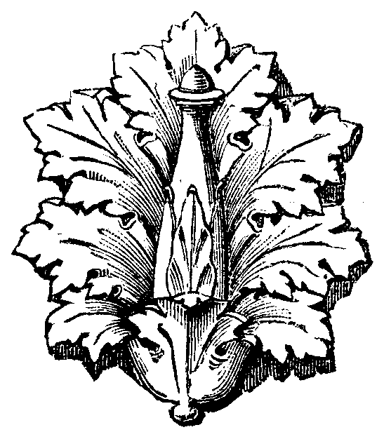
Fig. 5.
The deciphering and derivation of such forms as these is naturally enough more difficult; in the case of most of them we are not even in possession of the most necessary preliminaries to the investigation, and in the case of others there are very important links missing (e.g., for the well-known Greek palmettas). In proportion as the representation of the plant was a secondary object, the travesty has been more and more complete. As in the case of language, where the root is hardly recognizable in the later word, so in decorative art the original form is indistinguishable in the ornament. The migration of races and the early commercial intercourse between distant lands have done much to bring about the fusion of types; but again in contrast to this we find, in the case of extensive tracts of country, notably in the Asiatic continent, a fixity, throughout centuries, of forms that have once been introduced, which occasions a confusion between ancient and modern works of art, and renders investigations much more difficult. An old French traveler writes: "J'ai vu dans le trésor d'Ispahan les vetements de Tamerlan; ils ne different en rien de ceux d'aujourd'hui." Ethnology, the natural sciences, and last, but not least, the history of technical art are here set face to face with great problems.
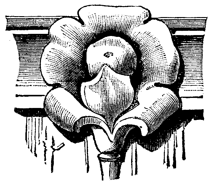
FIG. 6.
In the case in point, the study of the first group of artistic forms that have been elaborated by Western art leads to definite results, because the execution of the forms in stone can be followed on monuments that are relatively not very old, that are dated, and of which the remains are still extant. In order to follow the development, I ask your permission to go back at once to the very oldest of the known forms. They come down to us from the golden era of Greek decorative art—from the fourth or fifth century B.C.—when the older simple styles of architecture were supplanted by styles characterized by a greater richness of structure and more developed ornament. A number of flowers from capitals in Priene, Miletus, Eleusis, Athens (monument of Lysicrates), and Pergamon; also flowers from the calathos of a Greek caryatid in the Villa Albani near Rome, upon many Greek sepulchral wreaths, upon the magnificent gold helmet of a Grecian warrior (in the Museum of St. Petersburg)—these show us the simplest type of the pattern in question, a folded leaf, that has been bulged out, inclosing a knob or a little blossom (see Figs. 3 and 4). This is an example from the Temple of Apollo at Miletus, one that was constructed about ten years ago, for educational purposes. Here is the specimen of the flower of the monument to Lysicrates at Athens, of which the central part consists of a small flower or fruits (Figs. 5 and 6).

FIG. 7.
The form passes over into Roman art. The larger scale of the buildings, and the pretensions to a greater richness in details, lead to a further splitting up of the leaf into acanthus-like forms. Instead of a fruit-form a fir-cone appears, or a pine-apple or other fruit in an almost naturalistic form.
In a still larger scale we have the club-shaped knob developing into a plant-stem branching off something after the fashion of a candelabrum, and the lower part of the leaf, where it is folded together in a somewhat bell-shaped fashion, becomes in the true sense of the word a campanulum, out of which an absolute vessel-shaped form, as e.g. is to be seen in the frieze of the Basilica Ulpia in Rome, becomes developed.

FIG. 8.
Such remains of pictorial representation as are still extant present us with an equally perfect series of developments. The splendid Græco-Italian vessels, the richly ornamented Apulian vases, show flowers in the spirals of the ornaments, and even in the foreground of the pictorial representations, which correspond exactly to the above mentioned Greek relief representations. [The lecturer sent round, among other illustrations, a small photograph of a celebrated vase in Naples (representing the funeral rites of Patroclus), in which the flower in question appears in the foreground, and is perhaps also employed as ornament.] (Figs. 7 and 8.)
The Pompeian paintings and mosaics, and the Roman paintings, of which unfortunately very few specimens have come down to us, show that the further developments of this form were most manifold, and indeed they form in conjunction with the Roman achievements in plastic art the highest point that this form reached in its development, a point that the Renaissance, which followed hard upon it, did not get beyond.
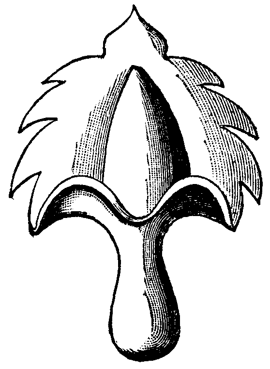
FIG. 9.
Thus the work of Raphael from the loggias follows in unbroken succession upon the forms from the Thermæ of Titus. It is only afterward that a freer handling of the traditional pattern arose, characterized by the substitution of, for instance, maple or whitethorn for the acanthus-like forms. Often even the central part falls away completely, or is replaced by overlapping leaves. In the forms of this century we have the same process repeated. Schinkel and Botticher began with the Greek form, and have put it to various uses; Stuler, Strack, Gropius, and others followed in their wake until the more close resemblance to the forms of the period of the Renaissance in regard to Roman art which characterizes the present day was attained (Fig. 9).
Now, what plant suggested this almost indispensable form of ornament, which ranks along with the acanthus and palmetta, and which has also become so important by a certain fusion with the structural laws of both?
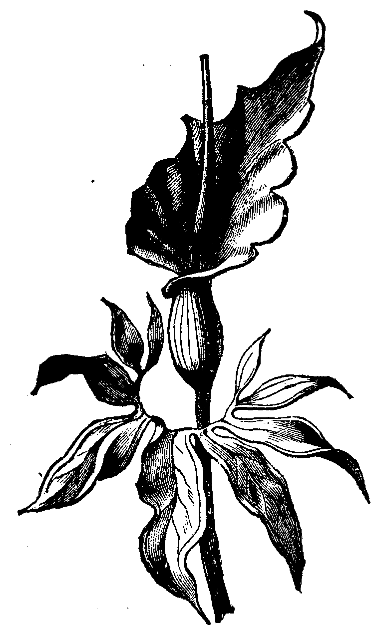
FIG. 10.
We meet with organism of the form in the family of the Araceæ, or aroid plants. An enveloping leaf (bract), called the spathe, which is often brilliantly colored, surrounds the florets, or fruits, that are disposed upon a spadix. Even the older writers—Theophrastus, Dioscorides, Galen, and Pliny—devote a considerable amount of attention to several species of this interesting family, especially to the value of their swollen stems as a food-stuff, to their uses in medicine, etc. Some species of Arum were eaten, and even nowadays the value of the swollen stems of some species of the family causes them to be cultivated, as, for instance, in Egypt and India, etc. (the so-called Portland sago, Portland Island arrowroot, is prepared from the swollen stems of Arum maculatum). In contrast with the smooth or softly undulating outlines of the spathe of Mediterranean Araceæ, one species stands out in relief, in which the sharply-marked fold of the spathe almost corresponds to the forms of the ornaments which we are discussing. It is Dracunculus vulgaris, and derives its name from its stem, which is spotted like a snake. This plant, which is pretty widely distributed in olive woods and in the river valleys of the countries bordering on the Mediterranean, was employed to a considerable extent in medicine by the ancients (and is so still nowadays, according to Von Heldreich, in Greece). It was, besides, the object of particular regard, because it was said not only to heal snake-bite, but the mere fact of having it about one was supposed to keep away snakes, who were said altogether to avoid the places where it grew. But, apart from this, the striking appearance of this plant, which often grows to an enormous size, would be sufficient to suggest its employment in art. According to measurements of Dr. Julius Schmidt, who is not long since dead, and was the director of the Observatory at Athens, a number of these plants grow in the Valley of Cephisus, and attain a height of as much as two meters, the spathe alone measuring nearly one meter. [The lecturer here exhibited a drawing (natural size) of this species, drawn to the measurements above referred to.]
FIG. 11.
Dr. Sintenis, the botanist, who last year traveled through Asia Minor and Greece, tells me that he saw beautiful specimens of the plant in many places, e.g., in Assos, in the neighborhood of the Dardanelles, under the cypresses of the Turkish cemeteries.
The inflorescence corresponds almost exactly to the ornament, but the multipartite leaf has also had a particular influence upon its development and upon that of several collateral forms which I cannot now discuss. The shape of the leaf accounts for several as yet unexplained extraordinary forms in the ancient plane-ornament, and in the Renaissance forms that have been thence developed. It first suggested the idea to me of studying the plant attentively after having had the opportunity five years ago of seeing the leaves in the Botanic Gardens at Pisa. It was only afterward that I succeeded in growing some flowers which fully confirmed the expectations that I had of them (Figs. 10 and 11).
FIG. 12.
The leaf in dracunculus has a very peculiar shape; it consists of a number of lobes which are disposed upon a stalk which is more or less forked (tends more or less to dichotomize). If you call to your minds some of the Pompeian wall decorations, you will perceive that similar forms occur there in all possible variations. Stems are regularly seen in decorations that run perpendicularly, surrounded by leaves of this description. Before this, these suggested the idea of a misunderstood (or very conventional) perspective representation of a circular flower. Now the form also occurs in this fashion, and thus negatives the idea of a perspective representation of a closed flower. It is out of this form in combination with the flower-form that the series of patterns was developed which we have become acquainted with in Roman art, especially in the ornament of Titus' Thermæ and in the Renaissance period in Raphael's work. [The lecturer here explained a series of illustrations of the ornaments referred to (Figs. 12, 13, 14).]
The attempt to determine the course of the first group of forms has been to a certain extent successful, but we meet greater difficulties in the study of the second.
FIG. 13.
It is difficult to obtain a firm basis on which to conduct our investigations from the historical or geographical point of view into this form of art, which was introduced into the West by Arabico-Moorish culture, and which has since been further developed here. There is only one method open to us in the determination of the form, which is to pass gradually from the richly developed and strongly differentiated forms to the smaller and simpler ones, even if these latter should have appeared contemporaneously or even later than the former. Here we have again to refer to the fact that has already been mentioned, to wit, that Oriental art remained stationary throughout long periods of time. In point of fact, the simpler forms are invariably characterized by a nearer and nearer approach to the more ancient patterns and also to the natural flower-forms of the Araceæ. We find the spathe, again, sometimes drawn like an acanthus leaf, more often, however, bulged out, coming to be more and more of a mere outline figure, and becoming converted into a sort of background; then the spadix, generally conical in shape, sometimes, however, altogether replaced by a perfect thistle, at other times again by a pomegranate. Auberville, in his magnificent work "L'Ornement des Tissus," is astonished to find the term pomegranate-pattern almost confined to these forms, since their central part is generally formed of a thistle-form. As far as I can discover in the literature that is at my disposal, this question has not had any particular attention devoted to it except in the large work upon Ottoman architecture published in Constantinople under the patronage of Edhem Pasha. The pomegranate that has served as the original of the pattern in question is in this work surrounded with leaves till it gives some sort of an approach to the pattern. (There are important suggestions in the book as to the employment of melon-forms.) Whoever has picked the fruit from the tender twigs of the pomegranate tree, which are close set with small altered leaves, will never dream of attributing the derivation of the thorny leaves that appear in the pattern to pomegranate leaves at any stage of their development.
FIG. 14
It does not require much penetration to see that the outline of the whole form corresponds to the spathe of the Araceæ, even although in later times the jagged contour is all that has remained of it, and it appears to have been provided with ornamental forms quite independently of the rest of the pattern. The inner thistle-form cannot be derived from the common thistle, because the surrounding leaves negative any such idea. The artichoke theory also has not enough in its favor, although the artichoke, as well as the thistle, was probably at a later time directly pressed into service. Prof. Ascherson first called my attention to the extremely anciently cultivated plant, the safflor (Carthamus tinctoris, Fig. 15), a thistle plant whose flowers were employed by the ancients as a dye. Some drawings and dried specimens, as well as the literature of the subject, first gave me a hope to find that this plant was the archetype of this ornament, a hope that was borne out by the study of the actual plant, although I was unable to grow it to any great perfection.
In the days of the Egyptian King Sargo (according to Ascherson and Schweinfurth) this plant was already well known as a plant of cultivation; in a wild state it is not known (De Candolle, "Originel des Plantes cultivées"). In Asia its cultivation stretches to Japan. Semper cites a passage from an Indian drama to the effect that over the doorway there was stretched an arch of ivory, and about it were bannerets on which wild safran (Saflor) was painted.
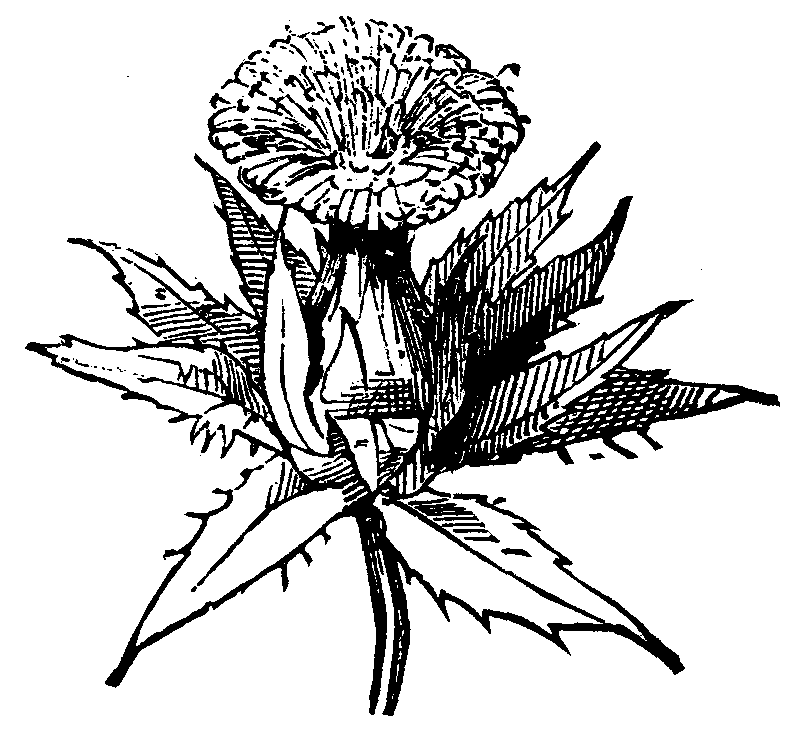
FIG. 15
The importance of the plant as a dye began steadily to decrease, and it has now ceased to have any value as such in the face of the introduction of newer coloring matters (a question that was treated of in a paper read a short time ago by Dr. Reimann before this Society). Perhaps its only use nowadays is in the preparation of rouge (rouge végétale).
But at a time when dyeing, spinning, and weaving were, if not in the one hand, yet at any rate intimately connected with one another in the narrow circle of a home industry, the appearance of this beautiful gold-yellow plant, heaped up in large masses, would be very likely to suggest its immortalization in textile art, because the drawing is very faithful to nature in regard to the thorny involucre. Drawings from nature of the plant in the old botanical works of the sixteenth and seventeenth centuries look very like ornamental patterns. Now after the general form had been introduced, pomegranates or other fruits—for instance, pine-apples—were introduced within the nest of leaves.
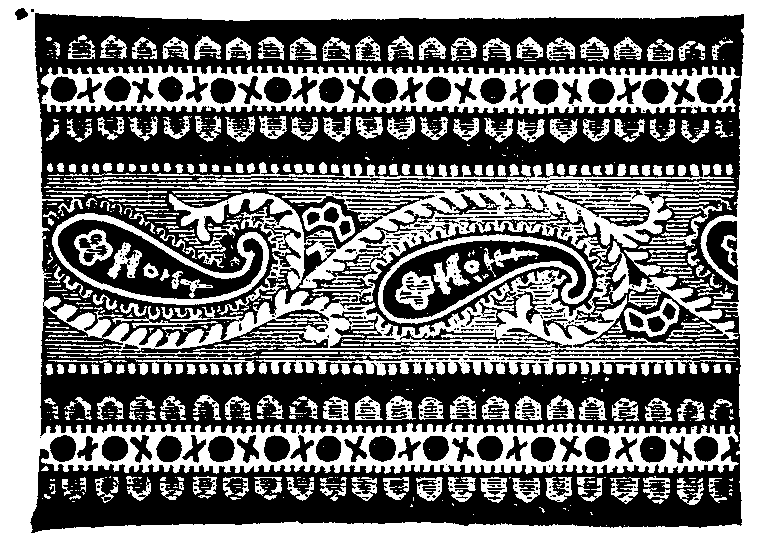
FIG. 16.
Into the detailed study of the intricacies of this subject I cannot here enter; the East-Asian influences are not to be neglected, which had probably even in early times an effect upon the form that was assumed, and have fused the correct style of compound flowers for flat ornament with the above-mentioned forms, so as to produce peculiar patterns; we meet them often in the so-called Persian textures and flat ornaments (Fig. 16).
We now come to the third group of forms—the so-called Cashmere pattern, or Indian palmetta. The developed forms, which, when they have attained their highest development, often show us outlines that are merely fanciful, and represent quite a bouquet of flowers leaning over to one side, and springing from a vessel (the whole corresponding to the Roman form with the vessel), must be thrown to one side, while we follow up the simpler forms, because in this case also we have no information as to either the where or the when the forms originated. (Figs. 17, 18, 19.)

FIG. 17.
Here again we are struck by resemblances to the forms that were the subjects of our previous study, we even come across direct transitional forms, which differ from the others only by the lateral curve of the apex of the leaf; sometimes it is the central part, the spadix, that is bent outward, and the very details show a striking agreement with the structure of the aroid inflorescence, so much so that one might regard them as actually copied from them.
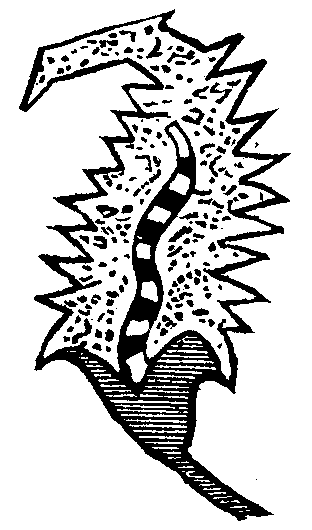
FIG. 18.
This form of ornament has been introduced into Europe since the French expedition to Egypt, owing to the importation of genuine Cashmere shawls. (When it cropped up in isolated forms, as in Venice in the fifteenth century, it appears not to have exerted any influence; its introduction is perhaps rather to be attributed to calico-printing.) Soon afterward the European shawl-manufacture, which is still in a flourishing state, was introduced. Falcot informs us that designs of a celebrated French artist, Couder, for shawl-patterns, a subject that he studied in India itself, were exported back to that country and used there (Fig. 20).
In these shawl-patterns the original simple form meets us in a highly developed, magnificent, and splendidly colored differentiation and elaboration. This we can have no scruples in ranking along with the mediæval plane-patterns, which we have referred to above, among the highest achievements of decorative art.
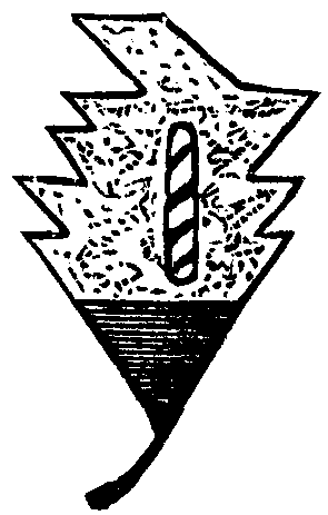
FIG. 19.
It is evident that it, at any rate in this high stage of development, resisted fusion with Western forms of art. It is all the more incumbent upon us to investigate the laws of its existence, in order to make it less alien to us, or perhaps to assimilate it to ourselves by attaining to an understanding of those laws. A great step has been made when criticism has, by a more painstaking study, put itself into a position to characterize as worthless ignorantly imitated, or even original, miscreations such as are eternally cropping up. If we look at our modern manufactures immediately after studying patterns which enchant us with their classical repose, or after it such others as captivate the eye by their beautiful coloring, or the elaborative working out of their details, we recognize that the beautifully balanced form is often cut up, choked over with others, or mangled (the flower springing up side down from the leaves), the whole being traversed at random by spirals, which are utterly foreign to the spirit of such a style, and all this at the caprice of uncultured, boorish designers. Once we see that the original of the form was a plant, we shall ever in the developed, artistic form cling, in a general way at least, to the laws of its organization, and we shall at any rate be in a position to avoid violent incongruities.
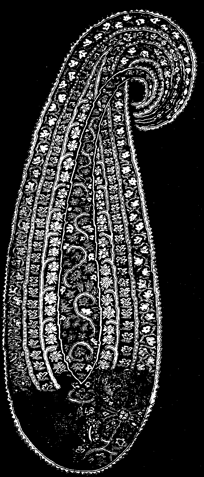
FIG. 20.
I had resort, a few years ago, to the young botanist Ruhmer, assistant at the Botanical Museum at Schöneberg, who has unfortunately since died of some chest-disease, in order to get some sort of a groundwork for direct investigations. I asked him to look up the literature of the subject, with respect to the employment of the Indian Araceæ for domestic uses or in medicine. A detailed work on the subject was produced, and establishes that, quite irrespective of species of Alocasia and Colocasia that have been referred to, a large number of Araceæ were employed for all sorts of domestic purposes. Scindapsus, which was used as a medicine, has actually retained a Sanskrit name, "vustiva." I cannot here go further into the details of this investigation, but must remark that even the incomplete and imperfect drawings of these plants, which, owing to the difficulty of preserving them, are so difficult to collect through travelers, exhibit such a wealth of shape, that it is quite natural that Indian and Persian flower-loving artists should be quite taken with them, and employ them enthusiastically in decorative art. Let me also mention that Haeckel, in his '"Letters of an Indian Traveler," very often bears witness to the effect of the Araceæ upon the general appearance of the vegetation, both in the full and enormous development of species of Caladia and in the species of Pothos which form such impenetrable mazes of interlooping stems.
In conclusion, allow me to remark that the results of my investigation, of which but a succinct account has been given here, negative certain derivations, which have been believed in, though they have never been proved; such as that of the form I have last discussed from the Assyrian palmetta, or from a cypress bent down by the wind. To say the least the laws of formation here laid down have a more intimate connection with the forms as they have come down to us, and give us a better handle for future use and development. The object of the investigation was, in general words, to prepare for an explanation of the questions raised; and even if the results had turned out other than they have, it would have sufficed me to have given an impulse to labors which will testify to the truth of the dead master's words:
    "Was Du ererbt von deinen Vätern hast,
    Erwirb es, um es zu besitzen."
[1]
The now well known kinetic theory of gases is a step so important in the way of explaining seemingly static properties of matter by motion, that it is scarcely possible to help anticipating in idea the arrival at a complete theory of matter, in which all its properties will be seen to be merely attributes of motion. If we are to look for the origin of this idea we must go back to Democritus, Epicurus, and Lucretius. We may then, I believe, without missing a single step, skip 1800 years. Early last century we find in Malebranche's "Recherche de la Verite," the statement that "la durete de corps" depends on "petits tourbillons."2 These words, embedded in a hopeless mass of unintelligible statements of the physical, metaphysical, and theological philosophies of the day, and unsupported by any explanation, elucidation, or illustration throughout the rest of the three volumes, and only marred by any other single sentence or word to be found in the great book, still do express a distinct conception which forms a most remarkable step toward the kinetic theory of matter. A little later we have Daniel Bernoulli's promulgation of what we now accept as a surest article of scientific faith—the kinetic theory of gases. He, so far as I know, thought only of Boyle's and Mariotte's law of the "spring of air," as Boyle called it, without reference to change of temperature or the augmentation of its pressure if not allowed to expand for elevation of temperature, a phenomenon which perhaps he scarcely knew, still less the elevation of temperature produced by compression, and the lowering of temperature by dilatation, and the consequent necessity of waiting for a fraction of a second or a few seconds of time (with apparatus of ordinary experimental magnitude), to see a subsidence from a larger change of pressure down to the amount of change that verifies Boyle's law. The consideration of these phenomena forty years ago by Joule, in connection with Bernoulli's original conception, formed the foundation of the kinetic theory of gases as we now have it. But what a splendid and useful building has been placed on this foundation by Clausius and Maxwell, and what a beautiful ornament we see on the top of it in the radiometer of Crookes, securely attached to it by the happy discovery of Tait and Dewar,3 that the length of the free path of the residual molecules of air in a good modern vacuum may amount to several inches! Clausius' and Maxwell's explanations of the diffusion of gases, and of thermal conduction in gases, their charmingly intelligible conclusion that in gases the diffusion of heat is just a little more rapid than the diffusion of molecules, because of the interchange of energy in collisions between molecules,4 while the chief transference of heat is by actual transport of the molecules themselves, and Maxwell's explanation of the viscosity of gases, with the absolute numerical relations which the work of those two great discoverers found among the three properties of diffusion, thermal conduction, and viscosity, have annexed to the domain of science a vast and ever growing province.
Rich as it is in practical results, the kinetic theory of gases, as hitherto developed, stops absolutely short at the atom or molecule, and gives not even a suggestion toward explaining the properties in virtue of which the atoms or molecules mutually influence one another. For some guidance toward a deeper and more comprehensive theory of matter, we may look back with advantage to the end of last century and beginning of this century, and find Rumford's conclusion regarding the heat generated in boring a brass gun: "It appears to me to be extremely difficult, if not quite impossible, to form any distinct idea of anything capable of being excited and communicated in the manner the heat was excited and communicated in these experiments, except it be MOTION;" and Davy's still more suggestive statements: "The phenomena of repulsion are not dependent on a peculiar elastic fluid for their existence." ... "Heat may be defined as a peculiar motion, probably a vibration, of the corpuscles of bodies, tending to separate them." ... "To distinguish this motion from others, and to signify the causes of our sensations of heat, etc., the name repulsive motion has been adopted." Here we have a most important idea. It would be somewhat a bold figure of speech to say the earth and moon are kept apart by a repulsive motion; and yet, after all, what is centrifugal force but a repulsive motion, and may it not be that there is no such thing as repulsion, and that it is solely by inertia that what seems to be repulsion is produced? Two bodies fly together, and, accelerated by mutual attraction, if they do not precisely hit one another, they cannot but separate in virtue of the inertia of their masses. So, after dashing past one another in sharply concave curves round their common center of gravity, they fly asunder again. A careless onlooker might imagine they had repelled one another, and might not notice the difference between what he actually sees and what he would see if the two bodies had been projected with great velocity toward one another, and either colliding and rebounding, or repelling one another into sharply convex continuous curves, fly asunder again.
Joule, Clausius, and Maxwell, and no doubt Daniel Bernoulli himself, and I believe every one who has hitherto written or done anything very explicit in the kinetic theory of gases, has taken the mutual action of molecules in collision as repulsive. May it not after all be attractive? This idea has never left my mind since I first read Davy's "Repulsive Motion," about thirty-five years ago, and I never made anything of it, at all events have not done so until to-day (June 16, 1884)—if this can be said to be making anything of it—when, in endeavoring to prepare the present address, I notice that Joule's and my own old experiments5 on the thermal effect of gases expanding from a high-pressure vessel through a porous plug, proves the less dense gas to have greater intrinsic potential energy than the denser gas, if we assume the ordinary hypothesis regarding the temperature of a gas, according to which two gases are of equal temperatures6 when the kinetic energies of their constituent molecules are of equal average amounts per molecule.
Think of the thing thus. Imagine a great multitude of particles inclosed by a boundary which may be pushed inward in any part all round at pleasure. Now station an engineer corps of Maxwell's army of sorting demons all round the inclosure, with orders to push in the boundary diligently everywhere, when none of the besieged troops are near, and to do nothing when any of them are seen approaching, and until after they have turned again inward. The result will be that, with exactly the same sum of kinetic and potential energies of the same inclosed multitude of particles, the throng has been caused to be denser. Now Joule's and my own old experiments on the efflux of air prove that if the crowd be common air, or oxygen, or nitrogen, or carbonic acid, the temperature is a little higher in the denser than in the rarer condition when the energies are the same. By the hypothesis, equality of temperature between two different gases or two portions of the same gas at different densities means equality of kinetic energies in the same number of molecules of the two. From our observations proving the temperature to be higher, it therefore follows that the potential energy is smaller in the condensed crowd. This—always, however, under protest as to the temperature hypothesis—proves some degree of attraction among the molecules, but it does not prove ultimate attraction between two molecules in collision, or at distances much less than the average mutual distance of nearest neighbors in the multitude. The collisional force might be repulsive, as generally supposed hitherto, and yet attraction might predominate in the whole reckoning of difference between the intrinsic potential energies of the more dense and less dense multitudes.
It is however remarkable that the explanation of the propagation of sound through gases, and even of the positive fluid pressure of a gas against the sides of the containing vessel, according to the kinetic theory of gases, is quite independent of the question whether the ultimate collisional force is attractive or repulsive. Of course it must be understood that, if it is attractive, the particles must, be so small that they hardly ever meet—they would have to be infinitely small to never meet—that, in fact, they meet so seldom, in comparison with the number of times their courses—are turned through large angles by attraction, that the influence of these surely attractive collisions is preponderant over that of the comparatively very rare impacts from actual contact. Thus, after all, the train of speculation suggested by Davy's "Repulsive Motion" does not allow us to escape from the idea of true repulsion, does not do more than let us say it is of no consequence, nor even say this with truth, because, if there are impacts at all, the nature of the force during the impact and the effects of the mutual impacts, however rare, cannot be evaded in any attempt to realize a conception of the kinetic theory of gases. And in fact, unless we are satisfied to imagine the atoms of a gas as mathematical points endowed with inertia, and as, according to Boscovich, endowed with forces of mutual, positive, and negative attraction, varying according to some definite function of the distance, we cannot avoid the question of impacts, and of vibrations and rotations of the molecules resulting from impacts, and we must look distinctly on each molecule as being either a little elastic solid or a configuration of motion in a continuous all-pervading liquid. I do not myself see how we can ever permanently rest anywhere short of this last view; but it would be a very pleasant temporary resting-place on the way to it if we could, as it were, make a mechanical model of a gas out of little pieces of round, perfectly elastic solid matter, flying about through the space occupied by the gas, and colliding with one another and against the sides of the containing vessel.
This is, in fact, all we have of the kinetic theory of gases up to the present time, and this has done for us, in the hands of Clausius and Maxwell, the great things which constitute our first step toward a molecular theory of matter. Of course from it we should have to go on to find an explanation of the elasticity and all the other properties of the molecules themselves, a subject vastly more complex and difficult than the gaseous properties, for the explanation of which we assume the elastic molecule; but without any explanation of the properties of the molecule itself, with merely the assumption that the molecule has the requisite properties, we might rest happy for a while in the contemplation of the kinetic theory of gases, and its explanation of the gaseous properties, which is not only stupendously important as a step toward a more thoroughgoing theory of matter, but is undoubtedly the expression of a perfectly intelligible and definite set of facts in Nature.
But alas for our mechanical model consisting of the cloud of little elastic solids flying about among one another. Though each particle have absolutely perfect elasticity, the end must be pretty much the same as if it were but imperfectly elastic. The average effect of repeated and repeated mutual collisions must be to gradually convert all the translational energy into energy of shriller and shriller vibrations of the molecule. It seems certain that each collision must have something more of energy in vibrations of very finely divided nodal parts than there was of energy in such vibrations before the impact. The more minute this nodal subdivision, the less must be the tendency to give up part of the vibrational energy into the shape of translational energy in the course of a collision; and I think it is rigorously demonstrable that the whole translational energy must ultimately become transformed into vibrational energy of higher and higher nodal subdivisions if each molecule is a continuous elastic solid. Let us, then, leave the kinetic theory of gases for a time with this difficulty unsolved, in the hope that we or others after us may return to it, armed with more knowledge of the properties of matter, and with sharper mathematical weapons to cut through the barrier which at present hides from us any view of the molecule itself, and of the effects other than mere change of translational motion which it experiences in collision.
To explain the elasticity of a gas was the primary object of the kinetic theory of gases. This object is only attainable by the assumption of an elasticity more complex in character, and more difficult of explanation, than the elasticity of gases—the elasticity of a solid. Thus, even if the fatal fault in the theory, to which I have alluded, did not exist, and if we could be perfectly satisfied with the kinetic theory of gases founded on the collisions of elastic solid molecules, there would still be beyond it a grander theory which need not be considered a chimerical object of scientific ambition—to explain the elasticity of solids. But we may be stopped when we commence to look in the direction of such a theory with the cynical question, What do you mean by explaining a property of matter? As to being stopped by any such question, all I can say is that if engineering were to be all and to end all physical science, we should perforce be content with merely finding properties of matter by observation, and using them for practical purposes. But I am sure very few, if any, engineers are practically satisfied with so narrow a view of their noble profession. They must and do patiently observe, and discover by observation, properties of matter and results of material combinations. But deeper questions are always present, and always fraught with interest to the true engineer, and he will be the last to give weight to any other objection to any attempt to see below the surface of things than the practical question, Is it likely to prove wholly futile? But now, instead of imagining the question, What do you mean by explaining a property of matter? to be put cynically, and letting ourselves be irritated by it, suppose we give to the questioner credit for being sympathetic, and condescend to try and answer his question. We find it not very easy to do so. All the properties of matter are so connected that we can scarcely imagine one thoroughly explained without our seeing its relation to all the others, without in fact having the explanation of all; and till we have this we cannot tell what we mean by "explaining a property" or "explaining the properties" of matter. But though this consummation may never be reached by man, the progress of science may be, I believe will be, step by step toward it, on many different roads converging toward it from all sides. The kinetic theory of gases is, as I have said, a true step on one of the roads. On the very distinct road of chemical science, St. Claire Deville arrived at his grand theory of dissociation without the slightest aid from the kinetic theory of gases. The fact that he worked it out solely from chemical observation and experiment, and expounded it to the world without any hypothesis whatever, and seemingly even without consciousness of the beautiful explanation it has in the kinetic theory of gases, secured for it immediately an independent solidity and importance as a chemical theory when he first promulgated it, to which it might even by this time scarcely have attained if it had first been suggested as a probability indicated by the kinetic theory of gases, and been only afterward confirmed by observation. Now, however, guided by the views which Clausius and Williamson have given us of the continuous interchange of partners between the compound molecules constituting chemical compounds in the gaseous state, we see in Deville's theory of dissociation a point of contact of the most transcendent interest between the chemical and physical lines of scientific progress.
To return to elasticity: if we could make out of matter devoid of elasticity a combined system of relatively moving parts which, in virtue of motion, has the essential characteristics of an elastic body, this would surely be, if not positively a step in the kinetic theory of matter, at least a fingerpost pointing a way which we may hope will lead to a kinetic theory of matter. Now this, as I have already shown,7 we can do in several ways. In the case of the last of the communications referred to, of which only the title has hitherto been published, I showed that, from the mathematical investigation of a gyrostatically dominated combination contained in the passage of Thomson and Tait's "Natural Philosophy" referred to, it follows that any ideal system of material particles, acting on one another mutually through massless connecting springs, may be perfectly imitated in a model consisting of rigid links jointed together, and having rapidly rotating fly wheels pivoted on some or on all of the links. The imitation is not confined to cases of equilibrium. It holds also for vibration produced by disturbing the system infinitesimally from a position of stable equilibrium and leaving it to itself. Thus we may make a gyrostatic system such that it is in equilibrium under the influence of certain positive forces applied to different points of this system; all the forces being precisely the same as, and the points of application similarly situated to, those of the stable system with springs. Then, provided proper masses (that is to say, proper amounts and distributions of inertia) be attributed to the links, we may remove the external forces from each system, and the consequent vibration of the points of application of the forces will be identical. Or we may act upon the systems of material points and springs with any given forces for any given time, and leave it to itself, and do the same thing for the gyrostatic system; the consequent motion will be the same in the two cases. If in the one case the springs are made more and more stiff, and in the other case the angular velocities of the fly wheels are made greater and greater, the periods of the vibrational constituents of the motion will become shorter and shorter, and the amplitudes smaller and smaller, and the motions will approach more and more nearly those of two perfectly rigid groups of material points moving through space and rotating according to the well known mode of rotation of a rigid body having unequal moments of inertia about its three principal axes. In one case the ideal nearly rigid connection between the particles is produced by massless, exceedingly stiff springs; in the other case it is produced by the exceedingly rapid rotation of the fly wheels in a system which, when the fly wheels are deprived of their rotation, is perfectly limp.
The drawings (Figs. 1 and 2) before you illustrate two such material systems.8 The directions of rotation of the fly-wheels in the gyrostatic system (Fig. 2) are indicated by directional ellipses, which show in perspective the direction of rotation of the fly-wheel of each gyrostat. The gyrostatic system (Fig. 2) might have been constituted of two gyrostatic members, but four are shown for symmetry. The inclosing circle represents in each case in section an inclosing spherical shell to prevent the interior from being seen. In the inside of one there are fly-wheels, in the inside of the other a massless spring. The projecting hooked rods seem as if they are connected by a spring in each case. If we hang any one of the systems up by the hook on one of its projecting rods, and hang a weight to the hook of the other projecting rod, the weight, when first put on, will oscillate up and down, and will go on doing so for ever if the system be absolutely unfrictional. If we check the vibration by hand, the weight will hang down at rest, the pin drawn out to a certain degree; and the distance drawn out will be simply proportional to the weight hung on, as in an ordinary spring balance.

FIG. 1

FIG. 2
Here, then, out of matter possessing rigidity, but absolutely devoid of elasticity, we have made a perfect model of a spring in the form of a spring balance. Connect millions of millions of particles by pairs of rods such as these of this spring balance, and we have a group of particles constituting an elastic solid; exactly fulfilling the mathematical ideal worked out by Navier, Poisson, and Cauchy, and many other mathematicians, who, following their example, have endeavored to found a theory of the elasticity of solids on mutual attraction and repulsion between a group of material particles. All that can possibly be done by this theory, with its assumption of forces acting according to any assumed law of relation to distance, is done by the gyrostatic system. But the gyrostatic system does, besides, what the system of naturally acting material particles cannot do—it constitutes an elastic solid which can have the Faraday magneto-optic rotation of the plane of polarization of light; supposing the application of our solid to be a model of the luminiferous ether for illustrating the undulatory theory of light. The gyrostatic model spring balance is arranged to have zero moment of momentum as a whole, and therefore to contribute nothing to the Faraday rotation; with this arrangement the model illustrates the luminiferous ether in a field unaffected by magnetic force. But now let there be a different rotational velocity imparted to the jointed square round the axis of the two projecting hooked rods, such as to give a resultant moment of momentum round any given line through the center of inertia of the system; and let pairs of the hooked rods in the model thus altered, which is no longer a model of a mere spring balance, be applied as connections between millions of pairs of particles as before, with the lines of resultant moment of momentum all similarly directed. We now have a model elastic solid which will have the property that the direction of vibration in waves of rectilinear vibrations propagated through it shall turn round the line of propagation of the waves, just as Faraday's observation proves to be done by the line of vibration of light in a dense medium between the poles of a powerful magnet. The case of wave front perpendicular to the lines of resultant moment of momentum (that is to say, the direction of propagation being parallel to these lines) corresponds, in our mechanical model, to the case of light traveling in the direction of the lines of force in a magnetic field.
In these illustrations and models we have different portions of ideal rigid matter acting upon one another, by normal pressure at mathematical points of contact—of course no forces of friction are supposed. It is exceedingly interesting to see how thus, with no other postulates than inertia, rigidity, and mutual impenetrability, we can thoroughly model not only an elastic solid, and any combination of elastic solids, but so complex and recondite a phenomenon as the passage of polarized light through a magnetic field. But now, with the view of ultimately discarding the postulate of rigidity from all our materials, let us suppose some to be absolutely destitute of rigidity, and to possess merely inertia and incompressibility, and mutual impenetrability with reference to the still remaining rigid matter. With these postulates we can produce a perfect model of mutual action at a distance between solid particles, fulfilling the condition, so keenly desired by Newton and Faraday, of being explained by continuous action through an intervening medium. The law of the mutual force in our model, however, is not the simple Newtonian law, but the much more complex law of the mutual action between electro magnets—with this difference, that in the hydro-kinetic model in every case the force is opposite in direction to the corresponding force in the electro-magnetic analogue. Imagine a solid bored through with a hole, and placed in our ideal perfect liquid. For a moment let the hole be stopped by a diaphragm, and let an impulsure pressure be applied for an instant uniformly over the whole membrane, and then instantly let the membrane be dissolved into liquid. This action originates a motion of the liquid relatively to the solid, of a kind to which I have given the name of "irrotational circulation," which remains absolutely constant however the solid be moved through the liquid. Thus, at any time the actual motion of the liquid at any point in the neighborhood of the solid will be the resultant of the motion it would have in virtue of the circulation alone, were the solid at rest, and the motion it would have in virtue of the motion of the solid itself, had there been no circulation established through the aperture. It is interesting and important to remark in passing that the whole kinetic energy of the liquid is the sum of the kinetic energies which it would have in the two cases separately. Now, imagine the whole liquid to be inclosed in an infinitely large, rigid, containing vessel, and in the liquid, at an infinite distance from any part of the containing vessel, let two perforated solids, with irrotational circulation through each, be placed at rest near one another. The resultant fluid motion due to the two circulations, will give rise to fluid pressure on the two bodies, which, if unbalanced, will cause them to move. The force systems—force-and-torques, or pairs of forces—required to prevent them from moving will be mutual and opposite, and will be the same as, but opposite in direction to, the mutual force systems required to hold at rest two electromagnets fulfilling the following specification: The two electro magnets are to be of the same shape and size as the two bodies, and to be placed in the same relative positions, and to consist of infinitely thin layers of electric currents in the surfaces of solids possessing extreme diamagnetic quality—in other words, infinitely small permeability. The distribution of electric current on each body may be any whatever which fulfills the condition that the total current across any closed line drawn on the surface once through the aperture is equal to ¼ π of the circulation9 through the aperture in the hydro-kinetic analogue.
It might be imagined that the action at a distance thus provided for by fluid motion could serve as a foundation for a theory of the equilibrium, and the vibrations, of elastic solids, and the transmission of waves like those of light through an extended quasi-elastic solid medium. But unfortunately for this idea the equilibrium is essentially unstable, both in the case of magnets and, notwithstanding the fact that the forces are oppositely directed, in the hydro-kinetic analogue also, when the several movable bodies (two or any greater number) are so placed relatively as to be in equilibrium. If, however, we connect the perforated bodies with circulation through them in the hydro-kinetic system, by jointed rigid connecting links, we may arrange for configurations of stable equilibrium. Thus, without fly-wheels, but with fluid circulations through apertures, we may make a model spring balance or a model luminiferous ether, either without or with the rotational quality corresponding to that of the true luminiferous ether in the magnetic fluid—in short, do all by the perforated solids with circulations through them that we saw we could do by means of linked gyrostats. But something that we cannot do by linked gyrostats we can do by the perforated bodies with fluid circulation: we can make a model gas. The mutual action at a distance, repulsive or attractive according to the mutual aspect of the two bodies when passing within collisional distance10 of one another, suffices to produce the change of direction of motion in collision, which essentially constitutes the foundation of the kinetic theory of gases, and which, as we have seen before, may as well be due to attraction as to repulsion, so far as we know from any investigation hitherto made in this theory.
There remains, however, as we have seen before, the difficulty of providing for the case of actual impacts between the solids, which must be done by giving them massless spring buffers or, which amounts to the same thing, attributing to them repulsive forces sufficiently powerful at very short distances to absolutely prevent impacts between solid and solid; unless we adopt the equally repugnant idea of infinitely small perforated solids, with infinitely great fluid circulations through them. Were it not for this fundamental difficulty, the hydro-kinetic model gas would be exceedingly interesting; and, though we could scarcely adopt it as conceivably a true representation of what gases really are, it might still have some importance as a model configuration of solid and liquid matter, by which without elasticity the elasticity of true gas might be represented.
But lastly, since the hydro-kinetic model gas with perforated solids and fluid circulations through them fails because of the impacts between the solids, let us annul the solids and leave the liquid performing irrotational circulation round vacancy,11 in the place of the solid cores which we have hitherto supposed; or let us annul the rigidity of the solid cores of the rings, and give them molecular rotation according to Helmholtz's theory of vortex motion. For stability the molecular rotation must be such as to give the same velocity at the boundary of the rotational fluid core as that of the irrotationally circulating liquid in contact with it, because, as I have proved, frictional slip between two portions of liquid in contact is inconsistent with stability. There is a further condition, upon which I cannot enter into detail just now, but which may be understood in a general way when I say that it is a condition of either uniform or of increasing molecular rotation from the surface inward, analogous to the condition that the density of a liquid, resting for example under the influence of gravity, must either be uniform or must be greater below than above for stability of equilibrium. All that I have said in favor of the model vortex gas composed of perforated solids with fluid circulations through them holds without modification for the purely hydro-kinetic model, composed of either Helmholtz cored vortex rings or of coreless vortices, and we are now troubled with no such difficulty as that of the impacts between solids. Whether, however, when the vortex theory of gases is thoroughly worked out, it will or will not be found to fail in a manner analogous to the failure which I have already pointed out in connection with the kinetic theory of gases composed of little elastic solid molecules, I cannot at present undertake to speak with certainty. It seems to me most probable that the vortex theory cannot fail in any such way, because all I have been able to find out hitherto regarding the vibration of vortices,12 whether cored or coreless, does not seem to imply the liability of translational or impulsive energies of the individual vortices becoming lost in energy of smaller and smaller vibrations.
As a step toward kinetic theory of matter, it is certainly most interesting to remark that in the quasi-elasticity, elasticity looking like that of an India-rubber band, which we see in a vibrating smoke-ring launched from an elliptic aperture, or in two smoke-rings which were circular, but which have become deformed from circularity by mutual collision, we have in reality a virtual elasticity in matter devoid of elasticity, and even devoid of rigidity, the virtual elasticity being due to motion, and generated by the generation of motion.
[1]Last year, when I had the pleasure of reading a paper before you on my new system of electric tramways, I ventured to express the hope that before twelve months had passed, "to be able to report progress," and I am happy to say that notwithstanding the wearisome delay and time lost in fruitless negotiations, and the hundred and one difficulties within and without that have beset me, I am able to appear before you again and tell you of advance.
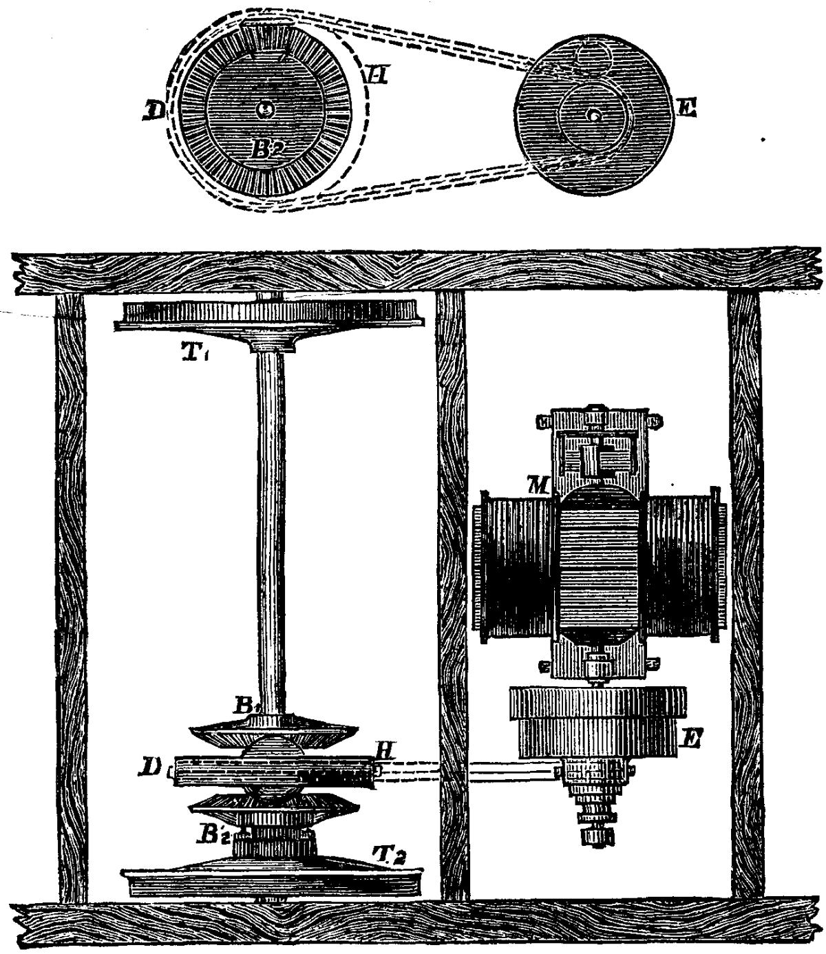
FIG. 1
Practical men know well that there is a wide difference between a model and a full sized machine; and when I decided to construct a full sized tramcar and lay out a full sized track, I found it necessary to make many alterations of detail, my chief difficulty being so to design my work as to facilitate construction and allow of compensation for that inaccuracy of workmanship which I have come to regard as inevitable.
In order to satisfy the directors of a tramway company of the practical nature of my system before disturbing their lines, I have laid, in a field near the works of Messrs. Smith, Baker & Co., Manchester, a track 110 yards long, 4 ft. 8½ in. gauge, and I have constructed a full sized street tramcar to run thereon. My negotiations being with a company in a town where there are no steep gradients, and where the coefficient of friction of ordinary wheels would be sufficient for all tractive purposes, I thought it better to avoid the complication involved in employing a large central wheel with a broad surface specially designed for hilly districts, and with which I had mounted a gradient of one in sixteen.
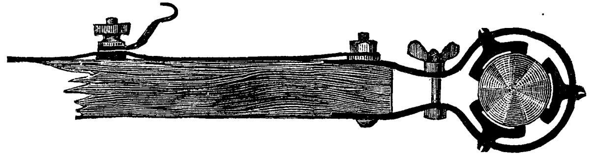
FIG. 2
But as the line in question was laid with all the curves unnecessarily quick, even those in the "pass-bies," I thought it expedient to employ differential gear, as illustrated at D, Fig. 1, which is a sketch plan showing the mechanism employed. M is a Siemens electric motor running at 650 revolutions per minute; E is a combination of box gearing, frictional clutch, and chain pinion, and from this pinion a steel chain passes around the chain-wheel, H, which is free to revolve upon the axle, and carries within it the differential pinion, gearing with the bevel-wheel, B², keyed upon the sleeve of the loose tram-wheel, T², and with the bevel-wheel, B¹, keyed upon the axle, to which the other tram-wheel, T¹, is attached. To the other tram-wheels no gear is connected; one of them is fast to the axle, and the other runs loose, but to them the brake is applied in the usual manner.
The electric current from the collector passes, by means of a copper wire, and a switch upon the dashboard of the car, and resistance coils placed under the seats, to the motor, and from the motor by means of an adjustable clip (illustrated in diagram, Fig. 2) to the axles, and by them through the four wheels to the rails, which form the return circuit.
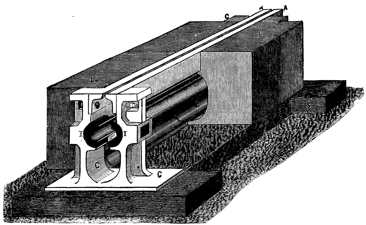
FIG. 3
I have designed many modifications of the track, but it is, perhaps, best at present to describe only that which I have in actual use, and it is illustrated in diagram, Fig. 3, which is a sectional and perspective view of the central channel. L is the surface of the road, and SS are the sleepers, CC are the chairs which hold the angle iron, AA forming the longitudinally slotted center rail and the electric lead, which consists of two half-tubes of copper insulated from the chairs by the blocks, I, I. A special brass clamp, free to slide upon the tube, is employed for this purpose, and the same form of clamp serves to join the two ends of the copper tubes together and to make electric contact. Two half-tubes instead of one slotted tube have been employed, in order to leave a free passage for dirt or wet to fall through the slot in the center rail to the drain space, G. Between chair and chair hewn granite or artificial stone is employed, formed, as shown in the drawing, to complete the surface of the road and to form a continuous channel or drain. In order that this drain may not become choked, at suitable intervals, in the length of the track, sump holes are formed as illustrated in diagram, Fig. 4 These sump holes have a well for the accumulation of mud, and are also connected with the main street drain, so that water can freely pass away. The hand holes afford facility for easily removing the dirt.
In a complete track these hand holes would occasionally be wider than shown here, for the purpose of removing or fixing the collector, Fig. 5, which consists of two sets of spirally fluted rollers free to revolve upon spindles, which are held by knuckle-joints drawn together by spiral springs; by this means the pressure of the rollers against the inside of the tube is constantly maintained, and should any obstruction occur in the tube the spiral flute causes it to revolve, thus automatically cleansing the tubes.
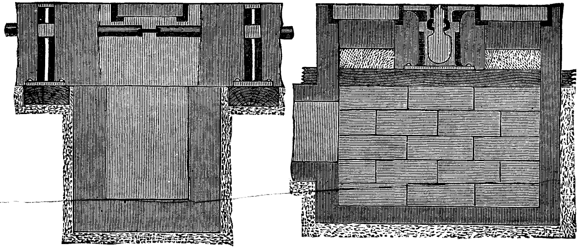
FIG. 4
The collector is provided with two steel plates, which pass through the slit in the center rail; the lower ends of these plates are clamped by the upper frame of the collector, insulating material being interposed, and the upper ends are held in two iron cheeks. Between these steel plates insulated copper strips are held, electrically connected with the collector and with the adjustable clip mounted upon the iron cheeks; this clip holds the terminal on the end of the wire (leading to the motor) firmly enough for use, the cheeks being also provided with studs for the attachment of leather straps hooked on to the framework of the car, one for the forward and one for backward movement of the collector. These straps are strong enough for the ordinary haulage of the collector, and for the removal of pebbles and dirt that may get into the slit; but should any absolute block occur then they break and the terminal is withdrawn from the clip; the electric contact being thereby broken the car stops, the obstruction can then be removed and the collector reconnected without damage and with little delay.
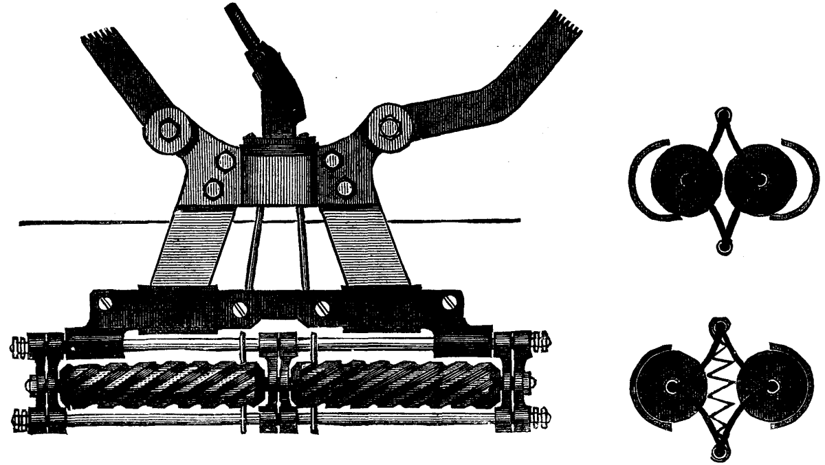
FIG. 5
In order to secure continuity of the center rail throughout the length of the track, and still provide for the removal of the collector at frequent intervals, the framework of the collector is so made that, by slackening the side-bolts, the steel plates can be drawn upward and the collector itself withdrawn sideways through the hand holes, one of the half-tubes being removed for the purpose.
Fig. 6 illustrates another arrangement that I have constructed, both of collector and method of collecting.
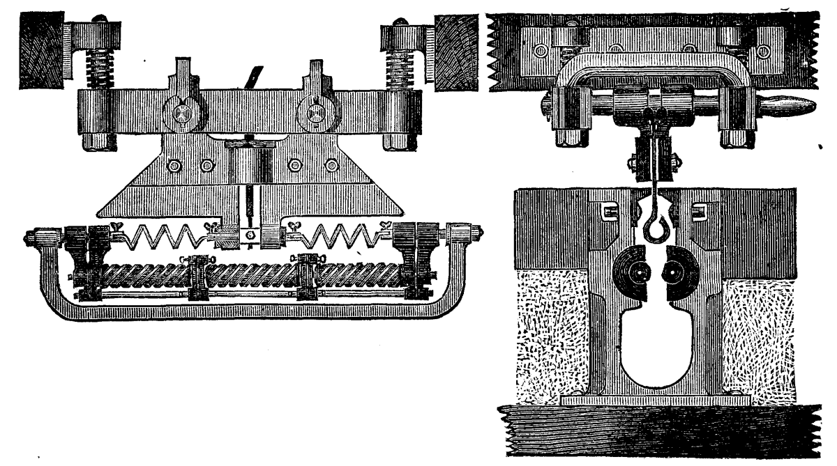
FIG. 6
As before mentioned, the arrangement now described has been carried out in a field near the works of Messrs. Smith, Baker & Co., Cornbrook Telegraph Works, Manchester, and its working efficiency has been most satisfactory. After a week of rain and during drenching showers the car ran with the same speed and under the same control as when the ground was dry.
This I account for by the theory that when the rails are wet and the tubes moist the better contact made compensates for the slight leakage that may occur.
At the commencement of my paper I promised to confine myself to work done; I therefore abstain from describing various modifications of detail for the same purpose. But one method of supporting and insulating the conductor in the channel may be suggested by an illustration of the plan I adopted for a little pleasure line in the Winter Gardens, Blackpool.
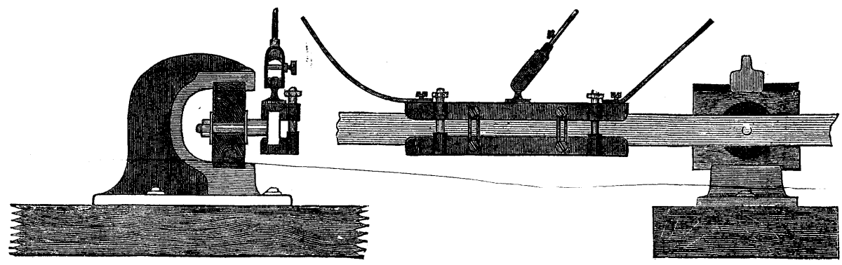
FIG. 7.
Fig. 7. There the track being exclusively for the electric railway, it was not necessary to provide a center channel; the conductor has therefore been placed in the center of the track, and consists of bar iron 1¼ in. by ½ in., and is held vertically by means of studs riveted into the side; these studs pass through porcelain insulators, and by means of wooden clamps and wedges are held in the iron chairs which rest upon the sleepers. The iron conductors were placed vertically to facilitate bending round the sharp curves which were unavoidable on this line.
The collector consists of two metal slippers held together by springs, attached to the car by straps and electrically connected to the motor by clips in the same manner as the one employed in Manchester.
I am glad to say that, notwithstanding the curves with a radius of 55 feet and gradients of 1 in 57, this line is also a practical success.
When the chief of the London Fire Brigade visited the United States in 1882, he was, as is the general rule on the other side of the Atlantic, "interviewed"—a custom, it may be remarked, which appears to be gaining ground also in this country. The inferences drawn from these interviews seem to be that the absence of large fires in London was chiefly due to the superiority of our fire brigade, and that the greater frequency of conflagrations in American cities, and particularly in New York, was due to the inferiority of their fire departments. How unjust such a comparison would be is shown in a paper presented by Mr. Edward B. Dorsey, a member of the American Society of Civil Engineers, to that association, in which the author discusses the comparative liability to and danger from conflagrations in London and in American cities. He found from an investigation which he conducted with much care during a visit to London that it is undoubtedly true that large fires are much less frequent in the metropolis than in American cities; but it is equally true that the circumstances existing in London and New York are quite different. As it is a well-known fact that the promptness, efficiency, and bravery of American firemen cannot be surpassed, we gladly give prominence to the result of the author's investigations into the true causes of the great liability of American cities to large fires. In a highly interesting comparison the writer has selected New York and London as typical cities, although his observations will apply to most American and English towns, if, perhaps, with not quite the same force. In the first place, the efforts of the London Fire Brigade receive much aid from our peculiarly damp climate. From the average of eleven years (1871-1881) of the meteorological observations made at the Greenwich Observatory, it appears that in London it rains, on the average, more than three days in the week, that the sun shines only one-fourth of the time he is above the horizon, and that the atmosphere only lacks 18 per cent. of complete saturation, and is cloudy seven-tenths of the time. Moreover, the humidity of the atmosphere in London is very uniform, varying but little in the different months. Under these circumstances, wood will not be ignited very easily by sparks or by contact with a weak flame. This is very different from the condition of wood in the long, hot, dry seasons of the American continent. The average temperature for the three winter months in London is 38.24 degrees Fahr.; in New York it is 31.56 degrees, or 6.68 degrees lower. This lower range of temperature must be the cause of many conflagrations, for, to make up for the deficiency in the natural temperature, there must be in New York many more and larger domestic fires. The following statistics, taken from the records of the New York Fire Department, show this. In the three winter months of 1881, January, February, and December, there were 522 fire alarms in New York, or an average per month of 174; in the remaining nine months 1,263, or an average per month of 140. In the corresponding three winter months of 1882 there were 602 fire alarms, or an average per month of 201; in the remaining nine months 1,401, or an average per month of 155. In round numbers there were in 1881 one-fourth, and in 1882 one-third more fire alarms in the three winter months than in the nine warmer months. We are not aware that similar statistics have ever been compiled for London, and are consequently unable to draw comparison; but, speaking from recollection, fires appear to be more frequent also in London during the winter months.
Another cause of the greater frequency of fires in New York and their more destructive nature is the greater density of population in that city. The London Metropolitan Police District covers 690 square miles, extending 12 to 15 miles in every direction from Charing Cross, and contained in 1881 a population of 4,764,312; but what is generally known as London covers 122 square miles, containing, in 1881, 528,794 houses, and a population of 3,814,574, averaging 7.21 persons per house, 49 per acre, and 31,267 per square mile. Now let us look at New York. South of Fortieth Street between the Hudson and East Rivers, New York has an area of 3,905 acres, a fraction over six square miles, exclusive of piers, and contained, according to the census of 1880, a population of 813,076. This gives 208 persons per acre. The census of 1880 reports the total number of dwellings in New York at 73,684; total population, 1,206,299; average per dwelling, 16.37. Selecting for comparison an area about equal from the fifteen most densely populated districts or parishes of London, of an aggregate area of 3,896 acres, and with a total population of 746,305, we obtain 191.5 persons per acre. Thus briefly New York averaged 208 persons per acre, and 16.37 per dwelling; London, for the same area, 191.5 persons per acre, and 7.21 per house. But this comparison is scarcely fair, as in London only the most populous and poorest districts are included, corresponding to the entirely tenement districts of New York, while in the latter city it includes the richest and most fashionable sections, as well as the poorest. If tenement districts were taken alone, the population would be found much more dense, and New York proportionately much more densely populated. Taking four of the most thickly populated of the London districts (East London, Strand, Old Street, St. Luke's, St. Giles-in-the-Fields, and St. George, Bloomsbury), we find on a total area of 792 acres a population of 197,285, or an average of 249 persons per acre. In four of the most densely populated wards of New York (10th, 11th, 13th, and 17th), we have on an area of 735 acres a population of 258,966, or 352 persons per acre. This is 40 per cent. higher than in London, the districts being about the same size, each containing about 1-1/5 square miles. Apart from the greater crowding which takes place in New York, and the different style of buildings, another very fertile cause of the spreading of fires is the freer use of wood in their construction. It is asserted that in New York there is more than double the quantity of wood used in buildings per acre than in London. From a house census undertaken in 1882 by the New York Fire Department, moreover, it appears that there were 106,885 buildings including sheds, of which 28,798 houses were built of wood or other inflammable materials, besides 3,803 wooden sheds, giving a total of 32,601 wooden buildings.
We are not aware that there are any wooden houses left in London. There are other minor causes which act as checks upon the spreading of fires in London. London houses are mostly small in size, and fires are thus confined to a limited space between brick walls. Their walls are generally low and well braced, which enable the firemen to approach them without danger. About 60 per cent. of London houses are less than 22 feet high from the pavement to the eaves; more than half of the remainder are less than 40 feet high, very few being over 50 feet high. This, of course, excludes the newer buildings in the City. St. James's Palace does not exceed 40 feet, the Bank of England not over 30 feet in height; but these are exceptional structures. Fireproof roofings and projecting party walls also retard the spreading of conflagrations. The houses being comparatively low and small, the firemen are enabled to throw water easily over them, and to reach their roofs with short ladders. There is in London an almost universal absence of wooden additions and outbuildings, and the New York ash barrel or box kept in the house is also unknown. The local authorities in London keep a strict watch over the manufacture or storage of combustible materials in populous parts of the city. Although overhead telegraph wires are multiplying to an alarming extent in London, their number is nothing to be compared to their bewildering multitude in New York, where their presence is not only a hinderance to the operations of the firemen, but a positive danger to their lives. Finally—and this has already been partly dealt with in speaking of the comparative density of population of the two cities—a look at the map of London will show us how the River Thames and the numerous parks, squares, private grounds, wide streets, as well as the railways running into London, all act as effectual barriers to the extension of fires.
The recent great conflagrations in the city vividly illustrate to Londoners what fire could do if their metropolis were built on the New York plan. The City, however, as we have remarked, is an exceptional part of London, and, taking the British metropolis as it is, with its hundreds of square miles of suburbs, and contrasting its condition with that of New York, we are led to adopt the opinion that London, with its excellent fire brigade, is safe from a destructive conflagration. It was stated above, and it is repeated here, that the fire brigade of New York is unsurpassed for promptness, skill, and heroic intrepidity, but their task, by contrast, is a heavy one in a city like New York, with its numerous wooden buildings, wooden or asphalt roofs, buildings from four to ten stories high, with long unbraced walls, weakened by many large windows, containing more than ten times the timber an average London house does, and that very inflammable, owing to the dry and hot American climate. But this is not all. In New York we find the five and six story tenement houses with two or three families on each floor, each with their private ash barrel or box kept handy in their rooms, all striving to keep warm during the severe winters of North America. We also find narrow streets and high buildings, with nothing to arrest the extension of a fire except a few small parks, not even projecting or effectual fire-walls between the several buildings. And to all this must be added the perfect freedom with which the city authorities of New York allow in its most populous portions large stables, timber yards, carpenters' shops, and the manufacture and storage of inflammable materials. Personal liberty could not be carried to a more dangerous extent. We ought to be thankful that in such matters individual freedom is somewhat hampered in our old-fashioned and quieter-going country.—London Morning Post.
The gape worm may be termed the bete noir of the poultry-keeper—his greatest enemy—whether he be farmer or fancier. It is true there are some who declare that it is unknown in their poultry-yards—that they have never been troubled with it at all. These are apt to lay it down, as I saw a correspondent did in a recent number of the Country Gentleman, that the cause is want of cleanliness or neglect in some way. But I can vouch that that is not so. I have been in yards where everything was first-rate, where the cleanliness was almost painfully complete, where no fault in the way of neglect could be found, and yet the gapes were there; and on the other hand, I have known places where every condition seemed favorable to the development of such a disease, and there it was absent—this not in isolated cases, but in many. No, we must look elsewhere for the cause.
Observations lead me to the belief that gapes are more than usually troublesome during a wet spring or summer following a mild winter. This would tend to show that the egg from which the worm (that is in itself the disease) emerges is communicated from the ground, from the food eaten, or the water drunk, in the first instance, but it is more than possible that the insects themselves may pass from one fowl to another. All this we can accept as a settled fact, and also any description of the way in which the parasitic worms attach themselves to the throats of the birds, and cause the peculiar gaping of the mouth which gives the name to the disease.
Many remedies have been suggested, and my object now is to communicate some of the later ones—thus to give a variety of methods, so that in case of the failure of one, another will be at hand ready to be tried. It is a mistake always to pin the faith to one remedy, for the varying conditions found in fowls compel a different treatment. The old plan of dislodging the worms with a feather is well known, and need not be described again. But I may mention that in this country some have found the use of an ointment, first suggested by Mr. Lewis Wright, I believe, most valuable. This is made of mercurial ointment, two parts; pure lard, two parts; flour of sulphur, one part; crude petroleum, one part—and when mixed together is applied to the heads of the chicks as soon as they are dry after hatching. Many have testified that they have never found this to fail as a preventive, and if the success is to be attributed to the ointment, it would seem as if the insects are driven off by its presence, for the application to the heads merely would not kill the eggs.
Some time ago Lord Walsingham offered, through the Entomological Society of London, a prize for the best life history of the gapes disease, and this has been won by the eminent French scientist M. Pierre Mégnin, whose essay has been published by the noble donor. His offer was in the interest of pheasant breeders, but the benefit is not confined to that variety of game alone, for it is equally applicable to all gallinaceous birds troubled with this disease. The pamphlet in question is a very valuable work, and gives very clearly the methods by which the parasite develops. But for our purpose it will be sufficient to narrate what M. Mégnin recommends for the cure of it. These are various, as will be seen, and comprise the experience of other inquirers as well as himself.
He states that Montague obtained great success by a combination of the following methods: Removal from infested runs; a thorough change of food, hemp seed and green vegetables figuring largely in the diet; and for drinking, instead of plain water, an infusion of rue and garlic. And Mégnin himself mentions an instance of the value of garlic. In the years 1877 and 1878, the pheasant preserves of Fontainebleau were ravaged by gapes. The disease was there arrested and totally cured, when a mixture, consisting of yolks of eggs, boiled bullock's heart, stale bread crumbs, and leaves of nettle, well mixed and pounded together with garlic, was given, in the proportion of one clove to ten young pheasants. The birds were found to be very fond of this mixture, but great care was taken to see that the drinking vessels were properly cleaned out and refilled with clean, pure water twice a day. This treatment has met with the same success in other places, and if any of your readers are troubled with gapes and will try it, I shall be pleased to see the results narrated in the columns of the Country Gentleman. Garlic in this case is undoubtedly the active ingredient, and as it is volatile, when taken into the stomach the breath is charged with it, and in this way (for garlic is a powerful vermifuge) the worms are destroyed.
Another remedy recommended by M. Mégnin was the strong smelling vermifuge assafoetida, known sometimes by the suggestive name of "devil's dung." It has one of the most disgusting oders possible, and is not very pleasant to be near. The assafoetida was mixed with an equal part of powdered yellow gentian, and this was given to the extent of about 8 grains a day in the food. As an assistance to the treatment, with the object of killing any embryos in the drinking water, fifteen grains of salicylate of soda was mixed with a pint and three-quarters of water. So successful was this, that on M. De Rothschild's preserves at Rambouillet, where a few days before gapes were so virulent that 1,200 pheasants were found dead every morning, it succeeded in stopping the epidemic in a few days. But to complete the matter, M. Mégnin adds that it is always advisable to disinfect the soil of preserves. For this purpose, the best means of destroying any eggs or embryos it may contain is to water the ground with a solution of sulphuric acid, in the proportion of a pennyweight to three pints of water, and also birds that die of the disease should be deeply buried in lime.
Fumigation with carbolic acid is an undoubted cure, but then it is a dangerous one, and unless very great care is taken in killing the worms, the bird is killed also. Thus many find this a risky method, and prefer some other. Lime is found to be a valuable remedy. In some districts of England, where lime-kilns abound, it is a common thing to take children troubled with whooping-cough there. Standing in the smoke arising from the kilns, they are compelled to breathe it. This dislodges the phlegm in the throat, and they are enabled to get rid of it. Except near lime-kilns, this cannot be done to chickens, but fine slaked lime can be used, either alone or mixed with powdered sulphur, two parts of the former to one of the latter. The air is charged with this fine powder, and the birds, breathing it, cough, and thus get rid of the worms, which are stupefied by the lime, and do not retain so firm a hold on the throat. An apparatus has recently been introduced to spread this lime powder. It is in the form of an air-fan, with a pointed nozzle, which is put just within the coop at night, when the birds are all within. The powder is already in a compartment made for it, and by the turning of a handle, it is driven through the nozzle, and the air within the coop charged with it. There is no waste of powder, nor any fear that it will not be properly distributed. Experienced pheasant and poultry breeders state that by the use of this once a week, gapes are effectually prevented. In this case, also, I shall be glad to learn the result if tried.
STEPHEN BEALE.
H——, Eng., Aug. 1.
—Country Gentleman.
There is a large number of processes and apparatus for estimating the amount of carbonic acid in the air. Some of them, such as those of Regnault, Reiset, the Montsouris observers (Fig. 1), and Brand, are accurate analytical instruments, and consequently quite delicate, and not easily manipulated by hygienists of middling experience. Others are less complicated, and also less exact, but still require quite a troublesome manipulation—such, for example, as the process of Pettenkofer, as modified by Fodor, that of Hesse, etc.
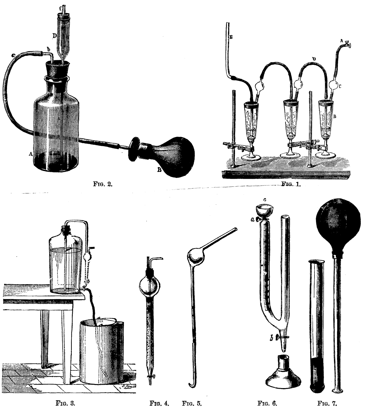
APPARATUS FOR ESTIMATING THE CARBONIC ACID OF THE AIR. 3.—Bertin-Sans Apparatus. FIG. 4.—Bubbling Glass. FIG. 5.—Pipette. FIG. 6.—Arrangement of the U-shaped Tube. FIG. 7.—Wolpert's Apparatus.
Hygienists have for some years striven to obtain some very simple apparatus (rather as an indicator than an analytical instrument) that should permit it to be quickly ascertained whether the degree of impurity of a place was incompatible with health, and in what proportion it was so. It is from such efforts that have resulted the processes of Messrs. Smith. Lunge, Bertin-Sans, and the apparatus of Prof. Wolpert (Fig. 7).
It is of the highest interest to ascertain the proportion of carbonic acid in the air, and especially in that of inhabited places, since up to the present this is the best means of finding out how much the air that we are breathing is polluted, and whether there is sufficient ventilation or not. Experiment has, in fact, demonstrated that carbonic acid increases in the air of inhabited rooms in the same way as do those organic matters which are difficult of direct estimation. Although a few ten-thousandths more of carbonic acid in our air cannot of themselves endanger us, yet they have on another hand a baneful significance, and, indeed, the majority of hygienists will not tolerate more than six ten-millionths of this element in the air of dwellings, and some of them not more than five ten-millionths.
Carbonic acid readily betrays its presence through solutions of the alkaline earths such as baryta and chalk, in which its passage produces an insoluble carbonate, and consequently makes the liquid turbid. If, then, one has prepared a solution of baryta or lime, of which a certain volume is made turbid by the passage of a likewise known volume of CO2, it will be easy to ascertain how much CO2 a certain air contains, from the volume of the latter that it will be necessary to pass through the basic solution in order to obtain the amount of turbidity that has been taken as a standard. The problem consists in determining the minimum of air required to make the known solution turbid. Hence the name "minimetric estimation," that has been given to this process. Prof. Lescoeur has had the goodness to construct for me a Smith's minimetric apparatus (Fig. 2) with the ingenious improvements that have been made in it by Mr. Fischli, assistant to Prof. Weil, of Zurich. I have employed it frequently, and I use it every year in my lectures. I find it very practical, provided one has got accustomed to using it. It is, at all events, of much simpler manipulation than that of Bertin-Sans, although the accuracy of the latter may be greater (Figs. 3, 4, 5, and 6). But it certainly has more than one defect, and some of the faults that have been found with it are quite serious. The worst of these consists in the difficulty of catching the exact moment at which the turbidity of the basic liquid is at the proper point for arresting the operation. In addition to this capital defect, it is regrettable that it is necessary to shake the flask that contains the solution after every insufflation of air, and also that the play of the valves soon becomes imperfect. Finally, Mr. Wolpert rightly sees one serious drawback to the use of baryta in an apparatus that has to be employed in schools, among children, and that is that this substance is poisonous. This gentleman therefore replaces the solution of baryta by water saturated with lime, which costs almost nothing, and the preparation of which is exceedingly simple. Moreover, it is a harmless agent.
The apparatus consists of two parts. The first of these is a glass tube closed at one end, and 12 cm. in length by 12 mm. in diameter. Its bottom is of porcelain, and bears on its inner surface the date 1882 in black characters. Above, and at the level that corresponds to a volume of three cubic centimeters, there is a black line which serves as an invariable datum point. A rubber bulb of twenty-eight cubic centimeters capacity is fixed to a tube which reaches its bottom, and is flanged at the other extremity (Fig. 7).
The operation is as follows:
The saturated, but limpid, solution of lime is poured into the first tube up to the black mark, the tube of the air bulb is introduced into the lime water in such a way that its orifice shall be in perfect contact with the bottom of the other tube, and then, while the bulb is held between the fore and middle fingers of the upturned hand, one presses slowly with the thumb upon its bottom so as to expel all the air that it contains. This air enters the lime-water bubble by bubble. After this the tube is removed from the water, and the bulb is allowed to fill with air, and the same maneuver is again gone through with. This is repeated until the figures 1882, looked at from above, cease to be clearly visible, and disappear entirely after the contents of the tube have been vigorously shaken.
The measures are such that the turbidity supervenes at once if the air in the bulb contains twenty thousandths of CO2. If it becomes necessary to inject the contents of the bulb into the water twice, it is clear that the proportion is only ten thousandths; and if it requires ten injections the air contains ten times less CO2 than that having twenty thousandths, or only two per cent. A table that accompanies the apparatus has been constructed upon this basis, and does away with the necessity of making calculations.
An air that contained ten thousandths of CO2, or even five, would be almost as deleterious, in my opinion, as one of two per cent. It is of no account, then, to know the proportions intermediate to these round numbers. Yet it is possible, if the case requires it, to obtain an indication between two consecutive figures of the scale by means of another bulb whose capacity is only half that of the preceding. Thus, two injections of the large bulb, followed by one of the small, or two and a half injections, correspond to a richness of 8 thousandths of CO2; and 5½ to 3.6 thousandths. This half-bulb serves likewise for another purpose. From the moment that the large bulb makes the lime-water turbid with an air containing two per cent. of CO2, it is clear that the small one can cause the same turbidity only with air twice richer in CO2, i.e., of four per cent.
This apparatus, although it makes no pretensions to extreme accuracy, is capable of giving valuable information. The table that accompanies it is arranged for a temperature of 17° and a pressure of 740 mm. But different meteorological conditions do not materially alter the results. Thus, with 10° less it would require thirty-one injections instead of thirty, and CO2 would be 0.64 per 1,000 instead of 0.66; and with 10° more, thirty injections instead of thirty one.
The apparatus is contained in a box that likewise holds a bottle of lime-water sufficient for a dozen analyses, the table of proportions of CO2, and the apparatus for cleaning the tubes. The entire affair is small enough to be carried in the pocket.—J. Arnould, in Science et Nature.
[NATURE.]
Knowing how much Nature is read by all the naturalists of the world, I send these few lines, which I hope will be of some interest.
The Italian R.N. corvette Vettor Pisani left Italy in April, 1882, for a voyage round the world with the ordinary commission of a man-of-war. The Minister of Marine, wishing to obtain scientific results, gave orders to form, when possible, a marine zoological collection, and to carry on surveying, deep-sea soundings, and abyssal thermometrical measurements. The officers of the ship received their different scientific charges, and Prof. Dohrn, director of the Zoological Station at Naples, gave to the writer necessary instructions for collecting and preserving sea animals.
At the end of 1882 the Vettor Pisani visited the Straits of Magellan, the Patagonian Channels, and Chonos and Chiloe islands; we surveyed the Darwin Channel, and following Dr. Cuningham's work (who visited these places on board H.M.S. Nassau), we made a numerous collection of sea animals by dredging and fishing along the coasts.
While fishing for a big shark in the Gulf of Panama during the stay of our ship in Taboga Island, one day in February, with a dead clam, we saw several great sharks some miles from our anchorage. In a short time several boats with natives went to sea, accompanied by two of the Vettor Pisani's boats.
Having wounded one of these animals in the lateral part of the belly, we held him with lines fixed to the spears; he then began to describe a very narrow curve, and irritated by the cries of the people that were in the boats, ran off with a moderate velocity. To the first boat, which held the lines just mentioned, the other boats were fastened, and it was a rather strange emotion to feel ourselves towed by the monster for more than three hours with a velocity that proved to be two miles per hour. One of the boats was filled with water. At last the animal was tired by the great loss of blood, and the boats assembled to haul in the lines and tow the shark on shore.
With much difficulty the nine boats towed the animal alongside the Vettor Pisani to have him hoisted on board, but it was impossible on account of his colossal dimensions. But as it was high water we went toward a sand beach with the animal, and we had him safely stranded at night.
With much care were inspected the mouth, the nostrils, the ears, and all the body, but no parasite was found. The eyes were taken out and prepared for histological study. The set of teeth was all covered by a membrane that surrounded internally the lips; the teeth are very little, and almost in a rudimental state. The mouth, instead of opening in the inferior part of the head, as in common sharks, was at the extremity of the head; the jaws having the same bend.
Cutting the animal on one side of the backbone we met (1) a compact layer of white fat 20 centimeters deep; (2) the cartilaginous ribs covered with blood vessels; (3) a stratum of flabby, stringy, white muscle, 60 centimeters high, apparently in adipose degeneracy; (4) the stomach.
By each side of the backbone he had three chamferings, or flutings, that were distinguished by inflected interstices. The color of the back was brown with yellow spots that became close and small toward the head, so as to be like marble spots. The length of the shark was 8.90 m. from the mouth to the pinna caudalis extremity, the greatest circumference 6.50 m., and 2.50 m. the main diameter (the outline of the two projections is made for giving other dimensions).
The natives call the species Tintoreva, and the most aged of the village had only once before fished such an animal, but smaller. While the animal was on board we saw several Remora about a foot long drop from his mouth; it was proved that these fish lived fixed to the palate, and one of them was pulled off and kept in the zoological collection of the ship.
The Vettor Pisani has up the present visited Gibraltar, Cape Verde Islands, Pernambuco, Rio Janeiro, Monte Video, Valparaiso, many ports of Peru, Guayaquil, Panama, Galapagos Islands, and all the collections were up to this sent to the Zoological Station at Naples to be studied by the naturalists. By this time the ship left Callao for Honolulu, Manila, Hong Kong, and, as the Challenger had not crossed the Pacific Ocean in these directions, we made several soundings and deep-sea thermometrical measurements from Callao to Honolulu. Soundings are made with a steel wire (Thompson system) and a sounding-rod invented by J. Palumbo, captain of the ship. The thermometer employed is a Negretti and Zambra deep-sea thermometer, improved by Captain Maguaghi (director of the Italian R.N. Hydrographic Office).
With the thermometer wire has always been sent down a tow-net which opens and closes automatically, also invented by Captain Palumbo. This tow-net has brought up some little animals that I think are unknown.
G. CHIERCHIA.
Honolulu July 1.
The shark captured by the Vettor Pisani in the Gulf of Panama is Rhinodon typicus, probably the most gigantic fish in existence. Mr. Swinburne Ward, formerly commissioner of the Seychelles, has informed me that it attains to a length of 50 feet or more, which statement was afterward confirmed by Prof. E.P. Wright. Originally described by Sir A. Smith from a single specimen which was killed in the neighborhood of Cape Town, this species proved to be of not uncommon occurrence in the Seychelles Archipelago, where it is known by the name of "Chagrin." Quite recently Mr. Haly reported the capture of a specimen on the coast of Ceylon. Like other large sharks (Carcharodon rondeletii, Selache maxima, etc.), Rhinodon has a wide geographical range, and the fact of its occurrence on the Pacific coast of America, previously indicated by two sources, appears now to be fully established. T. Gill in 1865 described a large shark known in the Gulf of California by the name of "Tiburon ballenas" or whale-shark, as a distinct genus—Micristodus punctatus—which, in my opinion, is the same fish. And finally, Prof. W. Nation examined in 1878 a specimen captured at Callao. Of this specimen we possess in the British Museum a portion of the dental plate. The teeth differ in no respect from those of a Seychelles Chagrin; they are conical, sharply pointed, recurved, with the base of attachment swollen. Making no more than due allowance for such variations in the descriptions by different observers as are unavoidable in accounts of huge creatures examined by some in a fresh, by others in a preserved, state, we find the principal characteristics identical in all these accounts, viz.: the form of the body, head, and snout, relative measurements, position of mouth, nostrils, and eyes, dentition, peculiar ridges on the side of the trunk and tail, coloration, etc. I have only to add that this shark is stated to be of mild disposition and quite harmless. Indeed, the minute size of its teeth has led to the belief in the Seychelles that it is a herbivorous fish, which, however, is not probable.
ALBERT GUNTHER.
Natural History Museum, July 30.
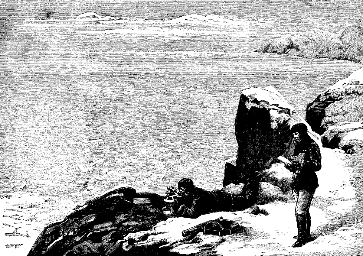
THE GREELY ARCTIC EXPEDITION.—THE FARTHEST POINT NORTH.
Some account has been given of the American Meteorological Expedition, commanded by Lieutenant, now Major, Greely, of the United States Army, in the farthest north channels, beyond Smith Sound, that part of the Arctic regions where the British Polar expedition, in May, 1876, penetrated to within four hundred geographical miles of the North Pole. The American expedition, in 1883, succeeded in getting four miles beyond, this being effected by a sledge party traveling over the snow from Fort Conger, the name they had given to their huts erected on the western shore near Discovery Cove, in Lady Franklin Sound. The farthest point reached, on May 18, was in latitude 83 deg. 24 min. N.; longitude 40 deg. 46 min. W., on the Greenland coast. The sledge party was commanded by Lieutenant Lockwood, and the following particulars are supplied by Sergeant Brainerd, who accompanied Lieutenant Lockwood on the expedition. During their sojourn in the Arctic regions the men were allowed to grow the full beard, except under the mouth, where it was clipped short. They wore knitted mittens, and over these heavy seal-skin mittens were drawn, connected by a tanned seal-skin string that passed over the neck, to hold them when the hands were slipped out. Large tanned leather pockets were fastened outside the jackets, and in very severe weather jerseys were sometimes worn over the jackets for greater protection against the intense cold. On the sledge journeys the dogs were harnessed in a fan-shaped group to the traces, and were never run tandem. In traveling, the men were accustomed to hold on to the back of the sledge, never going in front of the team, and often took off their heavy overcoats and threw them on the load. When taking observations with the sextant, Lieutenant Lockwood generally reclined on the snow, while Sergeant Brainerd called time and made notes, as shown in our illustration. When further progress northward was barred by open water, and the party almost miraculously escaped drifting into the Polar sea, Lieutenant Lockwood erected, at the highest point of latitude reached by civilized man, a pyramidal-shaped cache of stones, six feet square at the base, and eight or nine feet high. In a little chamber about a foot square half-way to the apex, and extending to the center of the pile, he placed a self-recording spirit thermometer, a small tin cylinder containing records of the expedition, and then sealed up the aperture with a closely fitting stone. The cache was surmounted with a small American flag made by Mrs. Greely, but there were only thirteen stars, the number of the old revolutionary flag. From the summit of Lockwood Island, the scene presented in our illustration, 2,000 feet above the sea, Lieutenant Lockwood was unable to make out any land to the north or the northwest. "The awful panorama of the Arctic which their elevation spread out before them made a profound impression upon the explorers. The exultation which was natural to the achievement which they found they had accomplished was tempered by the reflections inspired by the sublime desolation of that stern and silent coast and the menace of its unbroken solitude. Beyond to the eastward was the interminable defiance of the unexplored coast—black, cold, and repellent. Below them lay the Arctic Ocean, buried beneath frozen chaos. No words can describe the confusion of this sea of ice—the hopeless asperity of it, the weariness of its torn and tortured surface. Only at the remote horizon did distance and the fallen snow mitigate its roughness and soften its outlines; and beyond it, in the yet unattainable recesses of the great circle, they looked toward the Pole itself. It was a wonderful sight, never to be forgotten, and in some degree a realization of the picture that astronomers conjure to themselves when the moon is nearly full, and they look down into the great plain which is called the Ocean of Storms, and watch the shadows of sterile and airless peaks follow a slow procession across its silver surface."—Illustrated London News.
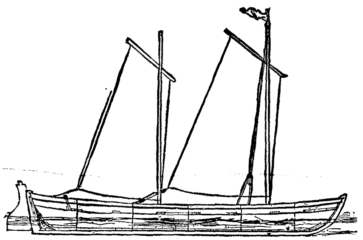
WHALER GIG FOR THE NILE.
As soon as the authorities had finally made up their minds to send a flotilla of boats to Cairo for the relief of Khartoum, not a moment was lost in issuing orders to the different shipbuilding contractors for the completion, with the utmost dispatch, of the 400 "whaler-gigs" for service on the Nile. They are light-looking boats, built of white pine, and weigh each about 920 lb., that is without the gear, and are supposed to carry four tons of provisions, ammunition, and camp appliances, the food being sufficient for 100 days. The crew will number twelve men, soldiers and sailors, the former rowing, while the latter (two) will attend the helm. Each boat will be fitted with two lug sails, which can be worked reefed, so as to permit an awning to be fitted underneath for protection to the men from the sun. As is well known, the wind blows for two or three months alternately up and down the Nile, and the authorities expect the flotilla will have the advantage of a fair wind astern for four or five days at the least. On approaching the Cataracts, the boats will be transported on wooden rollers over the sand to the next level for relaunching.
Believing that any ideas relating to this matter will be of some interest to your readers in this heavily-timbered region, I therefore propose giving you my opinion and conclusions arrived at after having experimented upon the cutting and use of timber for various purposes for a number of years here upon the Pacific coast.
This, we are all well aware, is a very important question, and one very difficult to answer, since it requires observation and experiment through a course of many years to arrive at any definite conclusion; and it is a question too upon which even at the present day there exists a great difference of opinion among men who, being engaged in the lumber business, are thereby the better qualified to form an opinion.
Many articles have been published in the various papers of the country upon this question for the past thirty years, but in all cases an opinion only has been given, which, at the present day, such is the advance and higher development of the intellectual faculties of man, that a mere opinion upon any question without sufficient and substantial reasons to back it is of little value.
My object in writing this is not simply to give an opinion, but how and the methods used by which I adopted such conclusions, as well also as the reasons why timber is more durable and better when cut at a certain season of the year than when cut at any other.
In the course of my investigations of this question for the past thirty years, I have asked the opinion of a great many persons who have been engaged in the lumber business in various States of the Union, from Maine to Wisconsin, and they all agree upon one point, viz., that the winter time is the proper time for cutting timber, although none has ever been able to give a reason why, only the fact that such was the case, and therefore drawing the inference that it was the proper time when timber should be cut; and so it is, for one reason only, however, and that is the convenience for handling or moving timber upon the snow and ice.
It was while engaged in the business of mining in the mountains of California in early days, and having occasion to work often among timber, in removing stumps, etc., it was while so engaged that I noticed one peculiar fact, which was this—that the stumps of some trees which had been cut but two or three years had decayed, while others of the same size and variety of pine which had been cut the same year were as sound and firm as when first cut. This seemed strange to me, and I found upon inquiry of old lumbermen who had worked among timber all their lives, that it was strange to them also, and they could offer no explanation; and it was the investigation of this singular fact that led me to experiment further upon the problem of cutting timber.
It was not, however, until many years after, and when engaged in clearing land for farming purposes, that I made the discovery why some stumps should decay sooner than others of the same size and variety, even when cut a few months afterward.
I had occasion to clear several acres of land which was covered with a very dense growth of young pines from two to six inches in diameter (this work for certain reasons is usually done in the winter). The young trees, not being suitable for fuel, are thrown into piles and burned upon the ground. Such land, therefore, on account of the stumps is very difficult to plow, as the stumps do not decay for three or four years, while most of the larger ones remain sound even longer.
But, for the purpose of experimenting, I cleaned a few acres of ground in the spring, cutting them in May and June. I trimmed the poles, leaving them upon the ground, and when seasoned hauled them to the house for fuel, and found that for cooking or heating purposes they were almost equal to oak; and it was my practice for many years afterward to cut these young pines in May or June for winter fuel.
I found also that the stumps, instead of remaining sound for any length of time, decayed so quickly that they could all be plowed up the following spring.
From which facts I draw these conclusions: that if in the cutting of timber the main object is to preserve the stumps, cut your trees in the fall or winter; but if the value of the timber is any consideration, cut your trees in the spring after the sap has ascended the tree, but before any growth has taken place or new wood has been formed.
I experimented for many years also in the cutting of timber for fencing, fence posts, etc., and with the same results. Those which were cut in the spring and set after being seasoned were the most durable, such timber being much lighter, tougher, and in all respects better for all variety of purposes.
Having given some little idea of the manner in which I experimented, and the conclusions arrived at as to the proper time when timber should be cut, I now propose to give what are, in my opinion, the reasons why timber cut in early summer is much better, being lighter, tougher and more durable than if cut at any other time. Therefore, in order to do this it is necessary first to explain the nature and value of the sap and the growth of a tree.
We find it to be the general opinion at present, as it perhaps has always been among lumbermen and those who work among timber, that the sap of a tree is an evil which must be avoided if possible, for it is this which causes decay and destroys the life and good qualities of all wood when allowed to remain in it for an unusual length of time, but that this is a mistaken idea I will endeavor to show, not that the decay is due to the sap, but to the time when the tree was felled.
We find by experiment in evaporating a quantity of sap of the pine, that it is water holding in solution a substance of a gummy nature, being composed of albumen and other elementary matters, which is deposited within the pores of the wood from the new growth of the tree; that these substances in solution, which constitute the sap, and which promote the growth of the tree, should have a tendency to cause decay of the wood is an impossibility. The injury results from the water only, and the improper time of felling the tree.
Of the process in which the sap promotes the growth of the tree, the scientist informs us that it is extracted from the soil, and flows up through the pores of the wood of the tree, where it is deposited upon the fiber, and by a peculiar process of nature the albumen forms new cells, which in process of formation crowd and push out from the center, thus constituting the growth of the tree in all directions from center to circumference. Consequently this new growth of wood, being composed principally of albumen, is of a soft, spongy nature, and under the proper conditions will decay very rapidly, which can be easily demonstrated by experiment.
Hence, we must infer that the proper time for felling the tree is when the conditions are such that the rapid decay of a new growth of wood is impossible; and this I have found by experiment to be in early summer, after the sap has ascended the tree, but before any new growth of wood has been formed. The new growth of the previous season is now well matured, has become hard and firm, and will not decay. On the contrary, the tree being cut when such new growth has not well matured, decay soon takes place, and the value of the timber is destroyed. The effect of this cutting and use of timber under the wrong conditions can be seen all around us. In the timbers of the bridges, in the trestlework and ties of railroads and in the piling of the wharves will be found portions showing rapid decay, while other portions are yet firm and in sound condition.
Much more might be said in the explanation of this subject, but not wishing to extend the subject to an improper length, I will close. I would, however, say in conclusion that persons who have the opportunities and the inclination can verify the truth of a portion, at least, of what I have stated, in a simple manner and in a short time; for instance, by cutting two or three young fir or spruce saplings, say about six inches in diameter, mark them when cut, and also mark the stumps by driving pegs marked to correspond with the trees. Continue this monthly for the space of about one year, and note the difference in the wood, which should be left out and exposed to the weather until seasoned.
C.W. HASKINS.
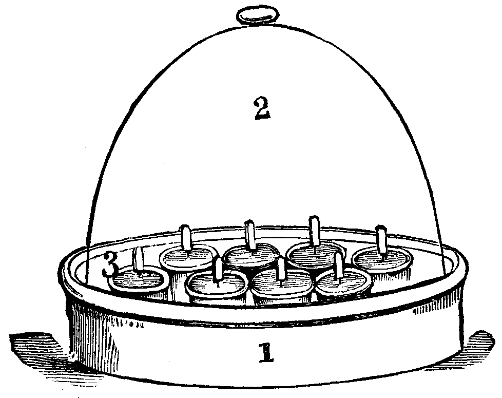
1, PAN; 2, BELL GLASS; 3, SMALL POTS AND LABELS.
This plan, of which I give a sketch, has been in use by myself for many years, and most successfully. I have at various times given it to growers, but still I hear of difficulties. Procure a good sized bell-glass and an earthenware pan without any holes for drainage. Prepare a number of small pots, all filled for sowing, place them inside the pan, and fit the glass over them, so that it takes all in easily. Take these filled small pots out of the pan, place them on the ground, and well water them with boiling water to destroy all animal and vegetable life, and allow them to get perfectly cold; use a fine rose. Then taking each small pot separately, sow the spores on the surface and label them; do this with the whole number, and then place them in the pan under the bell-glass. This had better be done in a room, so that nothing foreign can grow inside. Having arranged the pots and placed the glass over them, and which should fit down upon the pan with ease, take a clean sponge, and tearing it up pack the pieces round the outside of the glass, and touching the inner side of the pan all round. Water this with cold water, so that the sponge is saturated. Do this whenever required, and always use water that has been boiled. At the end of six weeks or so the prothallus will perhaps appear, certainly in a week or two more; perhaps from unforeseen circumstances not for three months. Slowly these will begin to show themselves as young ferns, and most interesting it is to watch the results. As the ferns are gradually increasing in size pass a small piece of slate under the edge of the bell-glass to admit air, and do this by very careful degrees, allowing more and more air to reach them. Never water overhead until the seedlings are acclimated and have perfect form as ferns, and even then water at the edges of the pots. In due time carefully prick out, and the task so interesting to watch is performed.—The Garden.
Nearly a century ago, Vaucher, the celebrated Genevan botanist, described a fresh water filamentous alga which he named Ectosperma geminata, with a correctness that appears truly remarkable when the imperfect means of observation at his command are taken into consideration. His pupil, De Candolle, who afterward became so eminent a worker in the same field, when preparing his "Flora of France," in 1805, proposed the name of Vaucheria for the genus, in commemoration of the meritorious work of its first investigator. On March 12, 1826, Unger made the first recorded observation of the formation and liberation of the terminal or non-sexual spores of this plant. Hassall, the able English botanist, made it the subject of extended study while preparing his fine work entitled "A History of the British Fresh Water Algæ," published in 1845. He has given us a very graphic description of the phenomenon first observed by Unger. In 1856 Pringsheim described the true sexual propagation by oospores, with such minuteness and accuracy that our knowledge of the plant can scarcely be said to have essentially increased since that time.
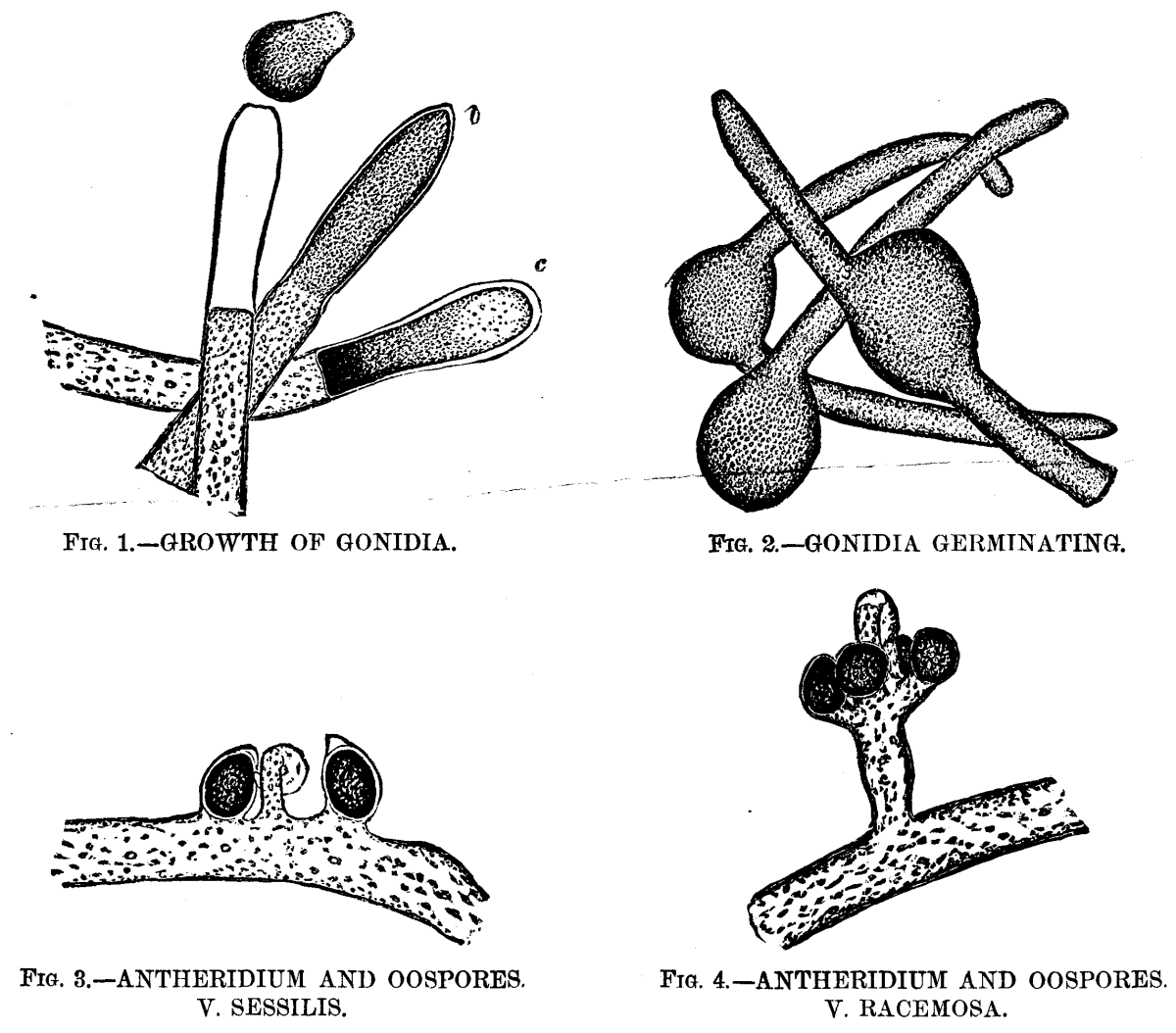
GROWTH OF THE ALGA, VAUCHERIA, UNDER THE MICROSCOPE.
Vaucheria has two or three rather doubtful marine species assigned to it by Harvey, but the fresh water forms are by far the more numerous, and it is to some of these I would call your attention for a few moments this evening. The plant grows in densely interwoven tufts, these being of a vivid green color, while the plant is in the actively vegetative condition, changing to a duller tint as it advances to maturity. Its habitat (with the exceptions above noted) is in freshwater—usually in ditches or slowly running streams. I have found it at pretty much all seasons of the year, in the stretch of boggy ground in the Presidio, bordering the road to Fort Point. The filaments attain a length of several inches when fully developed, and are of an average diameter of 1/250 (0.004) inch. They branch but sparingly, or not at all, and are characterized by consisting of a single long tube or cell, not divided by septa, as in the case of the great majority of the filamentous algæ. These tubular filaments are composed of a nearly transparent cellulose wall, including an inner layer thickly studded with bright green granules of chlorophyl. This inner layer is ordinarily not noticeable, but it retracts from the outer envelope when subjected to the action of certain reagents, or when immersed in a fluid differing in density from water, and it then becomes distinctly visible, as may be seen in the engraving (Fig. 1). The plant grows rapidly and is endowed with much vitality, for it resists changes of temperature to a remarkable degree. Vaucheria affords a choice hunting ground to the microscopist, for its tangled masses are the home of numberless infusoria, rotifers, and the minuter crustacea, while the filaments more advanced in age are usually thickly incrusted with diatoms. Here, too, is a favorite haunt of the beautiful zoophytes, Hydra vividis and H. vulgaris, whose delicate tentacles may be seen gracefully waving in nearly every gathering.
After the plant has attained a certain stage in its growth, if it be attentively watched, a marked change will be observed near the ends of the filaments. The chlorophyl appears to assume a darker hue, and the granules become more densely crowded. This appearance increases until the extremity of the tube appears almost swollen. Soon the densely congregated granules at the extreme end will be seen to separate from the endochrome of the filament, a clear space sometimes, but not always, marking the point of division. Here a septum or membrane appears, thus forming a cell whose length is about three or four times its width, and whose walls completely inclose the dark green mass of crowded granules (Fig. 1, b). These contents are now gradually forming themselves into the spore or "gonidium," as Carpenter calls it, in distinction from the true sexual spores, which he terms "oospores." At the extreme end of the filament (which is obtusely conical in shape) the chlorophyl grains retract from the old cellulose wall, leaving a very evident clear space. In a less noticeable degree, this is also the case in the other parts of the circumference of the cell, and, apparently, the granular contents have secreted a separate envelope entirely distinct from the parent filament. The grand climax is now rapidly approaching. The contents of the cell near its base are now so densely clustered as to appear nearly black (Fig. 1, c), while the upper half is of a much lighter hue and the separate granules are there easily distinguished, and, if very closely watched, show an almost imperceptible motion. The old cellulose wall shows signs of great tension, its conical extremity rounding out under the slowly increasing pressure from within. Suddenly it gives way at the apex. At the same instant, the inclosed gonidium (for it is now seen to be fully formed) acquires a rotary motion, at first slow, but gradually increasing until it has gained considerable velocity. Its upper portion is slowly twisted through the opening in the apex of the parent wall, the granular contents of the lower end flowing into the extruded portion in a manner reminding one of the flow of protoplasm in a living amoeba. The old cell wall seems to offer considerable resistance to the escape of the gonidium, for the latter, which displays remarkable elasticity, is pinched nearly in two while forcing its way through, assuming an hour glass shape when about half out. The rapid rotation of the spore continues during the process of emerging, and after about a minute it has fully freed itself (Fig 1, a). It immediately assumes the form of an ellipse or oval, and darts off with great speed, revolving on its major axis as it does so. Its contents are nearly all massed in the posterior half, the comparatively clear portion invariably pointing in advance. When it meets an obstacle, it partially flattens itself against it, then turns aside and spins off in a new direction. This erratic motion is continued for usually seven or eight minutes. The longest duration I have yet observed was a little over nine and one-half minutes. Hassall records a case where it continued for nineteen minutes. The time, however, varies greatly, as in some cases the motion ceases almost as soon as the spore is liberated, while in open water, unretarded by the cover glass or other obstacles, its movements have been seen to continue for over two hours.
The motile force is imparted to the gonidium by dense rows of waving cilia with which it is completely surrounded. Owing to their rapid vibration, it is almost impossible to distinguish them while the spore is in active motion, but their effect is very plainly seen on adding colored pigment particles to the water. By subjecting the cilia to the action of iodine, their motion is arrested, they are stained brown, and become very plainly visible.
After the gonidium comes gradually to a rest its cilia soon disappear, it becomes perfectly globular in shape, the inclosed granules distribute themselves evenly throughout its interior, and after a few hours it germinates by throwing out one, two, or sometimes three tubular prolongations, which become precisely like the parent filament (Fig 2).
Eminent English authorities have advanced the theory that the ciliated gonidium of Vaucheria is in reality a densely crowded aggregation of biciliated zoospores, similar to those found in many other confervoid algæ. Although this has by no means been proved, yet I cannot help calling the attention of the members of this society to a fact which I think strongly bears out the said theory: While watching a gathering of Vaucheria one morning when the plant was in the gonidia-forming condition (which is usually assumed a few hours after daybreak), I observed one filament, near the end of which a septum had formed precisely as in the case of ordinary filaments about to develop a spore. But, instead of the terminal cell being filled with the usual densely crowded cluster of dark green granules constituting the rapidly forming spore, it contained hundreds of actively moving, nearly transparent zoospores, and nothing else. Not a single chlorophyl granule was to be seen. It is also to be noted as a significant fact, that the cellulose wall was intact at the apex, instead of showing the opening through which in ordinary cases the gonidium escapes. It would seem to be a reasonable inference, I think, based upon the theory above stated, that in this case the newly formed gonidium, unable to escape from its prison by reason of the abnormal strength of the cell wall, became after a while resolved into its component zoospores.
I very much regret that my descriptive powers are not equal to conveying a sufficient idea of the intensely absorbing interest possessed by this wonderful process of spore formation. I shall never forget the bright sunny morning when for the first time I witnessed the entire process under the microscope, and for over four hours scarcely moved my eyes from the tube. To a thoughtful observer I doubt if there is anything in the whole range of microscopy to exceed this phenomenon in point of startling interest. No wonder that its first observer published his researches under the caption of "The Plant at the Moment of becoming an Animal."
The process of spore formation just described, it will be seen, is entirely non-sexual, being simply a vegetative process, analogous to the budding of higher plants, and the fission of some of the lower plants and animals. Vaucheria has, however, a second and far higher mode of reproduction, viz., by means of fertilized cells, the true oospores, which, lying dormant as resting spores during the winter, are endowed with new life by the rejuvenating influences of spring. Their formation may be briefly described as follows:
When Vaucheria has reached the proper stage in its life cycle, slight swellings appear here and there on the sides of the filament. Each of these slowly develops into a shape resembling a strongly curved horn. This becomes the organ termed the antheridium, from its analogy in function to the anther of flowering plants. While this is in process of growth, peculiar oval capsules or sporangia (usually 2 to 5 in number) are formed in close proximity to the antheridium. In some species both these organs are sessile on the main filament, in others they appear on a short pedicel (Figs. 3 and 4). The upper part of the antheridium becomes separated from the parent stem by a septum, and its contents are converted into ciliated motile antherozoids. The adjacent sporangia also become cut off by septa, and the investing membrane, when mature, opens: it a beak-like prolongation, thus permitting the inclosed densely congregated green granules to be penetrated by the antherozoids which swarm from the antheridium at the same time. After being thus fertilized the contents of the sporangium acquire a peculiar oily appearance, of a beautiful emerald color, an exceedingly tough but transparent envelope is secreted, and thus is constituted the fully developed oospore, the beginner of a new generation of the plant. After the production of this oospore the parent filament gradually loses its vitality and slowly decays.
The spore being thus liberated, sinks to the bottom. Its brilliant hue has faded and changed to a reddish brown, but after a rest of about three months (according to Pringsheim, who seems to be the only one who has ever followed the process of oospore formation entirely through), the spore suddenly assumes its original vivid hue and germinates into a young Vaucheria.
This concludes the account of my very imperfect attempt to trace the life history of a lowly plant. Its study has been to me a source of ever increasing pleasure, and has again demonstrated how our favorite instrument reveals phenomena of most absorbing interest in directions where the unaided eye finds but little promise. In walking along the banks of the little stream, where, half concealed by more pretentious plants, our humble Vaucheria grows, the average passer by, if he notices it at all, sees but a tangled tuft of dark green "scum." Yet, when this is examined under the magic tube, a crystal cylinder, closely set with sparkling emeralds, is revealed. And although so transparent, so apparently simple in structure that it does not seem possible for even the finest details to escape our search, yet almost as we watch it mystic changes appear. We see the bright green granules, impelled by an unseen force, separate and rearrange themselves in new formations. Strange outgrowths from the parent filament appear. The strange power we call "life," doubly mysterious when manifested in an organism so simple as this, so open to our search, seems to challenge us to discover its secret, and, armed with our glittering lenses and our flashing stands of exquisite workmanship, we search intently, but in vain. And yet not in vain, for we are more than recompensed by the wondrous revelations beheld and the unalloyed pleasures enjoyed, through the study of even the unpretentious Vaucheria.
The amplification of the objects in the engravings is about 80 diameters.
[1]LAURUS CAMPHORA, or "kusunoki," as it is called in Japan, grows mainly in those provinces in the islands Shikobu and Kinshin, which have the southern sea coast. It also grows abundantly in the province of Kishu.
The amount of camphor varies according to the age of the tree. That of a hundred years old is tolerably rich in camphor. In order to extract the camphor, such a tree is selected; the trunk and large stems are cut into small pieces, and subjected to distillation with steam.
An iron boiler of 3 feet in diameter is placed over a small furnace, the boiler being provided with an iron flange at the top. Over this flange a wooden tub is placed, which is somewhat narrowed at the top, being 1 foot 6 inches in the upper, and 2 feet 10 inches in the lower diameter, and 4 feet in height. The tub has a false bottom for the passage of steam from the boiler beneath. The upper part of the tub is connected with a condensing apparatus by means of a wooden or bamboo pipe. The condenser is a flat rectangular wooden vessel, which is surrounded with another one containing cold water. Over the first is placed still another trough of the same dimensions, into which water is supplied to cool the vessel at the top. After the first trough has been filled with water, the latter flows into the next by means of a small pipe attached to it. In order to expose a large surface to the vapors, the condensing trough is fitted internally with a number of vertical partitions, which are open at alternate ends, so that the vapors may travel along the partitions in the trough from one end to the other. The boiler is filled with water, and 120 kilogrammes of chopped pieces of wood are introduced into the tub, which is then closed with a cover, cemented with clay, so as to make it air-tight. Firing is then begun; the steam passes into the tub, and thus carries the vapors of camphor and oil into the condenser, in which the camphor solidifies, and is mixed with the oil and condensed water. After twenty-four hours the charge is taken out from the tub, and new pieces of the wood are introduced, and distillation is conducted as before. The water in the boiler must be supplied from time to time. The exhausted wood is dried and used as fuel. The camphor and oil accumulated in the trough are taken out in five or ten days, and they are separated from each other by filtration. The yield of the camphor and oil varies greatly in different seasons. Thus much more solid camphor is obtained in winter than in summer, while the reverse is the case with the oil. In summer, from 120 kilogrammes of the wood 2.4 kilogrammes, or 2 per cent. of the solid camphor are obtained in one day, while in winter, from the same amount of the wood, 3 kilogrammes, or 2.5 per cent., of camphor are obtainable at the same time.
The amount of the oil obtained in ten days, i.e., from 10 charges or 1,200 kilogrammes of the wood, in summer is about 18 liters, while in winter it amounts only to 5-7 liters. The price of the solid camphor is at present about 1s. 1d. per kilo.
The oil contains a considerable amount of camphor in solution, which is separated by a simple distillation and cooling. By this means about 20 per cent. of the camphor can be obtained from the oil. The author subjected the original oil to fractioned distillation, and examined different fractions separately. That part of the oil which distilled between 180°-185° O. was analyzed after repeated distillations. The following is the result:
| Found. | Calculated as C10H16O. |
|
|---|---|---|
| C = 78.87 | 78.95 | |
| H = 10.73 | 10.52 | |
| O = 10.40 | (by difference) | 10.52 |
The composition thus nearly agrees with that of the ordinary camphor.
The fraction between 178°-180° C., after three distillations, gave the following analytical result:
C = 86.95
H = 12.28
    —————
    99.23
It appears from this result that the body is a hydrocarbon. The vapor density was then determined by V. Meyer's apparatus, and was found to be 5.7 (air=1). The molecular weight of the compound is therefore 5.7 × 14.42 × 2 = 164.4, which gives
| H = (164.4 × 12.28)/100 = 20.18 | |
| or C12H20 | |
| C = (164.4 × 86.95)/100 = 11.81 |
Hence it is a hydrocarbon of the terpene series, having the general formula CnH2n-4. From the above experiments it seems to be probable that the camphor oil is a complicated mixture, consisting of hydrocarbons of terpene series, oxy-hydrocarbons isomeric with camphor, and other oxidized hydrocarbons.
The distinguishing property of the camphor oil, that it dissolves many resins, and mixes with drying oils, finds its application for the preparation of varnish. The author has succeeded in preparing various varnishes with the camphor oil, mixed with different resins and oils. Lampblack was also prepared by the author, by subjecting the camphor oil to incomplete combustion. In this way from 100 c.c. of the oil, about 13 grammes of soot of a very good quality were obtained. Soot or lampblack is a very important material in Japan for making inks, paints, etc. If the manufacture of lampblack from the cheap camphor oil is conducted on a large scale, it would no doubt be profitable. The following is the report on the amount of the annual production of camphor in the province of Tosa up to 1880:
    Amount of Camphor produced.   Total Cost.

1877.......... 504,000 kins.... 65,520 yen.
1878.......... 519,000   " .... 72,660  "
1879.......... 292,890   " .... 74,481  "
1880.......... 192,837   " .... 58,302  "

(1 yen = 2s. 9d.)
(1 kin = 1-1/3lb.)
[1]
McLeod's sunshine recorder consists of a camera fixed with its axis parallel to that of the earth, and with the lens northward. Opposite to the lens there is placed a round-bottomed flask, silvered inside. The solar rays reflected from this sphere pass through the lens, and act on the sensitive surface.
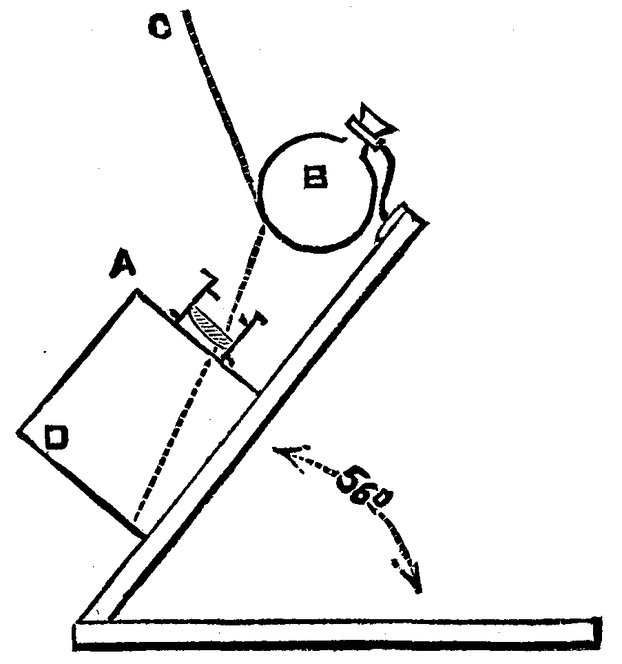
The construction of the instrument is illustrated by the subjoined cut, A being a camera supported at an inclination of 56 degrees with the horizon, and B the spherical flask silvered inside, while at D is placed the ferro-prussiate paper destined to receive the solar impression. The dotted line, C, may represent the direction of the central solar ray at one particular time, and it is easy to see how the sunlight reflected from the flask always passes through the lens. As the sun moves (apparently) in a circle round the flask, the image formed by the lens moves round on the sensitive paper, forming an arc of a circle.
Although it is obvious that any sensitive surface might be used in the McLeod sunshine recorder, the inventor prefers at present to use the ordinary ferro-prussiate paper as employed by engineers for copying tracings, as this paper can be kept for a considerable length of time without change, and the blue image is fixed by mere washing in water; another advantage is the circumstance that a scale or set of datum lines can be readily printed on the paper from an engraved block, and if the printed papers be made to register properly in the camera, the records obtained will show at a glance the time at which sunshine commenced and ceased.
Instead of specially silvering a flask inside, it will be found convenient to make use of one of the silvered globes which are sold as Christmas tree ornaments.
The sensitive fluid for preparing the ferro-prussiate paper is made as follows: One part by weight of ferricyanide of potassium (red prussiate) is dissolved in eight parts of water, and one part of ammonia-citrate of iron is added. This last addition must be made in the dark-room. A smooth-faced paper is now floated on the liquid and allowed to dry.—Photo. News.
In Boston, Mass., recently, at a point where two iron bridges, with stone abutments, are being built over the Boston and Albany Railroad tracks at Brookline Avenue, the main water pipe, which partially supplies the city with water, had to be raised, and while in that position a large stone which was being raised slipped upon the pipe and broke it. Immediately a stream of water fifteen feet high spurted out. Before the water could be shut off it had made a breach thirty feet long in the main line of track, so that the entire four tracks, sleepers, and roadbed at that point were washed completely away.
A catalogue, containing brief notices of many important scientific papers heretofore published in the SUPPLEMENT, may be had gratis at this office.
Sent by mail, postage prepaid, to subscribers in any part of the United States or Canada. Six dollars a year, sent, prepaid, to any foreign country.
All the back numbers of THE SUPPLEMENT, from the commencement, January 1, 1876, can be had. Price, 10 cents each.
All the back volumes of THE SUPPLEMENT can likewise be supplied. Two volumes are issued yearly. Price of each volume, $2.50, stitched in paper, or $3.50, bound in stiff covers.
COMBINED RATES—One copy of SCIENTIFIC AMERICAN and one copy of SCIENTIFIC AMERICAN SUPPLEMENT, one year, postpaid, $7.00.
A liberal discount to booksellers, news agents, and canvassers.
MUNN & CO., Publishers,
361 Broadway, New York, N.Y.
In connection with the Scientific American, Messrs. MUNN & Co. are Solicitors of American and Foreign Patents, have had 39 years' experience, and now have the largest establishment in the world. Patents are obtained on the best terms.
A special notice is made in the Scientific American of all Inventions patented through this Agency, with the name and residence of the Patentee. By the immense circulation thus given, public attention is directed to the merits of the new patent, and sales or introduction often easily effected.
Any person who has made a new discovery or invention can ascertain, free of charge, whether a patent can probably be obtained, by writing to MUNN & Co.
We also send free our Hand Book about the Patent Laws, Patents, Caveats. Trade Marks, their costs, and how procured, with hints for procuring advances on inventions. Address
MUNN & CO., 361 Broadway, New York.
Branch Office, cor. F and 7th Sts., Washington, D.C.
End of the Project Gutenberg EBook of Scientific American Supplement, No.
460, October 25, 1884, by Various

*** END OF THIS PROJECT GUTENBERG EBOOK  SCIENTIFIC AMERICAN 460 ***

***** This file should be named 11734-h.htm or 11734-h.zip *****
This and all associated files of various formats will be found in:
        https://www.gutenberg.org/1/1/7/3/11734/

Produced by Don Kretz, Juliet Sutherland, Charles Franks and the DP Team

Updated editions will replace the previous one--the old editions
will be renamed.

Creating the works from public domain print editions means that no
one owns a United States copyright in these works, so the Foundation
(and you!) can copy and distribute it in the United States without
permission and without paying copyright royalties.  Special rules,
set forth in the General Terms of Use part of this license, apply to
copying and distributing Project Gutenberg-tm electronic works to
protect the PROJECT GUTENBERG-tm concept and trademark.  Project
Gutenberg is a registered trademark, and may not be used if you
charge for the eBooks, unless you receive specific permission.  If you
do not charge anything for copies of this eBook, complying with the
rules is very easy.  You may use this eBook for nearly any purpose
such as creation of derivative works, reports, performances and
research.  They may be modified and printed and given away--you may do
practically ANYTHING with public domain eBooks.  Redistribution is
subject to the trademark license, especially commercial
redistribution.


*** START: FULL LICENSE ***

THE FULL PROJECT GUTENBERG LICENSE
PLEASE READ THIS BEFORE YOU DISTRIBUTE OR USE THIS WORK

To protect the Project Gutenberg-tm mission of promoting the free
distribution of electronic works, by using or distributing this work
(or any other work associated in any way with the phrase "Project
Gutenberg"), you agree to comply with all the terms of the Full Project
Gutenberg-tm License (available with this file or online at
https://gutenberg.org/license).


Section 1.  General Terms of Use and Redistributing Project Gutenberg-tm
electronic works

1.A.  By reading or using any part of this Project Gutenberg-tm
electronic work, you indicate that you have read, understand, agree to
and accept all the terms of this license and intellectual property
(trademark/copyright) agreement.  If you do not agree to abide by all
the terms of this agreement, you must cease using and return or destroy
all copies of Project Gutenberg-tm electronic works in your possession.
If you paid a fee for obtaining a copy of or access to a Project
Gutenberg-tm electronic work and you do not agree to be bound by the
terms of this agreement, you may obtain a refund from the person or
entity to whom you paid the fee as set forth in paragraph 1.E.8.

1.B.  "Project Gutenberg" is a registered trademark.  It may only be
used on or associated in any way with an electronic work by people who
agree to be bound by the terms of this agreement.  There are a few
things that you can do with most Project Gutenberg-tm electronic works
even without complying with the full terms of this agreement.  See
paragraph 1.C below.  There are a lot of things you can do with Project
Gutenberg-tm electronic works if you follow the terms of this agreement
and help preserve free future access to Project Gutenberg-tm electronic
works.  See paragraph 1.E below.

1.C.  The Project Gutenberg Literary Archive Foundation ("the Foundation"
or PGLAF), owns a compilation copyright in the collection of Project
Gutenberg-tm electronic works.  Nearly all the individual works in the
collection are in the public domain in the United States.  If an
individual work is in the public domain in the United States and you are
located in the United States, we do not claim a right to prevent you from
copying, distributing, performing, displaying or creating derivative
works based on the work as long as all references to Project Gutenberg
are removed.  Of course, we hope that you will support the Project
Gutenberg-tm mission of promoting free access to electronic works by
freely sharing Project Gutenberg-tm works in compliance with the terms of
this agreement for keeping the Project Gutenberg-tm name associated with
the work.  You can easily comply with the terms of this agreement by
keeping this work in the same format with its attached full Project
Gutenberg-tm License when you share it without charge with others.

1.D.  The copyright laws of the place where you are located also govern
what you can do with this work.  Copyright laws in most countries are in
a constant state of change.  If you are outside the United States, check
the laws of your country in addition to the terms of this agreement
before downloading, copying, displaying, performing, distributing or
creating derivative works based on this work or any other Project
Gutenberg-tm work.  The Foundation makes no representations concerning
the copyright status of any work in any country outside the United
States.

1.E.  Unless you have removed all references to Project Gutenberg:

1.E.1.  The following sentence, with active links to, or other immediate
access to, the full Project Gutenberg-tm License must appear prominently
whenever any copy of a Project Gutenberg-tm work (any work on which the
phrase "Project Gutenberg" appears, or with which the phrase "Project
Gutenberg" is associated) is accessed, displayed, performed, viewed,
copied or distributed:

This eBook is for the use of anyone anywhere at no cost and with
almost no restrictions whatsoever.  You may copy it, give it away or
re-use it under the terms of the Project Gutenberg License included
with this eBook or online at www.gutenberg.org

1.E.2.  If an individual Project Gutenberg-tm electronic work is derived
from the public domain (does not contain a notice indicating that it is
posted with permission of the copyright holder), the work can be copied
and distributed to anyone in the United States without paying any fees
or charges.  If you are redistributing or providing access to a work
with the phrase "Project Gutenberg" associated with or appearing on the
work, you must comply either with the requirements of paragraphs 1.E.1
through 1.E.7 or obtain permission for the use of the work and the
Project Gutenberg-tm trademark as set forth in paragraphs 1.E.8 or
1.E.9.

1.E.3.  If an individual Project Gutenberg-tm electronic work is posted
with the permission of the copyright holder, your use and distribution
must comply with both paragraphs 1.E.1 through 1.E.7 and any additional
terms imposed by the copyright holder.  Additional terms will be linked
to the Project Gutenberg-tm License for all works posted with the
permission of the copyright holder found at the beginning of this work.

1.E.4.  Do not unlink or detach or remove the full Project Gutenberg-tm
License terms from this work, or any files containing a part of this
work or any other work associated with Project Gutenberg-tm.

1.E.5.  Do not copy, display, perform, distribute or redistribute this
electronic work, or any part of this electronic work, without
prominently displaying the sentence set forth in paragraph 1.E.1 with
active links or immediate access to the full terms of the Project
Gutenberg-tm License.

1.E.6.  You may convert to and distribute this work in any binary,
compressed, marked up, nonproprietary or proprietary form, including any
word processing or hypertext form.  However, if you provide access to or
distribute copies of a Project Gutenberg-tm work in a format other than
"Plain Vanilla ASCII" or other format used in the official version
posted on the official Project Gutenberg-tm web site (www.gutenberg.org),
you must, at no additional cost, fee or expense to the user, provide a
copy, a means of exporting a copy, or a means of obtaining a copy upon
request, of the work in its original "Plain Vanilla ASCII" or other
form.  Any alternate format must include the full Project Gutenberg-tm
License as specified in paragraph 1.E.1.

1.E.7.  Do not charge a fee for access to, viewing, displaying,
performing, copying or distributing any Project Gutenberg-tm works
unless you comply with paragraph 1.E.8 or 1.E.9.

1.E.8.  You may charge a reasonable fee for copies of or providing
access to or distributing Project Gutenberg-tm electronic works provided
that

- You pay a royalty fee of 20% of the gross profits you derive from
     the use of Project Gutenberg-tm works calculated using the method
     you already use to calculate your applicable taxes.  The fee is
     owed to the owner of the Project Gutenberg-tm trademark, but he
     has agreed to donate royalties under this paragraph to the
     Project Gutenberg Literary Archive Foundation.  Royalty payments
     must be paid within 60 days following each date on which you
     prepare (or are legally required to prepare) your periodic tax
     returns.  Royalty payments should be clearly marked as such and
     sent to the Project Gutenberg Literary Archive Foundation at the
     address specified in Section 4, "Information about donations to
     the Project Gutenberg Literary Archive Foundation."

- You provide a full refund of any money paid by a user who notifies
     you in writing (or by e-mail) within 30 days of receipt that s/he
     does not agree to the terms of the full Project Gutenberg-tm
     License.  You must require such a user to return or
     destroy all copies of the works possessed in a physical medium
     and discontinue all use of and all access to other copies of
     Project Gutenberg-tm works.

- You provide, in accordance with paragraph 1.F.3, a full refund of any
     money paid for a work or a replacement copy, if a defect in the
     electronic work is discovered and reported to you within 90 days
     of receipt of the work.

- You comply with all other terms of this agreement for free
     distribution of Project Gutenberg-tm works.

1.E.9.  If you wish to charge a fee or distribute a Project Gutenberg-tm
electronic work or group of works on different terms than are set
forth in this agreement, you must obtain permission in writing from
both the Project Gutenberg Literary Archive Foundation and Michael
Hart, the owner of the Project Gutenberg-tm trademark.  Contact the
Foundation as set forth in Section 3 below.

1.F.

1.F.1.  Project Gutenberg volunteers and employees expend considerable
effort to identify, do copyright research on, transcribe and proofread
public domain works in creating the Project Gutenberg-tm
collection.  Despite these efforts, Project Gutenberg-tm electronic
works, and the medium on which they may be stored, may contain
"Defects," such as, but not limited to, incomplete, inaccurate or
corrupt data, transcription errors, a copyright or other intellectual
property infringement, a defective or damaged disk or other medium, a
computer virus, or computer codes that damage or cannot be read by
your equipment.

1.F.2.  LIMITED WARRANTY, DISCLAIMER OF DAMAGES - Except for the "Right
of Replacement or Refund" described in paragraph 1.F.3, the Project
Gutenberg Literary Archive Foundation, the owner of the Project
Gutenberg-tm trademark, and any other party distributing a Project
Gutenberg-tm electronic work under this agreement, disclaim all
liability to you for damages, costs and expenses, including legal
fees.  YOU AGREE THAT YOU HAVE NO REMEDIES FOR NEGLIGENCE, STRICT
LIABILITY, BREACH OF WARRANTY OR BREACH OF CONTRACT EXCEPT THOSE
PROVIDED IN PARAGRAPH F3.  YOU AGREE THAT THE FOUNDATION, THE
TRADEMARK OWNER, AND ANY DISTRIBUTOR UNDER THIS AGREEMENT WILL NOT BE
LIABLE TO YOU FOR ACTUAL, DIRECT, INDIRECT, CONSEQUENTIAL, PUNITIVE OR
INCIDENTAL DAMAGES EVEN IF YOU GIVE NOTICE OF THE POSSIBILITY OF SUCH
DAMAGE.

1.F.3.  LIMITED RIGHT OF REPLACEMENT OR REFUND - If you discover a
defect in this electronic work within 90 days of receiving it, you can
receive a refund of the money (if any) you paid for it by sending a
written explanation to the person you received the work from.  If you
received the work on a physical medium, you must return the medium with
your written explanation.  The person or entity that provided you with
the defective work may elect to provide a replacement copy in lieu of a
refund.  If you received the work electronically, the person or entity
providing it to you may choose to give you a second opportunity to
receive the work electronically in lieu of a refund.  If the second copy
is also defective, you may demand a refund in writing without further
opportunities to fix the problem.

1.F.4.  Except for the limited right of replacement or refund set forth
in paragraph 1.F.3, this work is provided to you 'AS-IS', WITH NO OTHER
WARRANTIES OF ANY KIND, EXPRESS OR IMPLIED, INCLUDING BUT NOT LIMITED TO
WARRANTIES OF MERCHANTIBILITY OR FITNESS FOR ANY PURPOSE.

1.F.5.  Some states do not allow disclaimers of certain implied
warranties or the exclusion or limitation of certain types of damages.
If any disclaimer or limitation set forth in this agreement violates the
law of the state applicable to this agreement, the agreement shall be
interpreted to make the maximum disclaimer or limitation permitted by
the applicable state law.  The invalidity or unenforceability of any
provision of this agreement shall not void the remaining provisions.

1.F.6.  INDEMNITY - You agree to indemnify and hold the Foundation, the
trademark owner, any agent or employee of the Foundation, anyone
providing copies of Project Gutenberg-tm electronic works in accordance
with this agreement, and any volunteers associated with the production,
promotion and distribution of Project Gutenberg-tm electronic works,
harmless from all liability, costs and expenses, including legal fees,
that arise directly or indirectly from any of the following which you do
or cause to occur: (a) distribution of this or any Project Gutenberg-tm
work, (b) alteration, modification, or additions or deletions to any
Project Gutenberg-tm work, and (c) any Defect you cause.


Section  2.  Information about the Mission of Project Gutenberg-tm

Project Gutenberg-tm is synonymous with the free distribution of
electronic works in formats readable by the widest variety of computers
including obsolete, old, middle-aged and new computers.  It exists
because of the efforts of hundreds of volunteers and donations from
people in all walks of life.

Volunteers and financial support to provide volunteers with the
assistance they need, is critical to reaching Project Gutenberg-tm's
goals and ensuring that the Project Gutenberg-tm collection will
remain freely available for generations to come.  In 2001, the Project
Gutenberg Literary Archive Foundation was created to provide a secure
and permanent future for Project Gutenberg-tm and future generations.
To learn more about the Project Gutenberg Literary Archive Foundation
and how your efforts and donations can help, see Sections 3 and 4
and the Foundation web page at https://www.pglaf.org.


Section 3.  Information about the Project Gutenberg Literary Archive
Foundation

The Project Gutenberg Literary Archive Foundation is a non profit
501(c)(3) educational corporation organized under the laws of the
state of Mississippi and granted tax exempt status by the Internal
Revenue Service.  The Foundation's EIN or federal tax identification
number is 64-6221541.  Its 501(c)(3) letter is posted at
https://pglaf.org/fundraising.  Contributions to the Project Gutenberg
Literary Archive Foundation are tax deductible to the full extent
permitted by U.S. federal laws and your state's laws.

The Foundation's principal office is located at 4557 Melan Dr. S.
Fairbanks, AK, 99712., but its volunteers and employees are scattered
throughout numerous locations.  Its business office is located at
809 North 1500 West, Salt Lake City, UT 84116, (801) 596-1887, email
business@pglaf.org.  Email contact links and up to date contact
information can be found at the Foundation's web site and official
page at https://pglaf.org

For additional contact information:
     Dr. Gregory B. Newby
     Chief Executive and Director
     gbnewby@pglaf.org

Section 4.  Information about Donations to the Project Gutenberg
Literary Archive Foundation

Project Gutenberg-tm depends upon and cannot survive without wide
spread public support and donations to carry out its mission of
increasing the number of public domain and licensed works that can be
freely distributed in machine readable form accessible by the widest
array of equipment including outdated equipment.  Many small donations
($1 to $5,000) are particularly important to maintaining tax exempt
status with the IRS.

The Foundation is committed to complying with the laws regulating
charities and charitable donations in all 50 states of the United
States.  Compliance requirements are not uniform and it takes a
considerable effort, much paperwork and many fees to meet and keep up
with these requirements.  We do not solicit donations in locations
where we have not received written confirmation of compliance.  To
SEND DONATIONS or determine the status of compliance for any
particular state visit https://pglaf.org

While we cannot and do not solicit contributions from states where we
have not met the solicitation requirements, we know of no prohibition
against accepting unsolicited donations from donors in such states who
approach us with offers to donate.

International donations are gratefully accepted, but we cannot make
any statements concerning tax treatment of donations received from
outside the United States.  U.S. laws alone swamp our small staff.

Please check the Project Gutenberg Web pages for current donation
methods and addresses.  Donations are accepted in a number of other
ways including including checks, online payments and credit card
donations.  To donate, please visit: https://pglaf.org/donate


Section 5.  General Information About Project Gutenberg-tm electronic
works.

Professor Michael S. Hart was the originator of the Project Gutenberg-tm
concept of a library of electronic works that could be freely shared
with anyone.  For thirty years, he produced and distributed Project
Gutenberg-tm eBooks with only a loose network of volunteer support.

Project Gutenberg-tm eBooks are often created from several printed
editions, all of which are confirmed as Public Domain in the U.S.
unless a copyright notice is included.  Thus, we do not necessarily
keep eBooks in compliance with any particular paper edition.

Each eBook is in a subdirectory of the same number as the eBook's
eBook number, often in several formats including plain vanilla ASCII,
compressed (zipped), HTML and others.

Corrected EDITIONS of our eBooks replace the old file and take over
the old filename and etext number.  The replaced older file is renamed.
VERSIONS based on separate sources are treated as new eBooks receiving
new filenames and etext numbers.

Most people start at our Web site which has the main PG search facility:

     https://www.gutenberg.org

This Web site includes information about Project Gutenberg-tm,
including how to make donations to the Project Gutenberg Literary
Archive Foundation, how to help produce our new eBooks, and how to
subscribe to our email newsletter to hear about new eBooks.

EBooks posted prior to November 2003, with eBook numbers BELOW #10000,
are filed in directories based on their release date.  If you want to
download any of these eBooks directly, rather than using the regular
search system you may utilize the following addresses and just
download by the etext year. For example:

     https://www.gutenberg.org/etext06

    (Or /etext 05, 04, 03, 02, 01, 00, 99,
     98, 97, 96, 95, 94, 93, 92, 92, 91 or 90)

EBooks posted since November 2003, with etext numbers OVER #10000, are
filed in a different way.  The year of a release date is no longer part
of the directory path.  The path is based on the etext number (which is
identical to the filename).  The path to the file is made up of single
digits corresponding to all but the last digit in the filename.  For
example an eBook of filename 10234 would be found at:

     https://www.gutenberg.org/1/0/2/3/10234

or filename 24689 would be found at:
     https://www.gutenberg.org/2/4/6/8/24689

An alternative method of locating eBooks:
     https://www.gutenberg.org/GUTINDEX.ALL