The Project Gutenberg EBook of Scientific American Supplement, No. 595,
May 28, 1887, by Various

This eBook is for the use of anyone anywhere at no cost and with
almost no restrictions whatsoever.  You may copy it, give it away or
re-use it under the terms of the Project Gutenberg License included
with this eBook or online at www.gutenberg.org


Title: Scientific American Supplement, No. 595, May 28, 1887

Author: Various

Release Date: March 22, 2004 [EBook #11648]

Language: English

Character set encoding: ISO-8859-1

*** START OF THIS PROJECT GUTENBERG EBOOK SCIENTIFIC AMERICAN SUPPL. 595 ***


Produced by by Don Kretz, Juliet Sutherland, Charles Franks and the
DP Team
The experiments with life saving appliances which Mr. Copeman brought before the delegates of the Colonial Conference, on the 13th April, at the Westminster Aquarium, had a particular interest, due to the late and lamentable accident which befell the Newhaven-Dieppe passenger steamer Victoria. In many cases of this nature, loss of life must rather be attributed to panic than to a want of life saving appliances; but, as a general rule, an abundant supply of such apparatus will tend to give passengers confidence, and prevent the outbreak of such discreditable scenes on the part of passengers as took place on the Victoria.
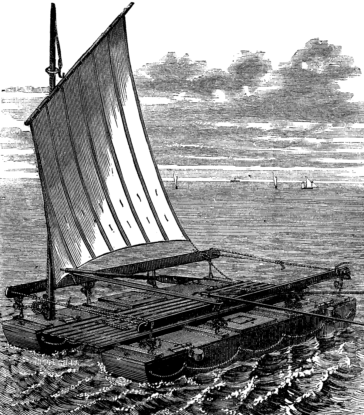
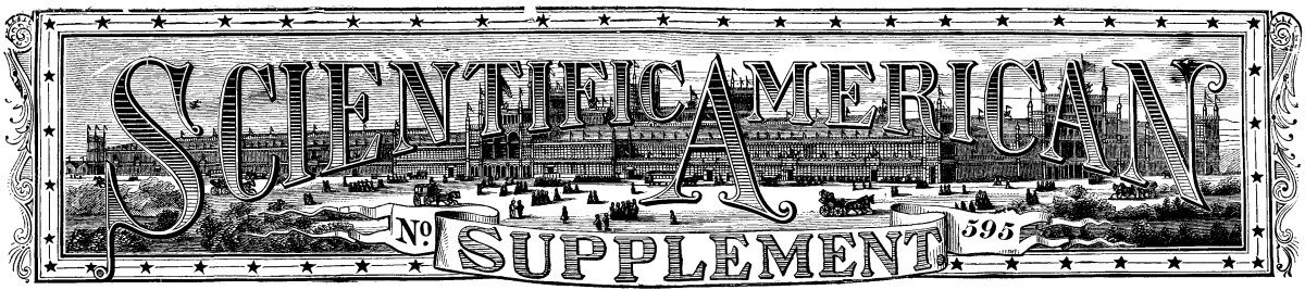
FIG. 1.—COPEMAN & PINHEY'S LIFE RAFTS.
Messrs. Copeman & Pinhey have, for some years past, done good work in this direction, and at the recent meeting of the Institution of Naval Architects, Mr. Copeman showed several models of the latest types of their life saving apparatus, both for use on torpedo boats and passenger steamers. Our illustration (Fig. 1) represents the kind of rafts supplied to her Majesty's troop ships, while Figs. 2 and 3 show deck seats convertible into rafts, which are intended for ordinary passenger steamers. The raft shown in Fig. 1 consists of two pontoons, joined by strong cross beams, and fitted with mast, sail, and oars. When not in use, the pontoons form deck seats, covered by a wooden grating, which in our illustration forms the middle part of the raft. Each pontoon has a compartment for storing provisions, and when rigged as a raft, there is a railing to prevent persons being washed overboard.
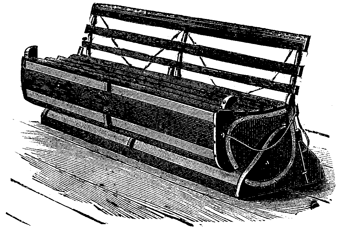
FIG. 2.

FIG. 3.
The seat life buoy, shown in Fig. 2, serves as an ordinary deck seat, being about 8 ft. long, and it consists of two portions, hinged at the back. When required for use as a life buoy, it is simply thrown forward, the seat being at the same time lifted upward, so that the top rail of the back engages with the two clips, shown at either end of the seat, and the whole structure then forms a rigid raft, as will be seen from Fig. 3. Several other appliances were shown at the Westminster Aquarium on April 13, but the two rafts we have selected for illustration will give a sufficiently correct idea of the general principles upon which the apparatus is based.—Industries.
In a recent impression we gave some particulars of the trial trip of a boat built for the Italian government by Messrs. Yarrow & Co., which attained the highest speed known, namely, as nearly as possible, 28 miles an hour. On the 14th April the sister boat made her trial trip in the Lower Hope, beating all previous performances, and attaining a mean speed of 25.101 knots, or over 28 miles an hour. The quickest run made with the tide was at the rate of 27.272 knots, or 31.44 miles per hour, past the shore. This is a wonderful performance.
In the following table we give the precise results:
| Boiler. | Receiver. | Vacuum. | Revs. | Speed. | Means. | Second Means. | |
| lb. | lb. | in. | per min. | Knots per hr. | Knots per hr. | Knots per hr. | |
| 1 | 130 | 32 | 28 | 373 | 22.641 | 24.956 | |
| 2 | 130 | 32 | 28 | 372.7 | 27.272 | 25.028 | 24.992 |
| 3 | 130 | 32 | 28 | 372 | 22.784 | 25.028 | 25.028 |
| 4 | 130 | 32 | 28 | 377 | 27.272 | 25.248 | 25.138 |
| 5 | 130 | 32 | 28 | 375 | 23.225 | 25.248 | 25.248 |
| 6 | 130 | 32 | 28 | 377 | 27.272 | ||
| Means | 130 | 32 | 28 | 374.5 | 25.101 |
The boat is 140 ft. long, and fitted with twin screws driven by compound engines, one pair to each propeller. These engines are of the usual type, constructed by Messrs. Yarrow. Each has two cylinders with cranks at 90°. The framing, and, indeed, every portion not of phosphor-bronze or gun metal, is of steel, extraordinary precautions being taken to secure lightness. Thus the connecting rods have holes drilled through them from end to end. The low pressure cylinders are fitted with slide valves. The high pressure valves are of the piston type, all being worked by the ordinary link motion and eccentrics. The engine room is not far from the mid length of the boat, and one boiler is placed ahead and the other astern of it. Each boiler is so arranged that it will supply either engine or both at pleasure. The boat has therefore two funnels, one forward and the other aft, and air is supplied to the furnaces by two fans, one fixed on the forward and the other on the aft bulkhead of the engine room.
The fan engines have cylinders 5½ in. diameter and 3½ in. stroke, and make about 1,100 revolutions per minute when at full speed, causing a plenum in the stokeholes of about 6 in. water pressure. Double steam steering gear is fitted, for the forward and aft rudder respectively, and safety from foundering is provided to an unusual degree by the subdivision of the hull into numerous compartments, each of which is fitted with a huge ejector, capable of throwing overboard a great body of water. A body of water equal to the whole displacement of the boat can be discharged in less than seven minutes. There is also a centrifugal pump provided, which can draw from any compartment. The circulating pump is not available, because it has virtually no existence, a very small pump on the same shaft as the centrifugal being used merely to drain the condensers. These last are of copper, cylindrical, and fitted with pipes through which a tremendous current of water is set up by the passage of the boat through the sea. Thus the space and weight due to a circulating pump is saved and complication avoided. The air and feed pumps are combined in one casting let into the engine room floor, quite out of the way, and worked by a crank pin in a small disk on the forward end of the propeller shaft. This is an admirable arrangement, and works to perfection.
The armament of the boat consists of two torpedo tubes in her bows, and a second pair set at a small angle to each—Yarrow's patent—carried aft on a turntable for broadside firing. There are also two quick firing 3 lb. guns on her deck. The conning tower forward is rifle proof, and beneath it and further forward is fixed the steering engine, and a compressing engine, by which air is compressed for starting the torpedoes overboard and for charging their reservoirs. A small dynamo and engine are also provided for working a search light, if necessary. The accommodation provided for the officers and crew is far in advance of anything hitherto found on board a torpedo boat.
The weather on the morning of Thursday, April 14, was anything rather than that which would be selected for a trial, or indeed any, trip on the Thames. At 11 A.M., the hour at which the boat was to leave Messrs. Yarrow's yard, Isle of Dogs, the wind was blowing in heavy squalls from the northeast, accompanied by showers of snow and hail. The Italian government was represented by Count Gandiani and several officers and engineers. In all there were about thirty-three persons on board. The displacement of the vessel was as nearly as might be 97 tons. A start was made down the river at 11:15 A.M., the engines making about 180 revolutions per minute, and the boat running at some 11½ or 12 knots.
During this time the stokehole hatches were open, but the fans were kept running at slow speed to maintain a moderate draught. The fuel used throughout the trip was briquettes made of the best Welsh anthracite worked up with a little tar. The briquettes were broken up to convenient sizes before being put in the bunkers. This fuel is not of so high evaporative efficiency as Nixon's navigation coal, but it is more suitable for torpedo boat work, because it gives out Very little dust, while the coal in closed stokeholes half smothers the firemen. Watering only partially mitigates the evil. Besides this, the patent fuel does not clinker the tube ends—a matter of vital importance.
During the run down to Gravesend, the small quantity of smoke given out was borne down and away from the tops of the funnels by the fierce head wind, and now and then a heavy spray broke on the bows, wetting everything forward. In the engine room preparations were made for taking indicator diagrams. No attempt was made to drive the boat fast, because high speeds are prohibited by the river authorities on account of the heavy swell set up.
The measured mile on the Lower Hope is on the southern bank of the river, about three miles below Gravesend. Just as the boat passed the town, in the midst of a heavy rain squall, the stokehole hatches in the deck were shut, and the dull humming roar of the fans showed that the fires were being got up. The smoke no longer rose leisurely from the funnels. It came up now with a rush and violence which showed the powerful agency at work below. A rapid vibrating motion beneath the feet was the first evidence that the engines were away full speed. As the boat gathered way she seemed to settle down to her work, and the vibration almost ceased. The measured mile was soon reached, and then in the teeth of the northeaster she tore through the water. The tide and wind were both against her. Had the tide and wind been opposed, there would have been a heavy sea on. As it was, there was quite enough; the water, breaking on her port bow, came on board in sheets, sparkling in the sun, which, the rain squall having passed, shone out for the moment. As the wind was blowing at least thirty miles an hour, and the boat was going at some twenty-six miles an hour against it, the result was a moderate hurricane on board. It was next to impossible to stand up against the fury of the blast without holding on. The mile was traversed in less than 2½ minutes, however; but the boat had to continue her course down the river for nearly another mile to avoid some barges which lay in the way, and prevented her from turning. Then the helm was put over, and she came round. There was no slacking of the engines, and astern of her the water leaped from her rudder in a great upheaved, foaming mass, some 7 ft. or 8 ft. high. Brought round, she once more lay her course. This time the wind was on her starboard quarter, or still more nearly aft. The boat went literally as fast as the wind, and on deck it was nearly calm. The light smoke from the funnels, no longer beaten down by wind, leaped up high into the air. Looking over the side, it was difficult to imagine that the boat was passing through water at all. The enormous velocity gave the surface of the river the appearance of a sheet of steel for 1 ft. or more outside the boat. Standing right aft, the sight was yet more remarkable. Although two 6 ft. screws were revolving at nearly 400 revolutions per minute almost under foot, not a bubble of air came up to break the surface. There was no wave in her wake; about 70 ft. behind her rose a gentle swelling hill.
Her wake was a broad smooth brown path, cut right through the rough surface of the river. On each side of this path rose and broke the angry little seas lashed up by the scourging wind. Along the very center of the brown track ran a thin ridge of sparkling foam, some 2 ft. high and some 20 ft. long, caused by the rudder being dragged through the water. There was scarcely any vibration. The noise was not excessive. A rapid whirr due to the engines, and a rythmical clatter due to the relief valve on one of the port engine cylinders not being screwed down hard enough, and therefore lifting a little in its seat at each stroke, made the most of it. The most prominent noise perhaps was the hum of the fans. Standing forward, the deck seems to slope away downward aft, as indeed it does, for it is to be noted that at these high speeds the forefoot of the boat is always thrown up clean out of the water—and the whole aspect of the boat: the funnels vomiting thin brown smoke, and occasionally, when a fire door is opened, a lurid pillar of flame for a moment; the whirr in the engine room; the dull thunder of the fans, produce an impression on the mind not easily expressed, and due in some measure no doubt to the exhilaration caused by the rapid motion through the air.
The best way to convey what we mean is to say that the whole craft seems to be alive, and a perfect demon of energy and strength. Many persons hold that a torpedo boat is likely to be more useful in terrifying an enemy than in doing him real harm, and we can safely say that the captain of an ironclad who saw half a dozen of these vessels bearing down on him, and did not wish himself well out of a scrape, has more nerve than most men.
The second mile was run in far less time than that in which what we have written concerning it can be read, and then the boat turned again, and once more the head wind with all its discomforts was encountered. Events repeated themselves, and so at last the sixth trip was completed, and the boat proceeded at a leisurely pace back again to Poplar. Mr. Crohn, representing Messrs. Yarrow on board, and all concerned, might well feel satisfied. We had traveled at a greater speed than had ever before been reached by anything that floats, and there was no hitch or impediment or trouble of any kind.
The Italian government may be congratulated on possessing the two fastest and most powerful torpedo boats in the world. We believe, however, that Messrs. Yarrow are quite confident that, with twin screw triple expansion engines, they can attain a speed of 26 knots an hour, and we have no reason to doubt this.—The Engineer.
The construction of dams, in some form or other, may probably rank among the very earliest of engineering works. Works of this character are not infrequently referred to in the accounts of the earliest historians; but it is to be feared that they are not always perfectly trustworthy. The subscribers to the Mudie of the period had to be considered, and their taste for the marvelous was probably not much inferior to that of our own day. When, therefore, Herodotus describes the reservoir of Moeris as formed for the control of the river floods of Nile-nourished Egypt, and of another constructed by Nebuchadnezzar at Sippara, of 140 miles in circumference, we must make allowances. But there is no question as to the existence in the East at the present day, and especially in India and Ceylon, of the remains of what may correctly be termed stupendous works; and the date of the construction of which, as regards India, is in many cases prehistoric. In Spain also the Moors, whose occupation of the peninsula terminated in the thirteenth century, have left reservoir dams of great magnitude, situated mostly in the south-eastern provinces of Murcia and Alicante, and many of which are still serviceable.
In India and Ceylon the greater number of the ancient dams or bunds are now in ruins, and this can occasion but little surprise, considering the meteorological condition of these countries. In Ceylon, for instance, the whole rainfall of the year occurs within a period of six to eight weeks, and often amounts to as much as 12 in. in the twenty-four hours, and has been known, comparatively recently, to reach nearly 19 in., the latter an amount only 2 in. or 3 in. less than the average rainfall of Lincolnshire for the whole year. In London it is only 25 in. and in the wettest district in Great Britain, viz., Cumberland, averages not more than 70 in. per annum.
The rainfall in Bombay is from 80 in. to 100 in. per annum, and throughout India may be taken as from 50 in. to 130 in., varying, as is the general rule, in direct ratio with the altitude, and limited to a few weeks in the year. Notwithstanding this, there still exist in the Madras Presidency a not inconsiderable number of ancient bunds which serve their intended purpose at the present day as well as ever. Slight mistakes did occasionally occur, as they ever will till no more dams are wanted, as is proved by the remains of some works in Ceylon, where the failure was evidently due to error, possibly due to the instruments being out of adjustment, as their base is at a higher level than the bed of the stream at the point where water from the latter was to be diverted to afford the supply.
Among the most remarkable of these ancient works is the Horra-Bera tank, the bund of which is between three and four miles in length and from 50 to 70 ft. in height, and although now in ruins would formerly impound a reservoir lake of from eight to ten miles long and three to four miles broad. There is also the Kala-Weva tank, with a bund of twelve miles in length, which would, if perfect, create a lake of forty miles in circumference. Both of these ruined works are situated in Ceylon. The third embankment of a similar character is that of the Cummum tank, situated in the Madras Presidency, and which, though ranking among the earliest works of Hindoo history, is still in such a condition as to fulfill its original intention. The area of the reservoir is about fifteen square miles, the dam about 102 ft. high, with a breadth at the crest of 76 ft., and of the section shown in the diagram.
The by-wash is cut in the solid rock altogether clear of the dam; the outlet culverts, however, are carried under the bank. We will now consider generally the methods employed in determining the site, dimensions, and methods of construction of reservoir dams adapted to the varying circumstances and requirements of modern times, with a few references to some of the more important works constructed or in progress, which it will be endeavored to make as concise and burdened with as few enumerations of dimensions as possible.
The amount of the supply of water required, and the purposes to which it is to be applied, whether for household, manufacturing, or irrigation uses, are among the first considerations affecting the choice of the site of the reservoir, and is governed by the amount of rainfall available, after deducting for evaporation and absorption, and the nature of the surface soil and vegetation. The next important point is to determine the position of the dam, having regard to the suitability of the ground for affording a good foundation and the impoundment of the requisite body of water with the least outlay on embankment works.
It has been suggested that the floods of the valley of the Thames might be controlled by a system of storage reservoirs, and notice was especially drawn to this in consequence of the heavy floods of the winter of 1875. From evidence given before the Royal Commission on Water Supply, previous to that date it was stated that a rainfall of 1 in. over the Thames basin above Kingston would give, omitting evaporation and absorption, a volume of 53,375,000,000 gallons. To prevent floods, a rainfall of at least 3 in. would have to be provided against, which would mean the construction of reservoirs of a storage capacity of say 160,000,000,000 gallons. Mr. Bailey Denton, in his evidence before that commission, estimated that reservoirs to store less than one tenth that quantity would cost £1,360,000, and therefore a 3 in. storage as above would require an outlay of, say, £15,000,000 sterling; and it will be seen that 3 in. is by no means too great a rainfall to allow for, as in July of 1875, according to Mr. Symons, at Cirencester, 3.11 in. fell within twenty-four hours. Supposing serious attention were to be given to such a scheme, there would, without doubt, be very great difficulty in finding suitable situations, from an engineering and land owner's point of view, for the requisite dams and reservoir areas.
In Great Britain and many European countries rain gauges have been established at a greater or less number of stations for many years past, and data thereby afforded for estimating approximately the rainfall of any given district or catchment basin. The term "watershed" is one which it appears to me is frequently misapplied; as I understand it, watershed is equivalent to what in America is termed the "divide," and means the boundary of the catchment area or basin of any given stream, although I believe it is frequently made use of as meaning the catchment area itself. When saying that the rain gauges already established in most of the older civilized countries afford data for an approximate estimate only, it is meant that an increase in the number of points at which observations are made is necessary, previous to the design of a reservoir dam on the catchment area above, the waters of which are proposed to be impounded, and should be continuous for a series of five or six years, and these must be compared with the observations made with the old established rain gauges of the adjacent district, say for a period of twenty years previously, and modified accordingly. This is absolutely necessary before an accurate estimate of the average and maximum and minimum rainfall can be arrived at, as the rainfall of each square mile of gathering ground may vary the amount being affected by the altitude and the aspect as regards the rainy quarter.
But this information will be of but little service to the engineer without an investigation of the loss due to evaporation and absorption, varying with the season of the year and the more or less degree of saturation of the soil; the amount of absorption depending upon the character of the ground, dip of strata, etc., the hydrographic area being, as a rule, by no means equal to the topographic area of a given basin. From this cursory view of the preliminary investigations necessary can be realized what difficulties must attend the design of dams for reservoirs in newly settled or uncivilized countries, where there are no data of this nature to go on, and where if maps exist they are probably of the roughest description and uncontoured; so that before any project can be even discussed seriously special surveys have to be made, the results of which may only go to prove the unsuitability of the site under consideration as regards area, etc. The loss due to evaporation, according to Mr. Hawksley, in this country amounts to a mean of about 15 in.; this and the absorption must vary with the geological conditions, and therefore to arrive at a satisfactory conclusion regarding the amount of rainfall actually available for storage, careful gaugings have to be made of the stream affected, and these should extend over a lengthened period, and be compounded with the rainfall. A certain loss of water, in times of excessive floods, must, in designing a dam, be ever expected, and under favorable conditions may be estimated at 10 per cent. of the total amount impounded.
As regards the choice of position for the dam of a reservoir, supposing that it is intended to impound the water by throwing an obstruction across a valley, it may be premised that to impound the largest quantity of water with the minimum outlay, the most favorable conditions are present where a more or less broad valley flanked by steep hills suddenly narrows at its lower end, forming a gorge which can be obstructed by a comparatively short dam. The accompanying condition is that the nature of the soil, i.e., the character, strata, and lie of the rock, clay, etc., as the case may be, is favorable to assuring a good foundation. In Great Britain, as a rule, dams for reservoirs have been constructed of earthwork with a puddle core, deemed by the majority of English engineers as more suitable for this purpose than masonry.
Earthwork, in some instances combined with masonry, was also a form usual in the ancient works of the East, already referred to; but it would appear from the experience of recent years that masonry dams are likely to become as common as those of earthwork, especially in districts favorable to the construction of the former, where the natural ground is of a rocky character, and good stone easily obtained.
As to the stability of structures of masonry for this purpose, as compared with earthwork, experience would seem to leave the question an open one. Either method is liable to failure, and there certainly are as many cases on record of the destruction of masonry dams as there are of those constructed of earthwork, as instanced in Algeria within the past few years. As regards masonry dams, the question of success does not seem so much to depend upon their design, as far as the mere determination of the suitable profile or cross section is concerned, as that has been very exhaustively investigated, and fairly agreed upon, from a mathematical point of view, but to be principally due to the correctness of the estimate of the floods to be dealt with, and a sufficient provision of by-wash allowed for the most extreme cases; and, lastly, perhaps the most important of all, the securing a thoroughly good foundation, and a careful execution of the work throughout.
These remarks equally apply to earthwork dams, as regards sufficient provision of by-wash, careful execution of work, and security of foundation, but their area of cross section, supposing them to be water-tight, on account of the flatness of their slopes and consequent breadth of base, is, of course, far in excess of that merely required for stability; but in these latter, the method adopted for the water supply discharge is of the very greatest importance, and will be again referred to.
Before commencing the excavation for the foundations of a dam, it is most essential that the character of the soil or rock should be examined carefully, by sinking a succession of small shafts, not mere borings, along the site, so that the depth to which the trench will have to be carried, and the amount of ground water likely to be encountered, can be reliably ascertained, as this portion of the work cannot be otherwise estimated, and as it may bear a very large proportion of the total expense of construction, and in certain cases may demonstrate that the site is altogether unsuitable for the proposed purpose.
The depth to which puddle trenches have been carried, for the purpose of penetrating water-bearing strata, and reaching impenetrable ground, in some cases, has been as much as 160 ft. below the natural surface of the ground, and the expense of timbering, pumping, and excavation in such an instance can be easily imagined. This may be realized by referring to Fig. 4, giving a cross-section of the Yarrow dam, in which the bottom of the trench is there only 85 ft. below the ground surface. In the Dale Dyke dam, Fig. 2, the bottom of the trench was about 50 ft. below the ground surface.
There is one other point which should be mentioned in connection with the form of the base of the puddle trench—that instead of cutting the bottom of the trench at the sides of the valley in steps, it should be merely sloped, so that the puddle, in setting, tends to slide down each inclined plane toward the bottom of valley, thereby becoming further compressed; whereas, should the natural ground be cut in steps, the puddle in setting tends to bulge at the side of each riser, as it may be termed, and so cause fissures. It will be noticed that the slopes of these earthwork dams vary from 7 to 1 to 2 to 1.
The depths to which some puddle trenches are carried has been objected to by some engineers, and among them Sir Robert Rawlinson, as excessive and unnecessary, and, in the opinion of the latter, the same end might be obtained by going down to a depth say of 30 ft. only, and putting in a thick bed of concrete, and also carrying up the concrete at the back of the puddle trench, with a well for collecting water, and a pipe leading the same off through the back of the dam to the down stream side. An arrangement of this kind is shown in the Yarrow dam, Fig. 4.
The thickness of the puddle wall varies considerably in the different examples given in the diagrams before you, a fair average being the Row bank of the Paisley Water Works, Fig. 6; and although in instances of dams made early in the century, such as the Glencorse dam—Fig. 5—of the Edinburgh Water Works, the puddle was of very considerable thickness, and it would appear rightly so. This practice does not seem to have been followed in many cases, as, for instance, again referring to the Dale Dyke dam, Fig. 2, where the thickness of the top was only 4 ft., with a batter of 1 in 16 downward, giving a thickness of 16 ft. at the base. For a dam 95 ft. in height this is very light, compared with that of the Vehui dam at Bombay, of which the engineer was Mr. Conybeare—Fig. 7—where the puddle wall is 10 ft. wide at the top, with a batter downward of 1 in 8, the Bann reservoir—Fig. 8—of Mr. Bateman's design, where the puddle is 8 ft. broad at the top, and other instances. The same dimension was adopted for the puddle wall of the Harelaw reservoir, at Paisley, by Mr. Alexander Leslie, an engineer of considerable experience in dam construction.
There appears to be a question as to what the composition of puddle should be, some advocating a considerable admixture of gravel with clay. There is no doubt that clay intended for puddle should be exposed to the weather for as long previous to use as possible, and subject to the action of the air at any rate, of sunshine if there be any, or of frost. When deposited in the trench, it should be spread in layers of not more than 6 in. in thickness, cut transversely in both directions, thoroughly watered, and worked by stamping.
The position of the puddle wall is, as a rule, in the center of the bank and vertical; but laying a thickness of puddle upon the inner or up stream slope, say 3 ft. thick, protected by a layer of gravel and pitching, has been advocated as preventing any portion of the dam from becoming saturated. There are, however, evident objections to this method, as the puddle being comparatively unprotected would be more liable to damage by vermin, such as water rats, etc.; and in case of the earthwork dam at the back settling, as would certainly be the case, unless its construction extended over a very lengthened period, the puddle would be almost certain to become fissured and leaky; in addition, the comparative amounts of puddle used in this manner, as compared with the vertical wall, would be so much increased. With the puddle wall in the position usually adopted, unequal settlement of the bank on either side is less liable to affect the puddle, being vertical.
It would be interesting to refer to the embankment of the Bann, or Lough Island Reavy reservoir, Fig. 8, designed by Mr. Bateman, now nearly fifty years ago, where a layer of peat was adopted both on the slope, 15 in. thick, and in front or on the up stream side of the puddle wall, 3 ft. thick. The object was, that should the puddle become fissured and leaky, the draught so created would carry with it particles of peat, which would choke up the cracks and so reduce the leakage that the alluvial matter would gradually settle over it and close it up. On the same diagram will be noticed curved lines, which are intended to delineate the way in which the earthwork of the embankment was made up. The layers were 3 ft. in thickness, laid in the curved layers as indicated.
It is a moot question whether, in making an earthwork embankment, dependence, as far as stanchness is concerned, should be placed upon the puddle wall alone or upon the embankments on either side, and especially upon the up-stream side in addition. Supposing the former idea prevails, then it can be of little moment as to how or of what material the bank on either side is made up—whether of earth or stone—placed in thin layers or tipped in banks of 3 ft. or 4 ft. high; but the opinion of the majority of engineers seems to be in favor of making the banks act not merely as buttresses to the puddle wall, and throwing the whole onus, as it may be termed, of stanchness upon that, but also sharing the responsibility and lessening the chances of rupture thereby. But to insure this, the material must be of the very best description for the purpose. Stones, if allowed at all—and in the author's opinion they should not be—should be small, few, and far between. Let those that are sifted out be thrown into the tail of the down stream slope. They will do no harm there, but the layers of earth must not approach 3 ft. in thickness nor 1 ft.—the maximum should be six in., and this applies also to the puddle. Let the soil be brought on by say one-horse carts, spread in six inch layers, and well watered. The traffic of the carts will consolidate it, and in places where carts cannot traverse it should be punned. In the Parvy reservoir dam a roller was employed for this purpose. It comprised a small lorry body holding about a yard and a half of stone, with two axles, on each of which was keyed a row of five or six wheels.
At the Oued Meurad dam, in Algeria, 95 ft. high, constructed about 23 years ago, the earthwork layers were deposited normal to the outer slope, and as the bank was carried up the water was admitted and allowed to rise to near the temporary crest, and as soon as the bank had settled, the earthwork continued another grade, and the same process repeated.
It was the practice until comparatively recently to make the discharge outlet by laying pipes in a trench under the dam, generally at the lowest point in the valley, or constructing a culvert in the same position and carrying the pipes through this, and in the earlier works the valves or sluices regulating the outflow were placed at the tail of the down stream bank, the pipes under the bank being consequently at all times subject to the pressure of the full head of the water in the reservoir. An instance of the first mentioned method is afforded by the Dale Dyke reservoir, Fig. 2, where two lines of pipes of 18 in. diameter were laid in a trench excavated in the rock and resting upon a bed of puddle 12 in. in thickness, and surrounded by puddle; the pipes were of cast iron, of the spigot and faucet type, probably yarned and leaded at the joints as usual, and the sluice valves were situated at the outer end of the pipes. As the failure of this embankment was, as we all know, productive of such terrible consequences, it may be of interest to enter a little more fully into the details of its construction. It was situated at Bradfield, six or seven miles from Sheffield, and at several hundred feet higher level. Its construction was commenced in 1858, the puddle trench was probably taken down to a depth of 40 ft. to 50 ft., a considerable amount of water being encountered. This trench was 15 ft. to 20 ft. broad at the top, and of course had to be crossed by the before mentioned line of pipes; and although the trench was filled with puddle, and the gullet cut in the rock already mentioned for carrying the pipes under the site of the dam was "padded" with a layer of 12 in. of puddle, we can imagine that the effect of the weight of the puddle wall and bank upon this line of pipes would be very different at the point where they crossed the puddle trench to what it would be where they were laid in the rock gullet and partially protected from pressure by the sides of the latter. At the trench crossing there would be a bed of puddle 50 ft. in thickness beneath the pipe, in the gullet a bed of 1 ft. in thickness. So much as regards the laying of the pipes.
The embankment had scarcely been completed when, on March 11, 1864, a storm of rain came on and nearly filled it up to the by-wash, when the bank began slowly to subside. The engineer was on the crest at the very time, and remained until the water was running over his boots; he then rushed down the other slope and was snatched out of the way as the bank burst, and the whole body of water, about 250,000,000 gallons, rushed out through the trench, carrying with it in the course of about twenty minutes 92,000 cubic yards, or say one fourth of the total mass of earthwork, causing the death of 250 human beings, not to mention cattle, and destruction of factories, dwellings, and bridges, denuding the rock of its surface soil, and, as it were, obliterating all the landmarks in its course. The greatest depth of the bank from ground level to crest was 95 ft., the top width 12 ft., and the slopes, both on the up stream and down stream sides, 2½ to 1, and the area of the reservoir 78 acres.
Mr.—now Sir Robert—Rawlinson, together with Mr. Beadmore, were called in to make a report, to lay before Parliament, upon this disaster; and having made a careful examination of the ruins, and taken evidence, they were of opinion that the mode of laying the pipes, and in such an unprotected way, was faulty, and that subsidence of the pipes probably occurred at the crossing of the puddle trench. A fissure in the puddle was created, affording a creep for the water, which, once set up, would rapidly increase the breach by scour; and this event was favored by the manner in which the bank had been constructed and the unsuitability of the material used, which, in the words of one engineer, had more the appearance of a quarry tip than of a bank intended to store water. This opinion of the cause of failure was, however, not adopted universally by engineers, the line of pipes when examined being found to be, although disjointed, fairly in line; and there having occurred a land slip in the immediate neighborhood, it was suggested that the rupture might be caused by a slip also having taken place here, especially as the substratum was of flagstone rock tilted at a considerable angle. The formation was millstone grit. This catastrophe induced an examination to be made of other storage reservoir dams in the same district, and a report on the subject was presented to Parliament by Sir Robert Rawlinson.
TYPICAL MASONRY AND EARTHWORK DAMS OF THE WORLD.
The dam of Stubden reservoir, of the Bradford water supply, also on the millstone grit, was constructed about 1859, and caused considerable anxiety for a length of time, as leakage occurred in the culvert carrying the pipes, under the embankment at a point a short distance on the down stream side of the puddle trench. This was repaired to some extent by lining with cast iron plates; and an entirely independent outlet was made by driving a curved tunnel into the hill side clear of the ends of the dam and lining it with cast iron plates. In this tunnel was then laid the main of 2 ft. diameter, and as the original culvert again became leaky, the water had to be lowered, the old masonry pulled out, and the space filled in with puddle.
The Leeming compensation reservoir of the same water supply, with a dam of 50 ft. in height, and culvert outlet, had to be treated somewhat in the same manner, as, although the reservoir had never been filled with water, in 1875, when it was examined previous to filling, it was found that the culvert was cracked in all directions; and it was deemed best to fill it up with Portland cement concrete, and drive a tunnel outlet through the hill side, as described in the case of the Stubden reservoir. The Leeshaw dam, which was being constructed at that time upon the same lines, viz., with culvert outlet under the dam, was, at the advice of Sir Robert Rawlinson, altered to a side tunnel outlet clear of the dam.
Some years previous to the failure of the Dale Dyke reservoir there occurred, in 1852, a failure of a similar character—though, as far as the author is aware, unattended by such disastrous results—at the Bilberry reservoir at Holmfirth, near Huddersfield, which had never been filled previous to the day of its failure, and arose from the dam having sunk, and being allowed to remain at a level actually below that of the by-wash; so that when the storm occurred, the dam was topped and destroyed. An after examination proved that the bank was badly constructed and the foundation imperfect.
Besides the above instances, there have been numerous failures within recent times of earthwork dams in Spain, the United States, Algeria, and elsewhere, such as that which occurred at Estrecho de Rientes, near Lorca, in Murcia, where a dam 150 ft. high, the construction of which for irrigation purposes was commenced in 1755 and completed in 1789, was filled for the first time in February, 1802, and two months later gave way, destroying part of the town of Lorca and devastating a large tract of the most fertile country, and causing the death of 600 people. The immediate cause of failure in this case the author has been unable to ascertain. In Algeria the Sig and Tlelat dams were destroyed in 1865; and in the United States of America, at Williamsburg, Hampshire Co., Massachusetts, in 1874, an earthwork dam gave way, by which 159 lives were lost and much damage done to property. In another case, viz., that of the Worcester dam, in the United States of America—impounding a volume of 663,330,000 gallons, and 41 ft. high, 50 ft. broad at the crest, and formed with a center wall of masonry, with earthwork on each side—which gave way in 1875, four years after its completion; here, as in almost all other instances of failure, the leakage commenced at a point where the pipes traverse the dam. In this case they were carried in a masonry culvert, and the leak started at about 20 ft. on the up stream side of the central wall. The opinion of Mr. McAlpine as to the cause of failure, which agrees with that of the most eminent of our own water engineers, was to the effect that "earthen dams rarely fail from any fault in the artificial earthwork, and seldom from any defect in the natural soil. The latter may leak, but not so as to endanger the dam. In nine tenths of the cases, the dam is breached along the line of the water outlet passages."
The method of forming the discharge outlet by the construction of a masonry culvert in the open has no doubt many advantages over that of tunnel driving through the hill side clear of the dam, permitting as it does of an easy inspection and control of the work as it proceeds; but a slight leakage in the instance of a side tunnel probably means nothing more than the waste of so much water, whereas in the case of the culvert traversing the site of the bank, the same amount or less imperils the stability of the bank, and in ninety-nine cases out of a hundred would, if not attended to, sooner or later be the cause of its destruction. I think the majority will therefore agree that the method of discharge outlets under the site of embankments should not be tolerated where it is possible to make an outlet in the flank of the hill, to one side, and altogether clear of the dam.
At Fig. 9 is a diagram of the Roundwood dam of the Vartry Water Works, supplying Dublin, which is a fair specimen of the class of earthwork dam with the outlet pipes carried in a culvert under the embankment, and which, perhaps, is one of the most favorable specimens of this method of construction, as the inlet valves are on the up stream of the dam, and consequently when necessary the water can be cut off from the length of pipes traversing the dam. A short description will be given. This dam is 66 ft. high at the deepest point and 28 ft. wide at the crest, having to carry a public road. The slope on the inner face is 3 to 1, and on the outer 2½ to 1. The by-wash is 6 ft. below the crest, which is about the average difference. The storage capacity of the reservoir is 2,400,000,000 gallons, or sufficient for 200 days' supply to the city. The puddle wall is 6 ft. wide at the top and 18 ft. at ground level, the bottom of the puddle trench about 40 ft. below the surface of the ground. The culvert was formed by cutting a gullet 14 ft. wide with nearly vertical sides through the rock, and covering it with a semicircular arch 4 ft. in thickness. Through this tunnel are laid a 33 in. and 48 in. main; the former for the water supply, and the latter for scouring or for emptying the reservoir on an emergency. There is a plugging of brickwork in cement under the center of the dam in the line of the puddle wall, and then stop walls built at the end of the plugging, projecting 25 ft. beyond the sides of the culvert and 8 ft. above, the space between them being filled up with cement concrete tied into the rock, and on this the puddle wall rests. This bank, like almost all others pierced by outlet pipes or culverts, was not destined to be perfect. In 1867, four years after the completion, spurts of water showed themselves in the culvert in front of the puddle wall, which began to settle, and the water had to be drawn off to admit of repairs. Diagram No. 10 shows a structure of a different character to any of these already described. This character of work is adopted on the North Poudre Irrigation Canal, in N.E. Colorado. Timber is there plentiful, and a dam of this character can be rapidly constructed, although probably not very durable, owing to liability to decay of timber. That represented is about 25 ft. high.
The author has now concluded the consideration of earthwork dams, and proposes making a few remarks upon those of masonry or concrete, with reference to some of the most important, as shown on the diagrams. Their stability, unlike those of earthwork, may be considerably increased where the contour and nature of the ground is favorable by being curved in plan, convex toward the water, and with a suitable radius. They are especially suitable for blocking narrow rocky valleys, and as such situations must, from the character of the ground, be liable to sudden and high floods, great care is necessary to make sufficient provision for overflow.
When of masonry, the stones should be bonded, not merely as they would be in an ordinary vertical wall, where the direction of the stress is perpendicular, but each course should be knit in with that above and below it in a somewhat similar manner to what is termed "random" work. And lastly, if hydraulic mortar be used, a sufficient time should elapse after construction before being subjected to strain, or in other words, before water is allowed to rise in the reservoir. For this latter reason, and also the liability to damage by sudden floods during the progress of the works, dams of Portland cement concrete, on account of their quick consolidation, possess advantages over those of hydraulic masonry apart from the necessity in the latter instance of constant supervision to prevent "scamping" by leaving chinks and spaces vacant, especially where large masses of stone or Cyclopean rubble are used.
Again, should the dam be drowned by flood during its erection, no harm would accrue were it composed of Portland cement concrete, whereas should it be of hydraulic mortar masonry, the wall would probably be destroyed or, at all events, considerably injured by the mortar being washed out of the joints. Portland cement, however, is only suitable for situations where the foundation is absolutely firm, as, should there be the slightest settlement, fissures would certainly be produced.
As regards foundations, the dam of the Puentes reservoir in Spain is somewhat remarkable—see Fig. 12. Its height is 164 ft., and the profile or cross section is of precisely the same character as that of the Alicante dam, the latter being 135 ft. in height, 65 ft. wide at the crest, and 65 ft. at the base, and erected about 300 years ago. At the Puentes dam the flanks of the valley were reliable, but, as must be frequently the case in such situations, the bed of the valley was composed to a great depth of gravel, debris, and shaky strata. The difficulty was overcome by throwing an arch, or arches, across the valley, the abutments being formed by the solid rock on each side, and building the dam upon this arching and filling in below the latter down to a sufficient depth with walling.
Bearing in mind the sudden and great floods to which dams constructed in such situations must be subjected, and, if the valley be very narrow, the probability that sufficient space at the side for a by-wash will be difficult to obtain, it would seem reasonable that in the calculation for their section allowance should be made for the possible condition of the whole length of the dam being converted into a weir, over which the waters may flow without risk of injury to the dam, to a depth of, say, at least twice that ever probable.
The topping of dams by floods is not uncommon, and if the extra strain thus induced has not been allowed for, their destruction is nearly certain, as instanced in more than one case in Algeria, where, although the average rainfall is only 15 in. yearly, a depth of 6¼ in., or more than one-third of the annual total, has been known to fall in twenty-four hours.
The Habra dam—see Fig. No. 13—completed in 1871, was destroyed by a sudden flood of this kind in December, 1881. This reservoir, with a storage capacity of 6,600,000,000 gallons, was intended for the irrigation of a cultivated bordering on the Mediterranean and the storage of floods. The height of the dam was 116.7 ft. and was provided with a by-wash of 394 ft. in length, and outlets for irrigation formed by four cast iron pipes of 31½ in. diameter through the dam. It was composed of rubble set in hydraulic mortar, the latter composed of two parts of sand to one of hydraulic lime.
For getting rid of the large deposits of sand to which all reservoirs in that country are liable, two scouring outlets were provided of the same description as those in the old Moorish dams. The profile was calculated from Delocre's formula, and was correct in this respect, supposing the by-wash to have been sufficient. But as it was otherwise, and the flood swept over the crest to the depth of about 3 ft., the enormous extra strain thus induced overthrew the dam and caused the destruction of several villages and the death of 209 persons. It must be mentioned that when the reservoir was filling, the water percolated through the masonry, giving the face wall the appearance of a huge filter, which at the time was attributed to the porous nature of the sandstone used in construction, but which more probably was due to the washing of the green mortar out of the joints.
At the Hamiz dam, also in Algeria, the water was admitted in 1884, but it showed immediately signs of weakness, so that the water had to be run out and an immense retaining wall erected to strengthen the main dam. Algeria seems to have been singularly unfortunate as regards the success of works of this description. Water was admitted to the Cheurfas reservoir in January, 1885, and it at once began to make its way through permeable ground at one end of the dam. The flushing sluice in the deepest part of the dam had become jammed, so that the pressure could not be relieved, and in February 30 ft. length of the dam was carried away, causing a flood in the river below. At some distance down stream was the Sig reservoir. The flood rushing down, topped this dam by 18 ft. and overthrew it also.
Allusion has been made to provision for scouring out sand and deposit, especially in the dams of Algeria and of Spain. The amount of sand, etc., brought down by the floods is something enormous, and the question of the best means of getting rid of it has occupied much attention. In the old Moorish reservoirs the flushing gallery, piercing the lower part of the dam, was closed by iron doors on the down stream face and blocked with timber at the upper end. When required to be flushed out, laborers passed through the gallery and broke down the timber barrier, the silt forming a wall sufficiently thick to resist the pressure of the water for the time being, and allow of the retreat of the Forlorn Hope—if the latter had luck—before giving way.
One method adopted in Algeria, which has the advantage of permitting the sediment to be utilized together with the irrigation, this sediment being very fertilizing, is to pump air down through hose extending to the bottom of the reservoir, the pumps being actuated by steam power or turbine, and the sediment thus stirred up and run off with the water through the irrigation pipes. As an example of one of the early types of masonry dams in France, reference may be made to Fig. 13, on which is shown an elevation and cross section of the Lampy dam, forming a large reservoir for feeding the Languedoc canal.
I will now refer to some of the most notable masonry dams in existence, commencing with France, where perhaps the finest is that known as the Furens, in connection with the St. Etienne Water Works, constructed between the years 1859-66, and designed by the engineers Graiff and Grandchamps. It is curved in plan, struck with a radius of 828 ft. from a center on the down stream side, and founded upon compact granite, the footings being carried down to a depth of 3 ft. 3 in. below the surface of the rock. It is of rubble masonry, in hydraulic mortar, carried up in courses of 5 ft. in depth.
The height is 170 ft. on the up stream side and 184 ft. high on the lower side, with a breadth of 9 ft. 8 in. at the crest and 110 ft. at the base, and the cross section is so designed that the pressure is nearly constant in all parts, and nowhere exceeds 93 lb. to the square inch—13,392 lb. to the square foot. The contents is equal to 52,000 cubic yards of masonry, and the cost of erection was £36,080. The capacity of the reservoir is equal to 352,000,000 gallons.
The reservoir discharges into two tunnels (see Fig. 11), driven one above the other through a hill into an adjacent valley. The lower tunnel contains three cast iron pipes, with a masonry stopping of 36 ft. long. Two of these pipes are 16 in. diameter, with regulating valves, and discharge into a well, from whence the water can be directed for the town supply or into the river. The third pipe, of 8½ in. diameter, is always open, and serves to remove any deposit in the reservoir, and to furnish a constant supply for the use of manufacturers.
The author drew attention to the difference in the section of the Furens dam, Fig. 11, as compared with that of Alicante, and of Puentes, which is similar to the latter. These two last illustrate the ancient Moorish type, and the former that of the present day. The Gileppe dam at Verviers, in Belgium, Fig. 14, although quite recently erected, viz., between the years 1869 and 1875, differs very much from the Furens type, in so far as it is of very much larger sectional area in proportion to its height, but this is accounted for by the desire of the engineer, M. Bodson, to overcome the opposition to its construction, and meet the objections and combat the fears of those whose interests—and those serious ones, no doubt—would be affected in the event of its rupture, the body of water stored being 2,701,687,000 gallons, or about eight times as much as the capacity of the Furens reservoir.
In addition to this, there was another reason, which was quite sufficient in itself to account for the extra substantiality of the dam. This reservoir is for supplying water to the cloth factories of Verviers, on the Belgian-German frontier. It is curved in plan to a radius of 1,640 ft., with a length of 771 ft., and the additional strength of the structure due to so flat a curve is probably slight.
It is built of rubble masonry, with ashlar facework, laid in hydraulic mortar. The total amount of masonry is 325,000 cubic yards. There are two weirs, at a level of 6 ft. below the crest, each 82 ft. wide. The total height, including the foundations, which are carried down from 3 ft. to 5 ft. into the rock, is 154 ft., and the breadth of the crest, which carries a road, is 49 ft. 3 in., and at the base 216 ft. The outlet pipes are carried through tunnels, which are driven on the curve into the hill side a considerable distance clear of each end of the dam.
Another very important structure is the Villar dam, Fig. 15, in connection with the water supply of Madrid, and situated on the river Lozoya. The storage capacity of this reservoir is very considerable, viz., 4,400,000,000, or nearly thirteen times as great as that of Furens. The height of the dam is 162 ft., with a breadth of 14 ft. 9 in. at the crest. It is built on the curve to a radius of 440 ft., and the length of the dam measured along the crest is 546 ft., of which 197 ft. is by-wash, thus describing nearly one-fifth of a circle, and consequently well designed to resist pressure. The dam is built of rubble masonry in hydraulic mortar, and cost £80,556.
The Stony Creek lower reservoir dam of the Geelong water supply, Fig. 16, colony of Victoria, is interesting as being constructed of concrete, in the proportion of 1 to 8½. Its erection occupied eighteen months, and cost about £18,000. It is curved in plan to a radius of 300 ft., and the greatest depth or head of water is 52 ft. 4 in. The width at the crest is only 2 ft. 8 in., although surmounted by a heavy coping of bluestone 3 ft. 3 in. broad and 1 ft. 9 in. deep. There being no facility for making a by-wash at the side, the center of the dam is dished to form a weir 30 ft. long. There are both outlet and scour pipes, and valves of 2 ft. diameter, and the capacity of the reservoir is 143,145,834 gallons.
The Paramatta dam, in New South Wales, built of masonry in hydraulic mortar, is another instance of a dam built on the curve, and which has resisted a flood of water 4 ft. in depth over the crest; and in the case of a dam of about 40 ft. high across the river Wyre, in connection with the Lancaster Water Works, made of cement concrete in proportion of 4 to 1, there has, according to Mr. Mansergh, frequently been a depth of 5 ft. of flow over it. This dam is built to a radius of 80 ft. only, and as it measures 100 ft. along the crest, must include about the fifth of a circle.
There now remain only two other examples of masonry dams, the first being that in connection with the Liverpool water supply, and known as the Vyrnwy dam, Fig. 17, this being thrown across a stream of that name in North Wales. It is now under construction, and when completed will impound an area of 1,115 acres.
The dam will be 1,255 ft. long, and formed of Cyclopean rubble set in cement mortar, and the interstices or spaces between the large masses of stone, which are rough hewn and not squared, are filled with cement concrete. The proportion of the cement mortar is 2½ to 1. These masses of stone weigh from two to eight tons each, and it is expected that the wall will be of a most solid description, as great care is being taken to fill up all spaces. The face next to the water is cemented. The area of the cross section shown on the diagram, which is at one of the deepest points, is 8,972 square feet, and the height from foundation to flood level is 129 ft., the breadth at the base being 117 ft. 9 in.
The existing dam of the New York water supply, Fig. 18, known as the Croton reservoir, is shown on the diagram. Its capacity is 364,000,000 gallons and the area 279 acres. The height is 78 ft. and width at crest 8 ft. 6 in., and is built of masonry in hydraulic mortar. The face walls are of stone laid in courses of 14 in. to 26 in., and are vertical on the up stream side, and with a batter of 1 in 2½ on the down. The hearting is of concrete for a depth of 45 ft. from the top, and the remaining depth is in Cyclopean rubble.
At Fig. 19 is shown the section of the Quaker Bridge dam, which when completed will be the largest structure of the kind in existence. It is situated on the Croton River, which is a tributary of the Hudson, about four miles below the present Croton dam. The length will be 1,300 ft. and the height 170 ft. above the river bed, or 277 ft. above the foundation. The water by-wash is 7 ft. below the crest, and the dam is 26 ft. broad at the crest and 216 ft. at the base. The capacity of the reservoir will be 32,000,000,000 gallons, or nearly a hundred times as great as that of Furens. The geological formation at the site is sienitic gneiss. The cost of the dam is estimated at £500,000.
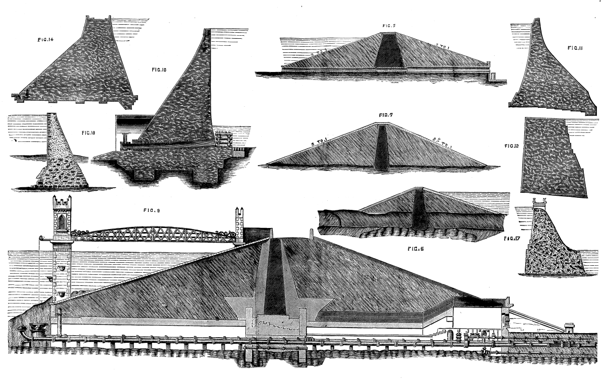
TYPICAL MASONRY AND EARTHWORK DAMS OF THE WORLD.
The accompanying table gives the pressures to which various dams are subjected, and it may be noted with regard to the weight of water, generally assumed as 62.4 lb. per cubic foot, that it will, in some districts, in time of flood, carry so much matter in suspension as to be increased to as much as 75 lb. weight, or an addition of 20 per cent., which, it may be easily imagined, will affect the conditions of stability very seriously.
| TABLE OF MAXIMUM PRESSURES. | |
| Lb. per sq. in. | |
| Gileppe (Verviers). | 88 |
| Furens (St. Etienne). | 93 |
| Puentes. | 112 |
| De Ban. | 113 |
| St. Chamond. | 114 |
| Alicante. | 154 |
| Hamiz (Algeria)—failed. | 157 |
| Habra (Algeria)—failed. | 185 |
A diagram comparing the section derived from Molesworth's formula and those of Furens, Gileppe, Vyrnwy, and Quaker Bridge, is given at Fig. 20, the limit of pressure assumed for the masonry being 93 lb. per square inch, which is that of the Furens, the Gileppe being 88.
We illustrate the new dredger Ajax, recently built for Mr. Geo. F. Smith, of Stockton, Cal.
The dredger has now been working for two weeks at Wakefield, and, we are informed, is giving entire satisfaction; having been repeatedly timed to be discharging clay at the rate of 220 cubic yards per hour.
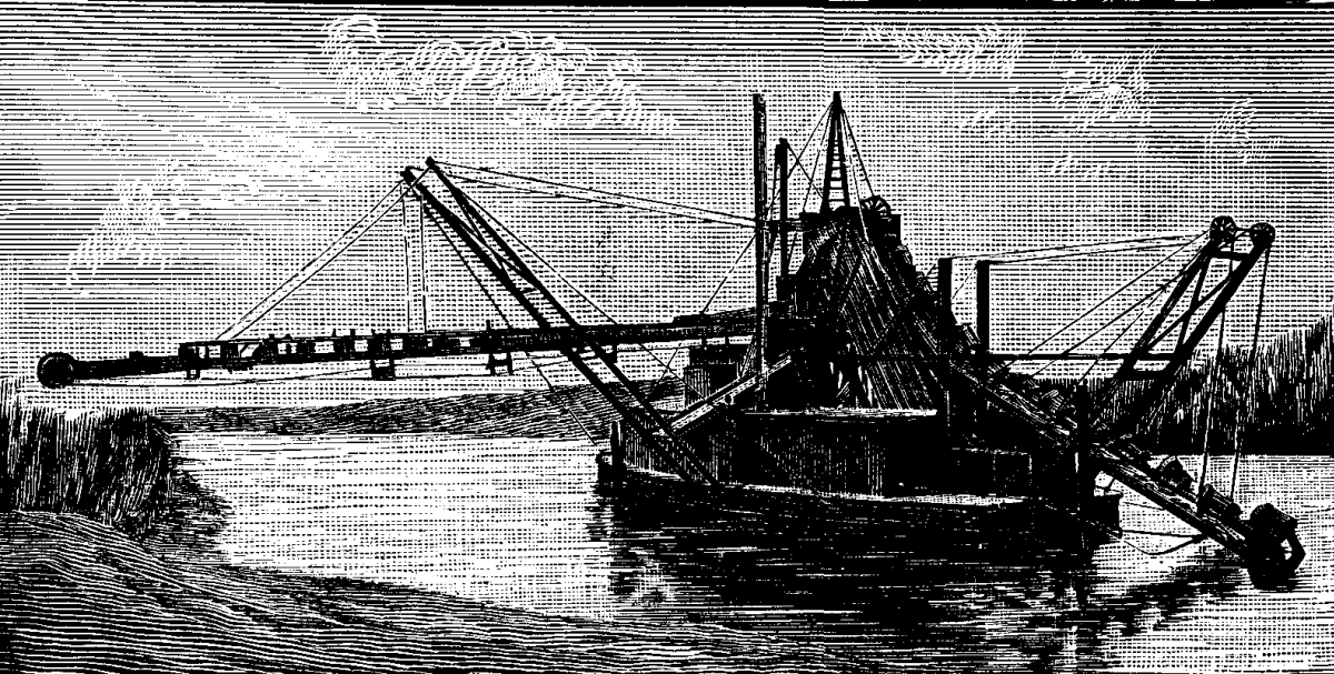
THE NEW DREDGER AJAX.
The Ajax is almost a duplicate of the last dredger designed by Mr. Ferris for levee building on Roberts Island, with such modifications and improvements as have suggested themselves in the two years it has been working.
The hull, oval in plan, is 36 ft. 10 in. by 60 ft. over all; it has four solid fore and aft bulkheads, and a well hole 5 × 12 ft. at one end for the bucket ladder.
The main engine is 10 × 24, operating, by bevel gearing and a 3½ in. vertical shaft, a 4 sided upper tumbler with 21 in. sides. This engine works also a gypsy shaft for swinging, and the conveyer that carries the mud ashore. A steam hoist with 6 × 11 engines raises and lowers the bucket ladder. The buckets, at 4 foot centers, have a struck capacity of 5 cubic feet, and are speeded to deliver from 18 to 20 a minute, according to the character of the material being handled. They are of boiler iron, with a 5 in. steel nosing. The links are of wrought iron, with cast bushings. The lower tumbler is hexagonal, on a 4 in. shaft.
The conveyer, projecting 72 ft. from the center of the boat, consists of a 5 ply rubber belt 36 in. wide; running over iron drums at each end and intermediate iron friction rollers at 3 foot centers. Ratchet and pinion on each side of conveyer ladder give means for taking up the slack of the belt and adjusting the drums to maintain them parallel.
This conveyer is the important feature of the dredge. It is entirely satisfactory in its working and delivers its material, as nearly as may be, in a dry state upon the levee. It was feared the rubber belt would be shortlived, but a 4 ply belt ran continuously for over two years on the Roberts Island dredge before it needed replacing.
The boiler is of the marine type, 52 in. by 10 ft. 6 in., with 3 in. tubes and 14 in. flues; and burns about 1,400 lb. of steam coal in a day of 12 hours. There are three pumps aboard—a hand force pump for washing boiler, a plunger pump for boiler feed, and an Evans steam pump to throw a jet of water into the delivery hopper when digging in any very tenacious material. All three are connected with the boiler.
Water tanks below deck serve to trim the boat and furnish a supply for the boiler. The dredger cuts by swinging on a center spud 16 in. in diameter, and moves forward from 8 to 10 ft. at each fleet.
The Roberts Island dredger, of which the Ajax is an improved copy, handles steadily 700 yards per day of 12 hours, in the stiffest and most tenacious clay in which it has been worked; and ranges from that average to 1,500 yards per day in soft, peaty mud.
The Ajax was built by Farrington, Hyatt & Co., of the Stockton Iron Works.
This type of dredger can be built for about $12,500, and we are informed can be relied on for a monthly average of 26,000 yards in any material met with in the overflowed lands near Stockton, delivered 50 ft. ashore, at a height of 10 or 12 ft. above the ground line.—Min. and Sci. Press.
[1]This is an ingenious proposition for utilizing a modification of the wire tramway system for overcoming obstacles (while retaining the ordinary wire tramway or any light railway on other parts of the line), made by Mr. Charles Ball, of London.
The flexible girder tramway is an improved system of constructing a modification of the well known and extensively used rope or wire tramway, and it is claimed that it will revolutionize the transport of the products of industrial operations from the place of production to the works or manufactory, railway station, shipping ports, or place of consumption; and that in the result the introduction of the flexible girder tramway will in many cases enable profits to be earned in businesses which have hitherto been unremunerative. It is declared to be at once simple, cheap, durable, and efficient. The improvement consists in the employment, in addition to the usual tram wire (a hempen rope, a wire rope, or a metallic or other rod), along which the load is transported, of a second or suspension wire or rope to which the tram wire is connected by tension rods or their equivalent at intervals between the rigid supports or piers, the object being to diminish or distribute the sagging or deflection of the tram wire, and thus lessen the steepness of the gradients over which the load has to be transported. The combined tram wire, tension rods, suspension wire, and accessories are, for convenience, designated a "flexible girder."
Another improvement consists in using, when a double line is employed, stretchers or crossheads to keep the flexible girders nearly parallel to each other, so that when necessary the load to be transported may be suspended from or borne by both tram wires jointly or simultaneously, thus permitting a load of greater weight than that for which each single tram wire is intended to be carried over the system. One indisputable claim for confidence in the flexible girder principle is said to be that, although the peculiar combination of parts constitutes a striking and valuable novelty, it contains nothing that has not been proved by the experience of years—nay, generations—to be useful, economic, and reliable. The usual practice followed in erecting suspension bridges is applicable in mounting the line, and the carriers, supports, and carriages may be of any of the usual forms. For the rapid removal of limited loads wire tramways are in universal favor, and are recognized not only as very economic and quickly constructed, but also as being in many cases the only means of transport available except by the adoption of elaborate and costly engineering works.
It has, it seems, been suggested by some who have examined the construction of the flexible girder tramway for mineral and produce traffic that it would be an additional advantage if arrangements were made for the carriage of small loads—half a dozen or so—of passengers, the primary intention being to carry the workpeople backward and forward between comparatively inaccessible mines, works, or plantations and a neighboring village or town. Compared with every other system where the line over which the load travels is elevated, the flexible girder tramway is claimed to possess many advantages—the center of gravity is kept well down, the liability of the wheels leaving the line is reduced to the minimum, the gradients are the easiest that can be obtained, there is an entire absence of jolting and extremely little vibration, and the motion is altogether smooth and regular; yet it is very questionable whether, when human life is at stake, any but an ordinary ground line should be relied upon. A living freight is far more liable than a dead freight to move during the journey; and as the safety of all overhead lines depends upon what is scientifically designated "unstable equilibrium," the flexible girder tramway is not recommendable for passenger lines, although it can, of course, be fitted for passenger traffic, a suitable vehicle and ten or a dozen good stout workmen coming well within a two-ton load, which can be readily carried.
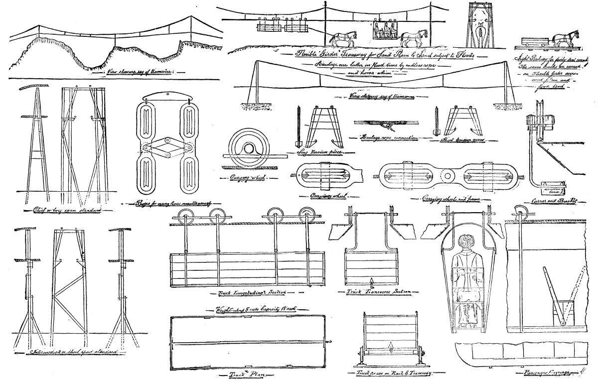
BALL'S FLEXIBLE WIRE TRAMWAY.
Rope traction or animal traction—practically speaking—is alone available for wire tramways (that is to say, if the trains are each to be propelled by its own locomotive—whether steam, springs, or electricity—the cost of construction and maintenance becomes so serious that overhead lines, however well designed, are no longer economic); and experience gained with rope traction in numerous collieries in the North of England and Lancashire districts—where it is highly appreciated—has shown that, all circumstances considered, the endless rope is preferable. The chief objection urged against wire tramways as hitherto constructed has been that the "sag" of the rope has sometimes caused annoyance to those using the property passed over, and has always added much to the cost of traction, owing to the increased power required for moving the load; this has also resulted in vastly increased wear and tear and the rapid deterioration and destruction of the wire rope. The flexible girder system so reduces the "sag" that the maximum economy and durability are obtained, and the gradients over which the load has to travel can be made as easy and regular as those upon an ordinary railway. This advantage will be the more readily appreciated when it is considered that with a given load on a gradient of 1 in 30 the resistance due to gravity alone is 200 per cent. greater than on a gradient of 1 in 150, and that the retardation and wear and tear due to friction, greater curves, and imperfections increase still more rapidly with increase of gradient, soon rendering the old sagging wire line practically worthless.
To construct an entire line of flexible girders would be not only unnecessary, but so costly as to neutralize any advantage which it may possess, yet for surmounting occasional obstacles the claim made for it—that it will sometimes permit of a line otherwise impracticable being cheaply made—seems justified. One can readily imagine a light narrow gauge line costing £1,000 per mile being laid, for example, between a mine and the shipping place, and that a swamp, river, or valley would cost more to bridge over than the whole line besides. If at this obstacle the trucks or carriages could be lifted bodily, passed along the flexible girder, and again placed on the line the other side of the obstacle, the advantage to be derived is obvious; and as the flexible girder is really little more than a suspension bridge minus the platform, and having but two suspension wires, the cost and the difficulties should both be very small.—Industrial Review.
Punkas (also called pankasor tankas) are apparatus that serve for fanning rooms throughout the entire extent of English India. These devices consist of a light wooden frame covered with canvas, from the bottom of which depends a fringe. These frames are suspended from the ceiling in such a way as to occupy nearly the entire width and length of the room. To the base of the frame is attached a cord which passes over a wheel, and which is pulled by a Hindoo domestic. After the frame has been lifted, a weight fastened to the lower part causes it to fall back again. The result of the continuous motion of this colossal fan is a coolness that is highly appreciated in a country where the temperature is at times incredibly high, and where, without the factitious breeze created by the punka, living would not be endurable. This breeze prevents perspiration, or evaporates the same as soon as it is formed. Sometimes it sinks to a light zephyr; then, if you are reading or writing, you may continue your work, but in a distracted way, with a moist brow, and with a feeling of annoyance that soon makes you leave book or pen.
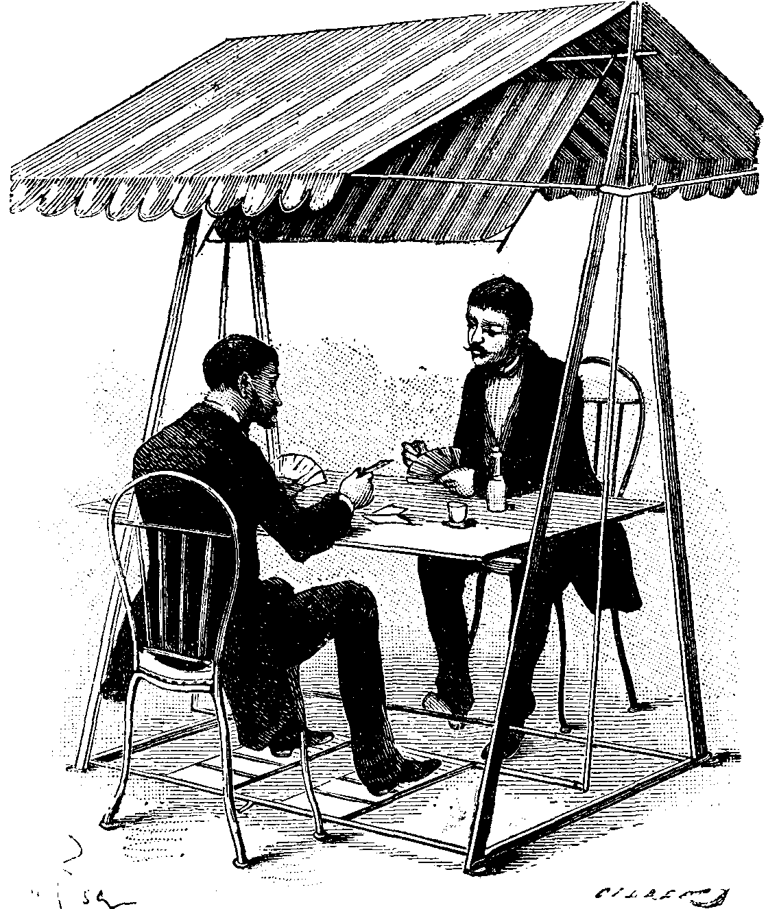
FIG. 1.—TENT OR TABLE FAN OR PUNKA.
Looking around you, you find the punka immovable. The bahi still holds the cord that pulls it, but it is because he has tied it to his hand. He has gently slid to the floor in a squatting posture. He is asleep and you are burning. A vigorous exclamation brings him to his feet all standing, and he begins to pull the punka with all his might, and you have a feeling of ease and coolness. It is like the passage from an attack of fever to a state of comfort in an intermittent disease. So the punka is seen everywhere—in the temple and court room and other public places, as well as in private dwellings. It is one of the first things to astonish the European upon his arrival in India, and it is not long before he has to bless the happy invention.
Although, in a country where the temperature generally reaches, and even often exceeds, 40° C., it is absolutely necessary to obtain by every means possible a factitious coolness without which the Indies would not be habitable for Europeans; and although there is no hesitancy in putting up these punkas everywhere to be maneuvered by bahis, the elevation of the temperature is not such in France that we are obliged to have recourse to such processes. But, without being forced thereto by nature, it is none the less true that we are often the more incommoded by heat in that we are not accustomed to it, and that in southern France, at certain hours of the day, such heat becomes absolutely unbearable. We can, it is true, obtain a little air by moving a fan, but, aside from the fact that this exercise soon becomes tiresome, it prevents the use of the hand that is fanning.
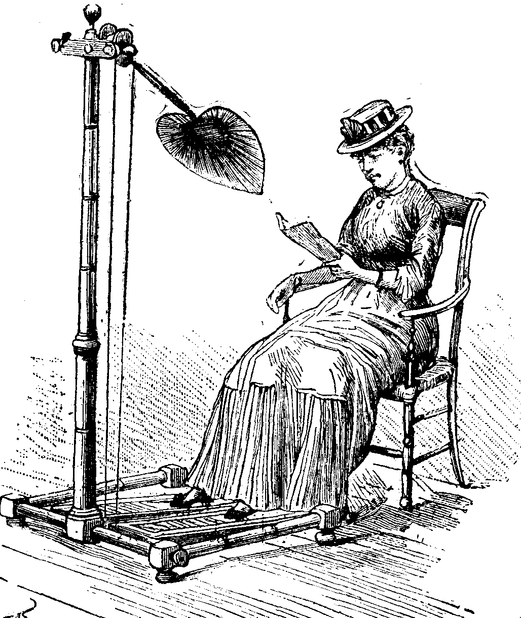
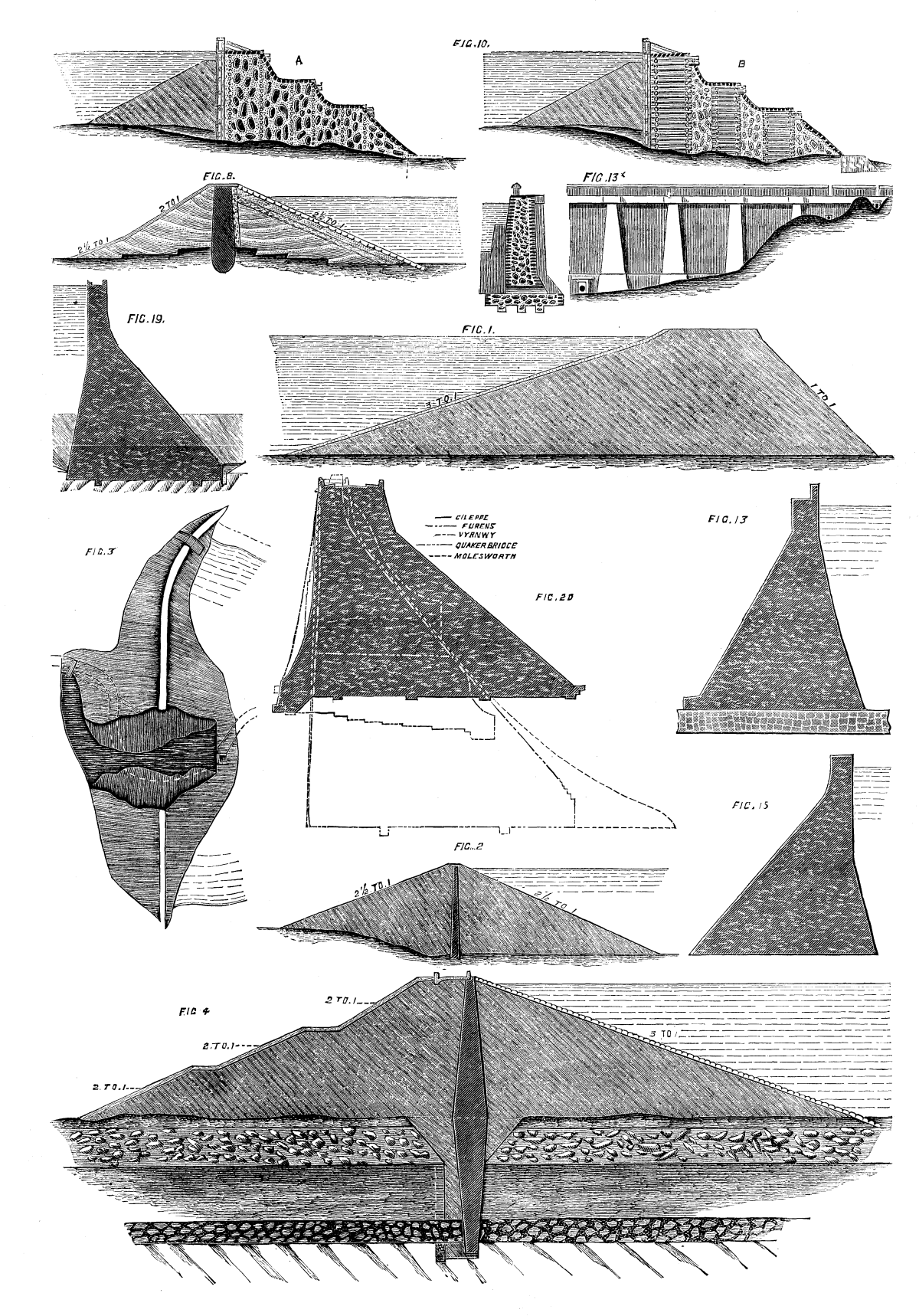
FIG 2.—AN APARTMENT FAN.
The new apparatus which have just been devised by Mr. G. Bozerian permit of one's fanning himself all day long if he wants to, without any fatigue, and while he is eating, reading, writing, etc.
In one of these apparatus, designed to be used in the open air (Fig. 1), we find a table, a tent, and a fan combined; but as each part is independent, we can have the table and fan without tent, or the fan and pedals alone without table or tent. Under the tent there is arranged a frame which pivots freely in apertures formed in the uprights that support both the tent and table. This frame is connected, through two levers, with the pedals upon which one's feet rest. The motion of the pedals is an alternating one like those of sewing machines; but while in the case of the latter a pressure has to be exerted that soon becomes very tiresome, the motion in Mr. Bozerian's apparatus is so easy that it is only necessary to raise the toes of each foot in succession in order to produce a swing of the fan through the weight alone of the foot that is pressing. The frame, which when at rest hangs perpendicularly, describes about a quarter of a circle when the extremity of the foot is raised about an inch. In consequence of the absence of passive resistances, motion occurs without any stress, and almost mechanically, giving air not only to him who is actuating the fan, but also to his vis-a-vis.
Fig. 2 represents an apartment apparatus designed to be placed in front of a table or desk, in order that one can fan himself while eating or writing. Being mounted upon casters, it can be readily moved about from one place to another. At the extremity of a wooden support, whose height may be varied at will, there is arranged a flexible fan whose handle is fixed near a pulley. A small piece of lead forms the counterpoise of the fan, which is thus completely balanced. Over the pulley runs a cord, each end of which is attached to a pedal. It will be seen that the alternate motion of these pedals must cause a rotation of the pulley in one direction or the other, and that consequently the fan will rise or fall more or less rapidly, and give a quantity of air that varies according to the rapidity with which the toes are moved.—La Nature.
The function of a punka is to cause a current of air to pass the human body so that the animal heat may escape more rapidly. This has nothing to do with ventilation; for if the punka were used in a closed room, it would still produce a cooling effect on the skin.
Let us for a moment examine into what takes place in this operation, for a clear idea of the cause of our sensations of heat is absolutely necessary to enable us to go directly to the simplest and best form of remedy. The heat we feel, and which sometimes renders us uncomfortable, is produced within us by the slow combustion of the food we eat.
This heat continues to escape from the whole surface of the body during the whole lifetime, and if anything occurs to arrest it to any great extent, the result is fatal.
In cold weather, and especially when there is much wind, the animal heat escapes very rapidly from the body, and extra clothing is used, not for any heat it imparts, but simply because it interrupts the escape of the heat, and thus maintains the temperature of the skin—that part of us which is most sensible of change of temperature. It is a wonderful fact that the heat of the interior of the body varies very little in a healthy man between India and Greenland.
The skin may bear a good many degrees of change of temperature with impunity, but the blood will only suffer a very small variation from the normal temperature of 98-4/10° Fahrenheit without serious consequences.
Well, to keep the skin at an agreeable temperature in India we generally wear a minimum of clothing, and when there is no breeze, we try to produce one with the punka.
The escape of animal heat from the body forms a subject which is much more complicated, and much more important, than the one we have met to consider, but it is impossible within the limits of our time to refer to it, except in the measure that is strictly necessary to elucidate the principles that should control the construction of the punka.
It has often been said that every engineer on his arrival in India sets about improving this useful apparatus; but if we may judge from the endless variety of forms which may be seen in shops and offices, in public and in private buildings, no general principle of construction has been recognized, and the punka, as we see it, seems to depend, for its form, more upon the taste of the workman who makes it than on anything else.
We shall begin by directing our attention to the suspended punka, which is usually hung from the ceiling, and put in movement by a cord. The object of this class of punka is to produce a downward current of air by swinging to and fro, and the best punka is the one which throws downward the greatest quantity of air with the smallest applied force.
The swinging punka is one of the simplest forms of mechanism; it can be fitted up with the most primitive materials, and however badly made, it will always have some effect. This fact has its good and its bad aspects; it brings a certain comfort within the reach of all, but it removes a great part of that necessity which, as we all know, is the mother of invention.
There are some very important natural laws which are illustrated in the punka. The first is that which governs the movement of the pendulum. The number of swings it makes per minute depends on the length of the suspending cords; a pendulum three feet long will swing 62½ times per minute, and a pendulum six feet long will swing 44¼ times per minute. Whether the swings are long ones or short ones, the number per minute is still the same. You cannot, therefore, alter the natural rate of movement of a punka unless you pull it at both sides.
The next law is that which determines that the angles of incidence and of reflection are equal. This in simple language means that it is useless to expect a good downward current of air from a slow moving and heavy punka, with long suspending cords which keep it nearly always in a vertical position to its plane of movement. Striking the air squarely as it does in its forward and backward movement, it throws almost as much air upward as downward, and of course all the air that is propelled in any other than a downward direction represents just so much power wasted.
One more law, and then we may proceed to demonstration.
As the air weighs 0.072 lb. per cubic foot at 82° Fahrenheit, and as a considerable quantity of air is put in motion, the power required to drive a punka depends upon the quantity of air it puts in motion in a given time.
The useful effect is a separate matter; it depends on the amount of air thrown in a downward direction.
To summarize; all punkas of the same size or surface, and going at the same speed, require the same amount of pulling. The best one is that which will throw down more air than any other of the same size.
To obtain the greatest result from the power expended in driving it, the punka should be placed as near as possible to the person to be cooled, as the loss of effect, due to distance, increases not in direct ratio, but in proportion to the square of the distance between punka and person. If at two feet of distance he receives one eighth of the total effect, he will at four feet of distance obtain only one thirty-second part.
In practice, the punka should just clear his head when standing, and the weighting of the curtain should be of some yielding material, so as not to damage any person who might stand in its course.
We shall now proceed to examine several forms of punka, all made to the same size, and, for purposes of comparison, we shall drive them all at the same speed. And in order that their effects may be visible to you, I have prepared an indicator which resembles more than anything else the keyboard of a piano. It consists of a series of balanced levers with blades or keys attached, forming a keyboard four feet long. The levers, each three feet long, are delicately hung on fine brass centers, and each lever is counterbalanced by a weight hung in a vessel of water, which acts as a hydraulic brake, and checks any spasmodic movement in the apparatus.
On the end of each blade is fixed a disk of white Bristol board four inches in diameter, forming a row which faces the audience.
This apparatus is so sensitive that a slight change in the humidity of the atmosphere is sufficient to throw it out of balance.
The power required to drive a punka is nearly all due to the resistance of the air; that part due to the force of gravity, and the friction of the suspending joints, is scarcely worth counting. We may readily observe the effect of the resistance of the air by swinging two pendulums of equal length and having each a large cardboard disk attached. One of the disks shall present its edge to the line of movement, and the other its face.
Exp. 1.—They are now swinging, and being both of the same gravity length, they should swing together and for an equal length of time. This they would do in a vacuum, but you have already observed that one of them is lagging, and will evidently soon come to a standstill. It is the one facing the air.
If punkas were pulled from both sides, they might be made very much lighter than they are at present, but for the sake of simplicity a single pull is preferred. They must, therefore, be made of such a weight that they will swing nearly as far on the opposite side as they are pulled on the near side; any greater weight is useless and only serves to wear out the suspending cords, which, by the way, are nearly always too numerous and too thick for their purpose.
Exp. 2.—Here is a panel punka which we shall try to use without the customary swing bar. It is of calico stretched on a light wooden frame, and you will be able to judge if it swings equally on each side of the post which supports it. The irregularity of its movement shows that it is too light, so we shall add, by way of swing bar, a bar of round iron one and a quarter inch thick.
Exp. 3.—It is now swinging regularly, and experiments have already proved that the swing bar should not be lighter than this one, which weighs four and a sixth lb. per foot of length. Iron is the best material for this purpose, as it offers the smallest surface to the resistance of the air. The length of the suspending cords is usually a matter of accident in the construction of a punka, but a little attention to the subject will soon convince us that it is one of the most important considerations.
The limit of movement of a punka is to be found in the man who pulls it. Twenty-four pulls a minute of a length of 36 inches give in practice a speed of 168 linear feet to the punka curtain. This speed is found to produce a current sufficiently rapid for practical purposes, and twenty-four pulls or beats per minute correspond to a length of suspending cord of fifty inches.
[1]The following is the method of making a kite without a tail: All the calculations necessary in order to obtain the different proportions are based upon the length of the stick, A'A, employed. Such length being found, we divide it by ten, and thus obtain what is called the unit of length. With such unit it is very easy to obtain all the proportions. The bow, K'K, consists of two pieces of osier each 5½ units in length, that form, through their union, a total length of 7 units.

KITE WITHOUT A TAIL.
After the bow has been constructed according to these measurements, it only remains to fix it to the stick in such a way that it shall be two units distant from the upper end of the stick. The balance, CC', whose accuracy contributes much to the stability of the whole in the air, consists of a string fixed at one end to the junction, D, of the bow and stick, and at the other to the stick itself at a distance of three units from the lower extremity. Next, a cord, B, is passed around the frame, and the whole is covered with thin paper.
Before raising the kite, the string, which hangs from K', is made fast at K in such a way as to cause the bow to curve backward. This curvature is increased or diminished according to the force of the wind.
Nothing remains to be done but to attach the cord to the balance, and raise the kite.—La Nature.
The accompanying drawing represents a simple but effective apparatus for drying flour and ascertaining the quantity of water contained therein. It consists of four pieces, the whole being made of block tin. A is a simple saucepan for containing the water. B is the lid, which only partially covers the top of the pan, to which it is fixed by two slots, a hole being left in the middle for the placing of the vessel which contains the flour to be operated upon, and is dropped in in the same way as the pan containing the glue is let into an ordinary glue pot. C is the spout, which serves as an outlet for the steam arising from the boiling water. D is the vessel in which the flour is placed to be experimented upon; and EE are the funnels of the lid which covers the said vessel, and which serve as escapes for the steam arising from the moisture contained in the flour.
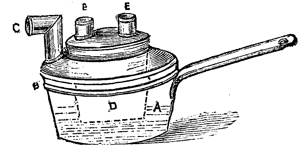
APPARATUS FOR DRYING FLOUR
Directions for use.—Partially fill the pan with water and allow it to boil. Place a given quantity of flour in the inner vessel, D, taking care first to weigh it. Subject it to the action of the boiling water until it is perfectly dry, which will be indicated by the steam ceasing to issue from the funnels. Then weigh again, and the difference in the weight will represent the quantity of moisture contained in it, dried at a temperature of 212 degrees Fahr., that of boiling water.—The Miller.
For some years past, the sale of flowers has been gradually increasing. Into the larger cities, such as Paris for example, they are introduced by the car load, and along about the first of January the consumption of them is extraordinary. All choice flowers are now being cultivated by improved methods that assure of an abundant production of them. What twenty years ago would have appeared to be an antiquated mechanism, viz., an apparatus for making bouquets, has now become a device of prime necessity by reason of the exigencies of an excessive demand.
Mr. Myard, a gardener of Chalon-sur-Saone, and vice-president of the horticultural society of that city, has devised a curious apparatus, which we represent herewith from a photograph.
This bouquet machine, which the inventor styles a bouquetiere, consists of a stationary rod (shown to the right of the figure), upon which slides a spool wound with twine, and the lower part of which is provided with three springs for keeping the twine taut. A horizontal arm at the top supports a guide or pattern whose curve is to be followed, on placing the flowers in position. This arm is removed or turned aside after the binding screw has been loosened, in order that the rod to the left that carries the bouquet may be taken out. A guide, formed of a steel ribbon, is fixed to the arm and to its movable rod by means of binding screws, which permit of its being readily elongated. This central rod can be raised or lowered at will, and, owing to these combinations, every desired form of bouquet may be obtained.
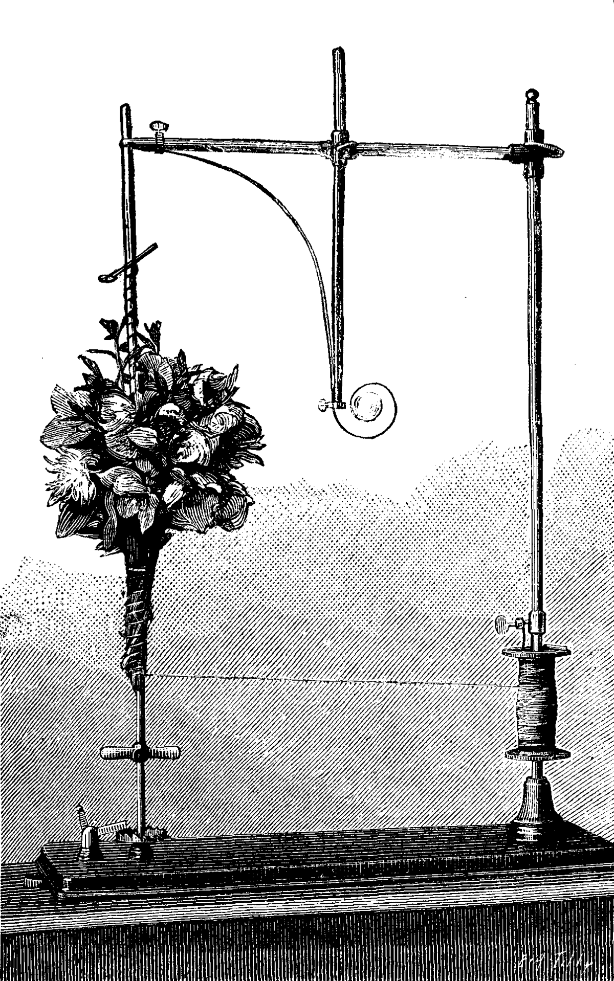
APPARATUS FOR MAKING BOUQUETS.
The rod to the left is provided with a steel pivot, and contains several apertures, into which a pin enters, thus rendering it easy to begin bouquets at different heights.
The bouquet is mounted upon the rod to the left, as shown in the figure. The pin passes through the rod and enters a loop formed at the extremity of the twine, and thus serves as a point of support, and prevents the bouquet from falling, no matter what its weight is. When the pin is removed in order that the bouquet may be taken out, the loop escapes.
At the lower part of the rod upon which the bouquet is mounted, there is a collar with three branches, by means of which a rotary motion is given to the flowers through the aid of the hand. The twine used for tying is thus wound around the stems. When the apparatus is in motion, the twine unwinds from the spool, and winds around the rod that carries the flowers, and twists about and holds every stem.
An experienced operator can work very rapidly with this little apparatus, which has been constructed with much care and ingenuity, and which enters into a series of special mechanisms that is always of interest to know about.
The manufacturer was advised to construct his apparatus so that it could be run by foot power, but, after some trials, it was found that the addition of a pedal and the mechanism that it necessitates was absolutely superfluous, the apparatus working very well such as it is.—La Nature.
[Continued from SUPPLEMENT, No. 567, page 9057.]
The motion of the connecting rod of a reciprocating steam engine is very clearly understood from the simple statement that one end travels in a circle and the other in a right line. From this statement it is also readily inferred that the path of any point between the centers of the crank and crosshead pins will be neither circular nor straight, but an elongated curve. This inference is so far correct, but the very common impression that the middle point of the rod always describes an ellipse is quite erroneous. The variation from that curve, while not conspicuous in all cases, is nevertheless quite sufficient to prevent the use of this movement for an elliptograph. To this there is, abstractly, one exception. Referring to Fig. 22 in the preceding article, it will be seen that if the crank OH and the connecting HE are of equal length, any point on the latter or on its prolongation, except E, H, and F, will describe an exact ellipse. But the proportions are here so different from anything used in steam engines (the stroke being four times the length of the crank), that this particular arrangement can hardly be considered as what is ordinarily understood by a "crank and connecting rod movement," such as is shown in Fig. 23.
The length DE of the curve traced by the point P will evidently be equal to A'B', the stroke of the engine, and that again to AB, the throw of the crank. The highest position of P will be that shown in the figure, determined by placing the crank vertically, as OC. At that instant the motions of C and C' are horizontal, and being inclined to CC' they must be equal. In other words, the motion is one of translation, and the radius of curvature at P is infinite.
To find the center of curvature at D, assume the crank pin A to have a velocity Aa. Then, since the rod is at that instant turning about the farther end A', we will have Dd for the motion of D. The instantaneous axis of the connecting rod is found by drawing perpendiculars to the directions of the simultaneous motions of its two ends, and it therefore falls at A', in the present position. But the perpendicular to the motion of the crank pin is the line of the crank itself, and consequently is revolving about O with an angular velocity represented by AOa. The motion of A' is in the direction A'B', but its velocity at the instant is zero. Hence, drawing a vertical line at A', limited by the prolongation of aO, we have A'a' for the motion of the instantaneous axis. Therefore, by drawing a'd, cutting the normal at x, we determine Dx, the radius of curvature.
Placing the crank in the opposite position OB, we find by a construction precisely similar to the above, the radius of curvature Ez at the other extremity of the axis of the curve. It will at once be seen that Ez is less than Dx, and that since the normal at P is vertical and infinite, the evolute of DPE will consist of two branches xN, zM, to which the vertical normal PL is a common asymptote. These two branches will not be similar, nor is the curve itself symmetrical with respect to PL or to any transverse line; all of which peculiarities characterize it as something quite different from the ellipse.
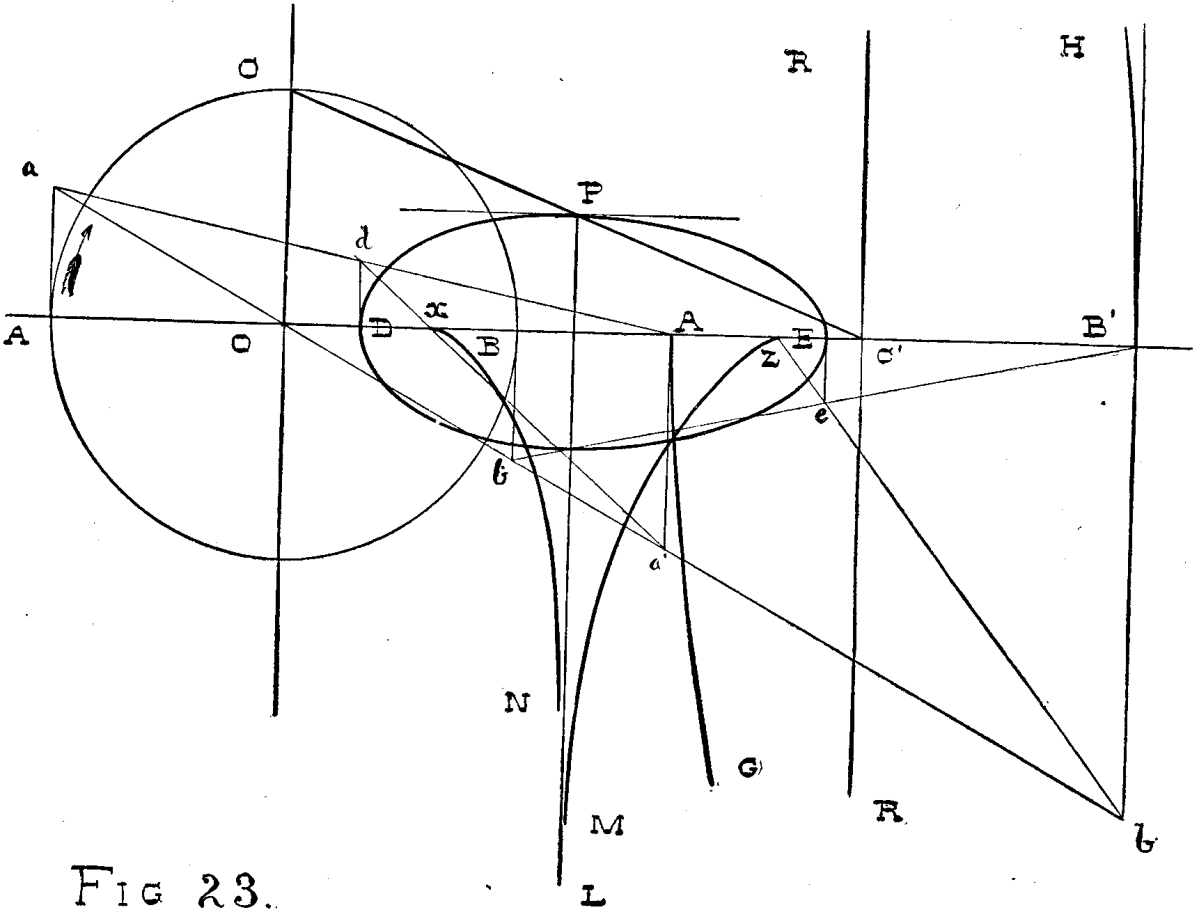
FIG. 23.
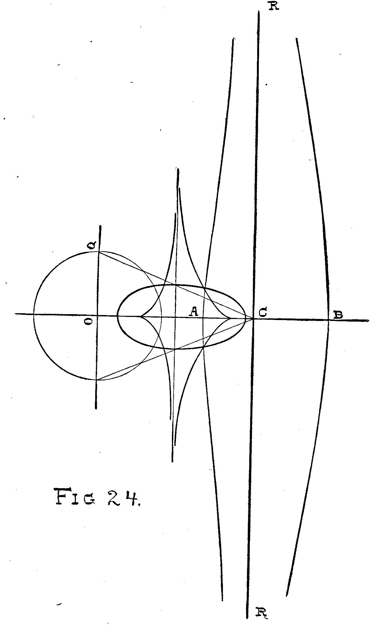
FIG. 24.
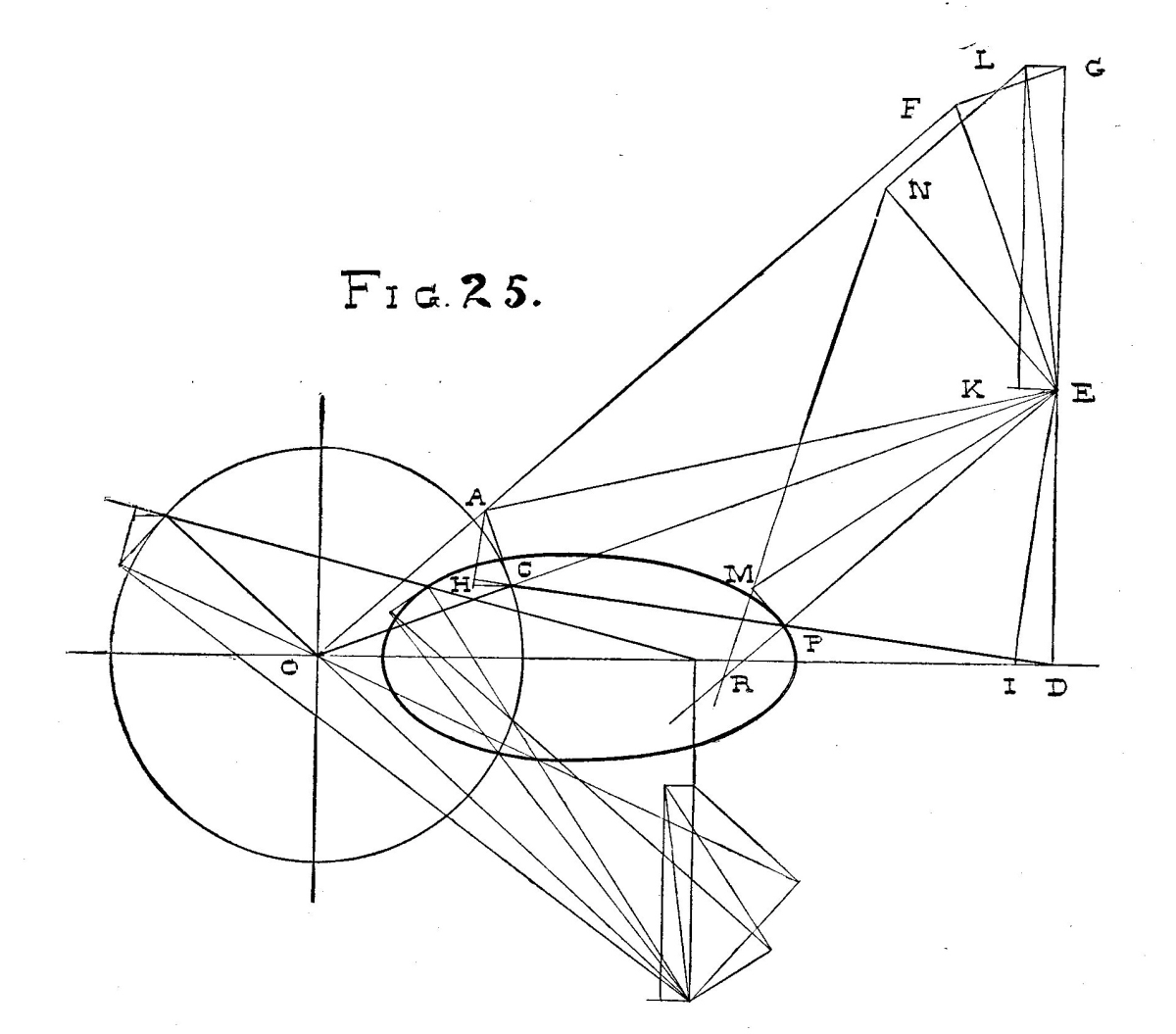
FIG. 25.
Moreover, in Fig. 22, the locus of the instantaneous axis of the trammel bar (of which the part EH corresponds to the connecting rod, when a crank OH is added to the elliptograph there discussed) was found to be a circle. But in the present case this locus is very different. Beginning at A', the instantaneous axis moves downward and to the right, as the crank travels from A in the direction of the arrow, until it becomes vertical, when the axis will be found upon C'R, at an infinite distance below AB', the locus for this quarter of the revolution being a curve A'G, to which C'R is an asymptote. After the crank pin passes C, the axis will be found above AB' and to the right of C'R, moving in a curve HB', which is the locus for the second quadrant. Since the path of P is symmetrical with respect to DE, the completion of the revolution will result in the formation of two other curves, continuous and symmetrical with those above described, the whole appearing as in Fig. 24, the vertical line through C' being a common asymptote.
In order to find the radius of curvature at any point on the generated curve, it is necessary to find not only the location of the instantaneous axis, but its motion. This is done as shown in Fig. 25. P being the given point, CD is the corresponding position of the connecting rod, OC that of the crank. Draw through D a perpendicular to OD, produce OC to cut it in E, the instantaneous axis. Assume C A perpendicular to OC, as the motion of the crank. Then the point E in OC produced will have the motion EF perpendicular to OE, of a magnitude determined by producing OA to cut this perpendicular in F. But since the intersection E of the crank produced is to be with a vertical line through the other end of the rod, the instantaneous axis has a motion which, so far as it depends upon the movement of C only, is in the direction DE. Therefore EF is a component, whose resultant EG is found by drawing FG perpendicular to EF. Now D is moving to the left with a velocity which may be determined either by drawing through A a perpendicular to CD, and through C a horizontal line to cut this perpendicular in H, or by making the angle DEI equal to the angle CEA, giving on DO the distance DI, equal to CH. Make EK = DI or CH, complete the rectangle KEGL, and its diagonal ES is, finally, the motion of the instantaneous axis.
EP is the normal, and the actual motion of P is PM, perpendicular to EP, the angle PEM being made equal to CEA. Find now the component EN of the motion ES, which is perpendicular to EP. Draw NM and produce it to cut EP produced in R the center of curvature at P.
This point evidently lies upon the branch zM of the evolute in Fig. 23. The process of finding one upon the other branch xN is shown in the lower part of the diagram, Fig. 25. The operations being exactly like those above described, will be readily traced by the reader without further explanation.
Incandescent electric lighting, already pushed to such a degree of perfection in the details of construction and installation, continually finds new exigencies that have to be satisfied. As it is more and more firmly established, it has to provide for all the comforts of existence by simple solutions of problems of the smaller class.
Take for example this case: Suppose a room, such as an office, lighted by a single lamp. The filament breaks; the room becomes dark. The bell push is not always within reach of the arm, and it is by haphazard that one has to wander around in the dark. This is certainly an unpleasant situation. The comfort we seek for in our houses is far from being provided.
M. Clerc, the well known inventor of the sun lamp, has tried to overcome troubles of this sort, and has attained a simple, elegant, and at the same time cheap solution. The cut shows the arrangement. The apparatus is connected at the points, BB', with the lighting circuit. The current entering by the terminal, B', passes through the coils of a bobbin, S, before reaching the points of attachment, a and b, of the lamp, L, the normally working one. Thence the circuit runs to B. Within the coil, S, is a small hollow cylinder, T, of thin sheet iron, which is raised parallel with the axis of the bobbin during the passage of the current through the latter. At its base the cylinder is prolonged into two little rods, h and h', which plunge into two mercury cups, G and G'. The cut shows that one of the cups, G', is connected to the terminal, B', and the other, G, to the terminal, a', of the other lamp, L'. An inspection of the cut shows just what ensues when an accident happens to the first lamp while burning. The first circuit being broken at ab, the magnetizing action of the current in the bobbin ceases, the cylinder, T, descends, and the rods, h and h', dip into the mercury. It follows that the current, always starting from the terminal, B', will by means of the cups, G and G', pass through the lamp, L', to go by the original return wire to B.
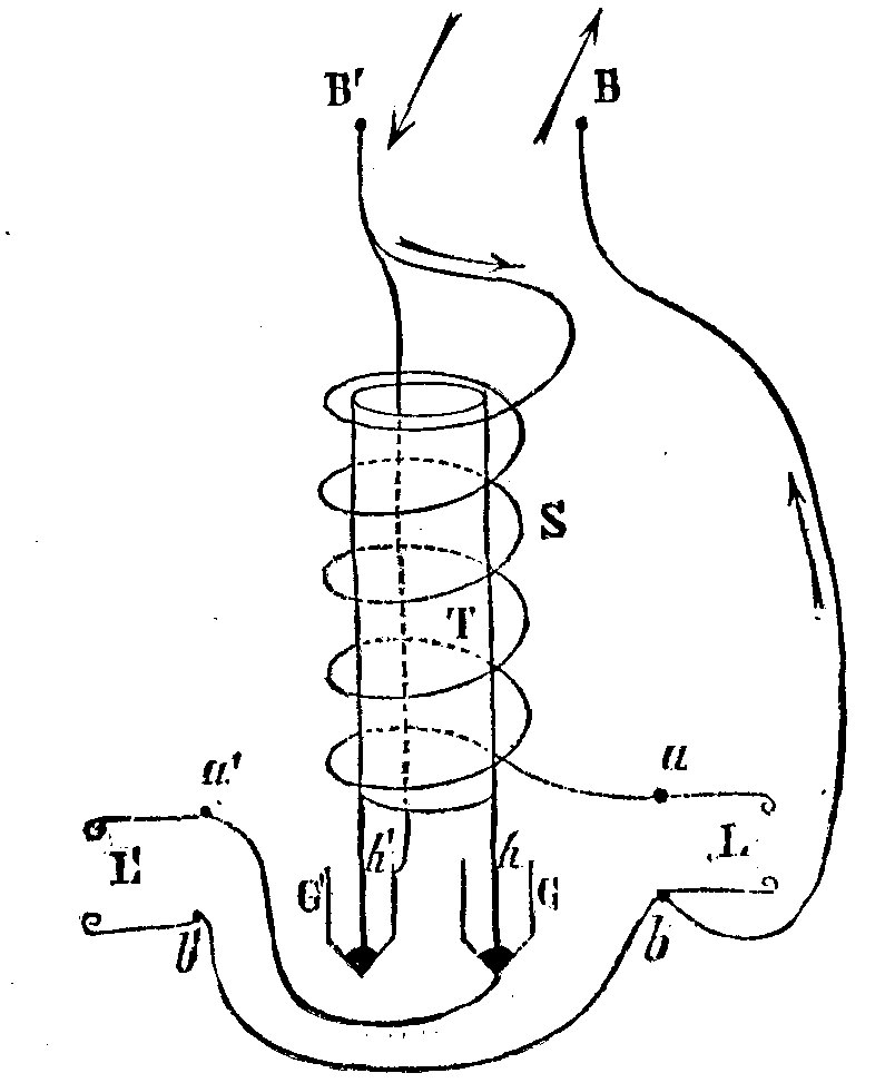
The substitution of the lamp, L, for L' is almost instantaneous. It can scarcely be perceived. It goes without saying that such an arrangement of automatic commutation is applicable to lamps with two or more filaments of which only one is to be lighted at a time. The apparatus costs little, and can be made as ornamental as desired. No exaggeration is indulged in if we pronounce it simple and ingenious. It may be used in a great variety of eases. The diameter of the wire is 55/100 (22 mm.), its length eighteen meters (60 feet), its resistance one ohm; ¾ ampere is needed to work it, and less than a watt is absorbed by it.—Electricite.
We may discourse for some time to come upon the uniformity of electric language, for universal agreement is far from being established. An important step toward the unity of this language was taken in 1881 by the congress of Paris, which rendered the use of the C.G.S. system definitive and universal. This labor was completed in 1884 by the meeting of a new congress at Paris, at which a definition of the C.G.S. and practical units was distinctly decided upon. That the unit of light defined by the congress has not rapidly come into favor is due to the fact that its practical realization is not within everybody's reach.
The work of unification should not come to a standstill on so good a road. How many times in scientific works or in practical applications do we find the same physical magnitude designated by different names, or even the use of the same expression to designate entirely different things!
The result is an increase of difficulties and confusions, not only for persons not thoroughly initiated into these notions, but also for adepts, even, in this new branch of the engineer's art. The effects of such confusion make themselves still further felt in the reading of foreign publications. Thus, for example, in Germany that part of a dynamo electric machine that is called in France the induit (armature) is sometimes styled anker, and more rarely armatur. The north pole of a freely suspended magnetized needle is the one that points toward the geographical north of the earth. In France, and by some English authors, this pole is called the south one. Among electricians of the same country, what by one is called electro-motive force is by another styled difference of potential, by a third tension, and even difference of tension.
Our confrere Ruhlmann, of the Elektrotechnische Zeitschrift, gives a still more remarkable example yet of such confusion. The word polarization, borrowed from optics, where it has an unequivocal sense, serves likewise to designate the development of the counter electro-motive force of galvanic elements, and also that essentially different condition of badly conducting substances that is brought about by the simultaneous influence of quantities of opposite electricity.
In Germany, the word induction, coupled with the word wire, for example, according to the formation of compound words in that language, may also have a double meaning, and it is by the sense alone of the phrase that we learn whether we have to do with an induced wire or an inducting one. The examples might be multiplied.
At its session of November 5, 1884, the International Society of Electricians, upon a motion of Mr. Hospitalier, who had made a communication upon this question, appointed a committee to study it and report upon it. The English Society of Electricians likewise took the subject into consideration, and one of its most active and distinguished members, Mr. Jamieson, presented the result of his labors at the May session of the society in 1885.
A discussion arose in which the committee of the International Society of Electricians was invited to take part. The committee was represented by its secretary, Mr. Hospitalier, who expressed himself in about these words: "The committee on electric notations presided over by Mr. Blauvelt has finished a part of its task, that relative to abbreviations, notations, and symbols. It will soon take up the second part, which relates to definitions and agreements." He broadly outlined the committee's ideas as follows:
In all physical magnitudes that are made use of, we have: (1) the physical magnitude itself, aside from the units that serve to measure it; (2) the C.G.S. unit that serves to measure such grandeur (granted the adoption of the C.G.S. system); (3) practical units, which, in general, have a special name for each kind of magnitude, and are a decimal multiple or sub-multiple of the C.G.S. unit, except for time and angles; (4) finally, decimal multiples and sub-multiples of these practical units, that are in current use.
The committee likewise decided always to adopt a large capital to designate the physical magnitude; a small capital to designate the C.G.S. unit, when it has a special name; a "lower case" letter for the abbreviation of each practical unit; and prefixes, always the same, for the decimal multiples and sub-multiples of the practical units.
Thus, for example, work would be indicated by the letter W (initial of the word); the C.G.S. unit is the erg, which would be written without abbreviation, on account of its being short; and the practical units would be the kilogrammeter (kgm), the grammeter (gm), etc. The multiples would be the meg-erg, the tonne-meter (t-m), etc.
Mr. Jamieson's propositions have been in great part approved. Some criticisms, however, were made during the course of the discussion, and it is for this reason that the scheme still remains open to improvements. The proposed symbols are as follows:
| A.—PRACTICAL ELECTRIC UNITS. | |
| Total resistance of a circuit. | R |
| Internal resistance of a source of current. | r1 |
| Resistance of the separate parts of a current. | r1, r2, etc. |
| Specific resistance. | ρ |
| 1 ohm. | ω |
| 1 megohm. | Ω |
| Intensity of a current. | C |
| Magnitude of 1 ampere. | A |
| 1 milliampere. | α |
| Electro-motive force. | E |
| Magnitude of 1 volt. | v |
| Capacity. | K |
| Constant of specific induction. | σ |
| 1 farad. | Φ |
| 1 microfarad. | φ |
| Quantity of electricity. | Q |
| 1 coulomb. | C |
| Electric work (volt coulomb). | vC |
| Electric effect (volt ampere, watt in one second). | W |
| Horse power. | HP |
| B.—MAGNETISM. | |
| Pole of magnet pointing toward the north. | N |
| The opposite pole. | S |
| Force of a pole, quantity of magnetism. | m |
| Distance of the poles of a magnet. | l |
| Magnetic moment. | M = m.l |
| Intensity of magnetization. | J |
| Intensity of the horizontal component of terrestrial magnetism. | H |
| C.—ELECTRIC MEASUREMENTS. | |
| Galvanometer and its resistance. | G |
| Resistance of the shunt of a galvanometer. | s |
| Battery and its internal resistance. | B |
For dynamo machines, the following designations are proposed:
| The machine itself. | D |
| Positive terminal. | +T |
| Negative terminal. | -T |
| Magnet forming the field. | FM |
| Current indicator (amperemeter). | AM |
| Tension indicator (voltameter). | MV |
| Electro-magnet. | EM |
| Luminous intensity of a lamp, in candles. | c.p. |
| Resistance of the armature. | Ra |
| Resistance of the magnet forming the field. | Rm |
| Resistance of the external circuit. | Ro |
| Intensity in the armature. | Ca |
| Intensity in the coils of the magnet. | Cm |
| Intensity in the external circuit. | Ce |
| Coefficient of self-induction. | Ls |
| Coefficient of mutual induction. | Lm |
A primary battery would be represented as in Fig. 1, and a battery of accumulators as in Fig. 2.
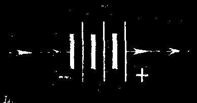
FIG. 1.

FIG. 2.
In order to designate incandescent lamps, circles would be used, and stars for arc lamps. A system of incandescent lamps arranged in multiple arc would be represented as in Fig. 3.
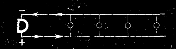
FIG. 3.
Fig. 4 and the formula
R = B + Gs/(G + s) + r
would serve for the total resistance, R, of an electric circuit, upon giving the letters the significations adopted.
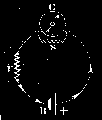
FIG. 4.
Such is, in brief, the present state of the question. The scientific bodies that have taken hold of it have not as yet furnished a fully co-ordinated work on the subject. Let us hope, however, that we shall not have to wait long. The question is of as much interest to scientific men as to practical ones.
A collection of identical symbols would have the advantage of permitting us to abridge explanations in regard to the signification of terms used in mathematical formulas. A simple examination of a formula would suffice to teach us its contents without the aid of tiresome explanatory matter.
But in order that the language shall be precise, it will be necessary for the words always to represent precise ideas that are universally accepted, and for their sense not to depend upon the manner of understanding the idea according to their arrangement in the phrase.
Nothing can be more desirable than that the societies of electricians of all countries shall continue the study of these questions with the desire of coming to a common understanding through a mutual sacrifice of certain preferences and habitudes.—E. Dieudonne, in La Lumiere Electrique.
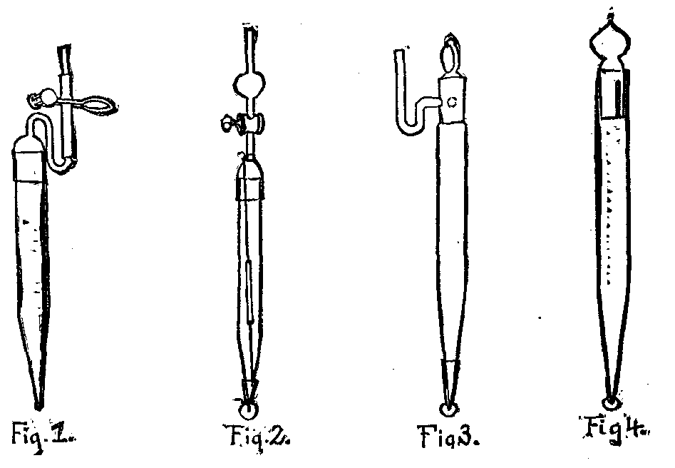
VANDERPOEL'S SETTLING TUBES.
In the February number of this Journal the writer described a new settling tube for urinary deposits which possessed several advantages over the old method with conical test-glass and pipette. For several reasons, however, the article was not illustrated, and it is for the purpose of elucidation by means of illustration, as well as to bring before the readers of the Journal two new and improved forms of the tube, that space in these columns is again sought. The first two of the figures, 1 and 2, represent the tube as originally devised; 1 denoting the tube with movable cap secured to it by means of a rubber band, and 2 the tube with a ground glass cap and stop cock. The first departure from these forms is shown at 3, and consists of a conical tube, as before, but provided with a perforated stopper, the side opening in which communicates with a side tube. The perforation in the stopper, which is easily made by a glass blower, thus allows the overflow, when the stopper is inserted into the full tube, to pass into the side tube. The stopper is then turned so as to cut off the urine in the latter from that in the large tube, and the latter is thus made tight. After allowing it to remain at rest long enough to permit subsidence of all that will settle, the stopper is gently turned and a drop taken off the lower end upon a slide, to be examined at leisure with the microscope. The cap, ground and fitted upon the lower end, is put there as a precautionary measure, as will be seen farther on.
The tube shown at 4 is, we think, an improvement upon all of the foregoing, for upon it there is no side tube to break off, and everything is comprised in a small space. As will be seen by referring to the figure, there is a slight enlargement in the ground portion of the stopper end of the tube, this protuberance coming down about one-half the length of the stopper, which is solid and ground to fit perfectly. The lower half, however, is provided with a small longitudinal slit or groove, the lower end of which communicates with the interior of the tube, while the upper end just reaches the enlargement in the side of the latter. Thus in one position of the stopper there is a communication between the tube and the outer air, while in all other positions the tube is quite shut. In all these tubes care must be taken to fill them completely with the urine, and to allow no bubbles of air to remain therein.
The first of these settling tubes was made without the ground cap on the lower end, the latter being inserted into a small test tube for safety. At the suggestion of Mr. J.L. Smith the test tube was made a part of the apparatus by fitting it (by grinding) upon the conical end, and in its present form it serves to protect the latter from dust and to prevent evaporation of the urine (or other liquid), and consequent deposition of salts, if, for any reason, the user should allow the tube to remain suspended for several days.
These tubes will be found very useful for collecting and concentrating into a small bulk the sediment contained in any liquid, whether it be composed of urinary deposits, diatoms in process of being cleaned, or any thing of like nature; and, as the parts are all of glass, the strongest acids may be used, excepting, of course, hydrofluoric acid, without harm to the tubes.—American Microscopical Journal.
[Continued from SUPPLEMENT, No. 594, page 9491.]
The information which modern methods of research have given us with regard to the floating matter in the air is of an importance which cannot be overestimated.
That the air is full of organic particles capable of life and growth is now a matter of absolute certainty. It has long been a matter of speculation, but there is a great difference between a fact and a speculation. An eminent historian has recently deprecated the distinction which is conventionally drawn between science and knowledge, but, nevertheless, such a distinction is useful, and will continue to be drawn. A man's head may be filled with various things. His inclination may lead him, for example, to study archaic myths in the various dialects which first gave them birth; he may have a fancy for committing to memory the writings of authors on astrology, or the speculations of ancient philosophers, from Aristotle and Lucretius downward. Such a one may have a just claim to be considered a man of learning, and far be it from me to despise the branches of knowledge toward which his mind has a natural bent. But in so far as his knowledge is a knowledge of fancies rather than facts, it has no claim to be called science.
Fancies, however beautiful, cannot form a solid basis for action or conduct, whereas a scientific fact does. It is all very well to suppose that such and such things may be, but mere possibilities, or even probabilities, do not breed a living faith. They often foster schism, and give rise to disunited or opposed action on the part of those who think that such and such things may not be.
When, however, a fancy or a speculation becomes a fact which is capable of demonstration, its universal acceptance is only a matter of time, and the man who neglects such facts in regulating his actions or conduct is rightly regarded as insane all the world over.
The influence of micro-organisms on disease is emerging more and more, day by day, from the regions of uncertainty, and what once were the speculations of the few are now the accepted facts of the majority.
Miquel's experiments show very clearly that the number of microbes in the air corresponds with tolerable closeness to the density of population. From the Alpine solitudes of the Bernese Oberland to the crowded ward of a Parisian hospital, we have a constantly ascending ratio of microbes in the air, from zero to 28,000 per cubic meter. Their complete absence on the Alps is mainly due to the absence of productive foci. Organic matter capable of nourishing microbes is rare, and the dryness and cold prevent any manifestation of vitality or increase. Whence come the large number of microbes in the crowded places and in hospitals?
Every individual, even in health, is a productive focus for microbes; they are found in the breath, and flourish luxuriantly in the mouth of those especially who are negligent in the use of the tooth brush. When we speak of "flourishing luxuriantly," what do we mean? Simply that these microbes, under favorable circumstances, increase by simple division, and that one becomes about 16,000,000 in twenty-four hours.
The breath, even of healthy persons, contains ammonia and organic matter which we can smell. When the moisture of the breath is condensed and collected, it will putrefy. Every drop of condensed moisture that forms on the walls of a crowded room is potentially a productive focus for microbes. Every deposit of dirt on persons, clothing, or furniture is also a productive focus, and production is fostered in close apartments by the warmth and moisture of the place. In hospitals productive foci are more numerous than in ordinary dwellings.
If microbes are present in the breath of ordinary individuals, what can we expect in the breath of those whose lungs are rotten with tubercular disease? Then we have the collections of expectorated matter and of other organic secretions, which all serve as productive foci. Every wound and sore, when antiseptic precautions are not used, becomes a most active and dangerous focus, and every patient suffering from an infective disease is probably a focus for the production of infective particles. When we consider, also, that hospital wards are occupied day and night, and continuously for weeks, it is not to be wondered at that microbes are abundant therein.
I want especially to dwell upon the fact that foci, and probably productive foci, may exist outside the body. It is highly probable, judging from the results of experiments, that every collection of putrescible matter is potentially a productive focus of microbes. The thought, of a pit or sewer filled with excremental matters mixed with water, seething and bubbling in its dark warm atmosphere, and communicating directly (with or without the intervention of that treacherous machine called a trap) with a house, is enough to make one shudder, and the long bills of mortality already chargeable to this arrangement tell us that if we shudder we do not do so without cause. As an instance of the way in which dangers may work in unsuspected ways, I may mention the fact that Emmerich, in examining the soil beneath a ward of a hospital at Amberg, discovered therein the peculiar bacillus which causes pneumonia, and which had probably been the cause of an outbreak of pneumonia that had occurred in that very ward.
The importance of "Dutch cleanliness" in our houses, and the abolition of all collections of putrescible matter in and around our houses, is abundantly evident.
It will not be without profit to examine some well-known facts, by the aids of the additional light which has been thrown upon them by the study of the microbes which are in the media around us.
There is no better known cause of a high death rate than overcrowding. Overcrowding increases the death rate from infectious diseases, especially such as whooping cough, measles, scarlet fever, diphtheria, small-pox, and typhus. The infection of all these diseases is communicable through the air, and where there is overcrowding, the chance of being infected by infective particles, given off by the breath or skin, is of course very great. Where there is overcrowding, the collections of putrescible filth are multiplied, and with them probably the productive foci of infective particles. Tubercular disease, common sore throat, chicken-pox, and mumps, are also among the diseases which are increased by overcrowding.
To come to details which are more specific, let us consider the case of some diseases which are definitely caused by floating matter in the air. First, let us take one which is apparently attributable to pollen.
Among diseases which are undoubtedly caused by floating matter in the air must be reckoned the well-known malady "hay fever," which is a veritable scourge during the summer months to a certain percentage of persons, who have, probably, a peculiarly sensitive organization to begin with, and are, in a scientific sense, "irritable."
This disease has been most thoroughly and laboriously investigated by Mr. Charles Blackley, of Manchester, who, being himself a martyr to hay fever, spent ten years in investigating the subject, and published the result in 1873, in a small work entitled "Experimental Researches on the Causes and Nature of Catarrhus æstivus (hay fever or hay asthma)."
Mr. Blackley had little difficulty in determining that the cause of his trouble was the pollen of grasses and flowers, and his investigations showed that the pollen of some plants was far more irritating than the pollen of others. The pollen of rye, for example, produced very severe symptoms of catarrh and asthma, when inhaled by the nose or mouth. Mr. Blackley came to the conclusion that the action of the pollen was partly chemical and partly mechanical, and that the full effect was not produced until the outer envelope burst and allowed of the escape of the granular contents.
Having satisfied himself that pollen was capable of producing all the symptoms of hay fever, Mr. Blackley next sought to determine, by a series of experiments, the quantity of pollen found floating in the atmosphere during the prevalence of hay fever, and its relation to the intensity of the symptoms. The amount of pollen was determined by exposing slips of glass, each having an area of a square centimeter, and coated with a sticky mixture of glycerine, water, proof spirit, and a little carbolic acid. Mr. Blackley gives two tables, showing the average number of pollen grains collected in twenty-four hours on one square of glass, between May 28 and August 21, in both a rural and an urban position. The maximum both in town and country was reached on June 28, when in the town 105 pollen grains were deposited, and in the country 880 grains. The number of grains deposited was found to vary much, falling almost to zero during heavy rain and rising to a maximum if the rain were followed by bright sunshine. Mr. Blackley found that the severity of his own symptoms closely corresponded to the number of pollen grains deposited on his glasses. Mr. Blackley devised some very ingenious experiments to determine the number of grains floating in the air at different altitudes. The experiments were conducted by means of a kite, to which the slips of glass were attached, fixed in an ingenious apparatus, by means of which the surface of the glass was kept covered until a considerable altitude had been reached. Mr. Blackley's first experiment gave as a result that 104 pollen grains were deposited in the glass attached to the kite, while only 10 were deposited on a glass near the ground. This experiment was repeated. Again and again, and always with the same result, there was more pollen in the upper strata of the air than in the lower.
A very interesting experiment was performed at Filey, in June, 1870. A breeze was blowing from the sea, and had been blowing for 12 or 15 hours. Mr. Blackley flew his kite to an elevation of 1,000 feet. The glass attached to the kite was exposed for three hours, and on it there were 80 grains of pollen, whereas a similar glass, exposed at the margin of the water, showed no pollen nor any organic form. Whence came this pollen collected on the upper glass? Probably from Holland or Denmark. Possibly from some point nearer the center of Europe.
A study of the terrible disease which so often attacks the potato crop in this country will serve, I think, to bring forcibly before you certain untoward conditions which may be called climatic, and which are attributable to fungoid spores in the air.
With the potato disease you are all, probably, more or less practically acquainted. When summer is at its height, and when the gardeners and farmers are all looking anxiously to the progress of their crops, how often have we heard the congratulatory remark of "How well and strong those potatoes look!" Such a remark is most common at the end of July or the beginning of August, when the green part, or haulm, of the plant is looking its best, and when the rows of potatoes, with their elegant rich foliage and bunches of blossom, have an appearance which would almost merit their admission to the flower border. The same evening, it may be, there comes a prolonged thunder storm, followed by a period of hot, close, moist, muggy weather. Four-and-twenty hours later, the hapless gardener notices that certain of his potato plants have dark spots upon some of their leaves. This, he knows too well, is the "plague spot," and if he examine his plants carefully, he will perhaps find that there is scarcely a plant which is not spotted. If the thunder shower which we have imagined be followed by a long period of drought, the plague may be stayed and the potatoes saved; but if the damp weather continue, the number of spotted leaves among the potatoes increases day by day, until the spotted leaves are the majority; and then the haulm dies, gets slimy, and emits a characteristic odor; and it will be found that the tubers beneath the soil are but half developed, and impregnated with the disease to an extent which destroys their value.
Now, the essential cause of the potato disease is perfectly well understood. It is parasitical, the parasite being a fungus, the Peronospora infestans, which grows at the expense of the leaves, stems, and tubers of the plant until it destroys their vitality. If a diseased potato leaf be examined with the naked eye, it will be seen that, on the upper surface, there is an irregular brownish black spot, and if the under surface of the leaf be looked at carefully, the brown spot is also visible, but it will be seen to be covered with a very faint white bloom, due to the growth of the fungus from the microscopic openings or "stomata," which exist in large numbers on the under surface of most green leaves. The microscope shows this "bloom" to be due to the protrusion of the fungus in the manner stated, and on the free ends of the minute branches are developed tiny egg shaped vessels, called "conidia," in which are developed countless "spores," each one of which is theoretically capable of infecting neighboring plants.
Now, it is right to say that, with respect to the mode of spread of the disease, scientific men are not quite agreed. All admit that it may be conveyed by contact, that one leaf may infect its neighbors, and that birds, flies, rabbits, and other ground game may carry the disease from one plant to another and from one crop to another. This is insufficient to account for the sudden onset and the wide extent of potato "epidemics," which usually attack whole districts at "one fell swoop." Some of those best qualified to judge believe that the spores are carried through the air, and I am myself inclined to trust in the opinion expressed by Mr. William Carruthers, F.R.S., before the select committee on the potato crop, in 1880. Mr. Carruthers' great scientific attainments, and his position as the head of the botanical department of the British Museum, and as the consulting naturalist of the Royal Agricultural Society, at least demand that his opinion should be received with the greatest respect and consideration. Mr. Carruthers said (report on the potato crop, presented to the House of Commons, July 9, 1880, question 143 et seq.): "The disease, I believe, did not exist at all in Europe before 1844.... Many diseases had been observed; many injuries to potatoes had been observed and carefully described before 1844; but this particular disease had not. It is due to a species of plant, and although that species is small, it is as easily separated from allied plants as species of flowering plants can be separated from each other. This plant was known in South America before it made its appearance in this country. It has been traced from South America to North America, and to Australia, and it made its first appearance in Europe in Belgium, in 1844, and within a very few days after it appeared in Belgium, it was noticed in the Isle of Wight, and then within almost a few hours after that it spread over the whole of the south of England and over Scotland.... When the disease begins to make its appearance, the fungus produces these large oblong bodies (conidia), and the question is how these bodies are spread, and the disease scattered.... I believe that these bodies, which are produced in immense quantities, and very speedily, within a few hours after the disease attacks the potato, are floating in the atmosphere, and are easily transplanted by the wind all over the country. I believe this is the explanation of the spread of the disease in 1844, when it made its appearance in Belgium. The spores produced in myriads were brought over in the wind, and first attacked the potato crops in the Isle of Wight, and then spread over the south of England. The course of the disease is clearly traced from the south of England toward the midland counties, and all over the island, and into Scotland and Ireland. It was a progress northward.... This plant, the Peronospora infestans, will only grow on the Solanum tuberosum, that is, the cultivated potato.... Just as plants of higher organization choose their soils, some growing in the water and some on land, so the Peronospora infestans chooses its host plant; and its soil is this species, the Solatium tuberosum. It will not grow if it falls on the leaves of the oak or the beech, or on grass, because that is not its soil, so to speak. Now, the process of growth is simply this: When the conidia fall on the leaf, they remain there perfectly innocent and harmless unless they get a supply of water to enable them to germinate.... The disease makes its appearance in the end of July or the beginning of August, when we have, generally, very hot weather. The temperature of the atmosphere is very high, and we have heavy showers of rain."
The warmth and moisture are, in fact, the conditions necessary for the germination of the conidia. Their contents (zoospores) are liberated, and quickly grow in the leaf, and soon permeate every tissue of the plant.
It was clearly established before the committee that not all potatoes were equally liable to the disease. The liability depends upon strength of constitution. It is well known that potatoes are usually, almost invariably, propagated by "sets," that is, by planting tubers, or portions of tubers, and this method of propagation is analogous to the propagation of other forms of plants by means of "cuttings." When potatoes are raised from seed, it is found that some of the "seedlings" present a strength of constitution which enables them to resist the disease for some years, even though the subsequent propagation of the seedling is entirely from "sets." The raising of seedling potatoes is a tedious process, but the patience of the grower is often rewarded by success, and I may allude to the fact that the so-called "Champion potato," raised from seed in the first instance by Mr. Nicoll, in Forfarshire, and since propagated all over the country, has enjoyed, deservedly as it would appear, a great reputation as a disease-resisting potato; but all who have a practical knowledge of potato growing seem agreed that we cannot expect its disease-resisting quality to last at most more than twenty years from its first introduction (in 1877), and that in time the constitution of the "Champion" will deteriorate, and it will become a prey to disease.
There is some evidence to show, also, that the constitution of the potato may be materially influenced by good or bad culture. Damp soils, insufficient or badly selected manures, the selection of ill developed potatoes for seed, and the overcrowding of the "sets" in the soil, all seem to act as causes which predispose the potatoes to the attacks of the parasite. Strong potatoes resist disease, just as strong children will; while weak potatoes, equally with weak children, are liable to succumb to epidemic influences.
The following account of some exact experiments carried out by Mr. George Murray, of the Botanical Department of the British Museum, seems to show that Mr. Carruthers' theory as to the diffusion of conidia through the air is something more than a speculation:
"In the middle of August, 1876," says Mr. Murray, "I instituted the following experiments, with the object of determining the mode of diffusion of the conidia of Peronospora infestans.
"The method of procedure was to expose on the lee side of a field of potatoes, of which only about two per cent, were diseased, ordinary microscopic slides, measuring two inches long by one inch broad, coated on the exposed surface with a thin layer of glycerine, to which objects alighting would adhere, and in which, if of the nature of conidia, they would be preserved. These slides were placed on the projecting stones of a dry stone wall which surrounded the field, and was at least five yards from the nearest potato plant. During the five days and nights of the experiment, a gentle wind blew, and the weather was, on the whole, dry and clear. Every morning, about nine o'clock, I placed fourteen slides on the lee side of the field, and every evening, about seven o'clock, I removed them, and placed others till the following morning at nine o'clock. The fourteen slides exposed during the day, when examined in the evening, showed (among other objects):
On the first day.              15 conidia.
     " second day.             17 "
     " third day.              27 "
     " fourth day.              4 "
     " fifth day.               9 "
"On none of the five nights did a single conidium alight on the slides. This seemed to me to prove that during the day the conidia, through the dryness of the atmosphere and the shaking of the leaves, became detatched and wafted by the air; while during the night the moisture (in the form of dew, and on one occasion of a slight and gently falling shower) prevented the drying of the conidia, and thus rendered them less easy of detachment.
"I determined the nature of the conidia (1) by comparing them with authentic conidia directly removed from diseased plants; (2) by there being attached to some of them portions of the characteristic conidiaphores; and (3) by cultivating them in a moist chamber, the result of which was, that five conidia, not having been immersed in the glycerine, retained their vitality, which they showed by bursting and producing zoospores in the manner characteristic of Peronospora infestans."
Let us look at another disease by the light of recent knowledge, viz., the epidemic influenza, concerning which I remember hearing much talk, as a child, in 1847-48. There has been no epidemic of this disease in the British Isles since 1847, but we may judge of its serious nature from the computation of Peacock that in London alone 250,000 persons were stricken down with it in the space of a few days. It is characteristic of this disease that it invades a whole city, or even a whole country, at "one fell swoop," resembling in its sudden onset and its extent the potato disease which we have been considering.
The mode of its spreading forbids us to attribute it, at least in any material degree, although it may be partially so, to contagion in the ordinary sense, i.e., contagion passing from person to person along the lines of human intercourse. It forbids us also to look at community of water supply or food, or the peculiarities of soil, for the source of the disease virus. We look, naturally, to some atmospheric condition for the explanation. That the atmosphere is the source of the virus is made more likely from the fact that the disease has broken out on board ship in a remarkable way. In 1782, there was an epidemic, and on May 2 in that year, says Sir Thomas Watson—
"Admiral Kempenfelt sailed from Spithead with a squadron, of which the Goliah was one. The crew of that vessel were attacked with influenza on May 29, and the rest were at different times affected; and so many of the men were rendered incapable of duty by this prevailing sickness, that the whole squadron was obliged to return into port about the second week in June, not having had communication with any port, but having cruised solely between Brest and the Lizard. In the beginning of the same month another large squadron sailed, all in perfect health, under Lord Howe's command, for the Dutch coast. Toward the end of the month, just at the time, therefore, when the Goliah became full of the disease, it appeared in the Rippon, the Princess Amelia, and other ships of the last mentioned fleet, although there had been no intercourse with the land."
Similar events were noticed during the epidemic of 1833:
"On April 3, 1833, the very day on which I saw the first two cases that I did see of influenza—all London being smitten with it on that and the following day—the Stag was coming up the Channel, and arrived at two o'clock off Berry Head on the coast of Devonshire, all on board being at that time well. In half an hour afterward, the breeze being easterly and blowing off the land, 40 men were down with the influenza, by six o'clock the number was increased to 60, and by two o'clock the next day to 160. On the self-same evening a regiment on duty at Portsmouth was in a perfectly healthy state, but by the next morning so many of the soldiers of the regiment were affected by the influenza that the garrison duty could not be performed by it."
After reviewing the various hypotheses which had been put forward to account for the disease, sudden thaws, fogs, particular winds, swarms of insects, electrical conditions, ozone, Sir Thomas Watson goes on to say:
"Another hypothesis, more fanciful perhaps at first sight than these, yet quite as easily accommodated to the known facts of the distemper, attributes it to the presence of innumerable minute substances, endowed with vegetable or with animal life, and developed in unusual abundance under specific states of the atmosphere in which they float, and by which they are carried hither and thither."
This hypothesis has certainly more facts in support of it now than it had when Sir Thomas Watson gave utterance to it in 1837. And when another epidemic of influenza occurs, we may look with some confidence to having the hypothesis either refuted or confirmed by those engaged in the systematic study of atmospheric bacteria. Among curious facts in connection with influenza, quoted by Watson, is the following: "During the raging of one epidemic, 300 women engaged in coal dredging at Newcastle, and wading all day in the sea, escaped the complaint." Reading this, the mind naturally turns to Dr. Blackley's glass slide exposed on the shore at Filey, and upon which no pollen was deposited, while eighty pollen grains were deposited on a glass at a higher elevation.
Let us next inquire into the evidence regarding the conveyence of small-pox through the air. In the supplement to the Tenth Report of the Local Government Board for 1880-81 (c. 3,290) is a report by Mr. W.H. Power on the influence of the Fulham, Hospital (for small-pox) on the neighborhood surrounding it. Mr. Power investigated the incidence of small-pox on the neighborhood, both before and after the establishment of the hospital. He found that, in the year included between March, 1876, and March, 1877, before the establishment of the hospital, the incidence of small-pox on houses in Chelsea, Fulham and Kensington amounted to 0.41 per cent. (i.e., that one house out of every 244 was attacked by small-pox in the ordinary way), and that the area inclosed by a circle having a radius of one mile round the spot where the hospital was subsequently established (called in the report the "special area") was, as a matter of fact, rather more free from small-pox than the rest of the district. After the establishment of the hospital in March, 1877, the amount of small-pox in the "special area" round the hospital very notably increased, as is shown by the table by Mr. Power, given below.
This table shows conclusively that the houses nearest the hospital were in the greatest danger of small-pox. It might naturally be supposed that the excessive incidence of the disease upon the houses nearest to the hospital was due to business traffic between the hospital and the dwellers in the neighborhood, and Mr. Power admits that he started on his investigation with this belief, but with the prosecution of his work he found such a theory untenable.
ADMISSIONS OF ACUTE SMALL-POX TO FULHAM HOSPITAL, AND INCIDENCE OF SMALL-POX UPON HOUSES IN SEVERAL DIVISIONS OF THE SPECIAL AREA DURING FIVE EPIDEMIC PERIODS.
+---------+---------------------+------------------------------------------------+
          |                     |     Incidence on every 100 houses within the   |
          |                     |     special area  and its divisions.           |
Cases of  |The epidemic periods +--------+---------+---------+---------+---------+
acute     |since opening        |On total|On small |On first |On second|On third |
small-pox.|of hospital.         |special | circle, |  ring,  |  ring,  |  ring,  |
          |                     | area.  |0-¼ mile.|¼-½ mile.|½-¾ mile.|¾-1 mile.|
----------+---------------------+--------+---------+---------+---------+---------+
   327    |March-December 1877  |  1.10  |   3.47  |   1.37  |   1.27  |   0.36  |
   714    |January-             |        |         |         |         |         |
          |     September, 1878 |  1.80  |   4.62  |   2.55  |   1.84  |   0.67  |
   679    |September 1878-      |        |         |         |         |         |
          |     October 1879    |  1.68  |   4.40  |   2.63  |   1.49  |   0.64  |
   292    |October, 1879-       |        |         |         |         |         |
          |     December, 1880  |  0.58  |   1.85  |   1.06  |   0.30  |   0.28  |
   515    |December 1880-       |        |         |         |         |         |
          |     April 1881      |  1.21  |   2.00  |   1.54  |   1.25  |   0.61  |
----------+---------------------+--------+---------+---------+---------+---------+
 2,527    |Five periods         |  6.37  |  16.34  |   9.15  |   6.15  |   2.56  |
----------+---------------------+--------+---------+---------+---------+---------+
Now, the source of infection in cases of small-pox is often more easy to find than in cases of some other forms of infectious disease, and mainly for two reasons:
1. That the onset of small-pox is usually sudden and striking, such as is not likely to escape observation.
2. That the so-called incubative period is very definite and regular, being just a fortnight from infection to eruption.
The old experiments of inoculation practiced on our forefathers have taught us that from inoculation to the first appearance of the rash is just twelve days. Given a case of small-pox, then one has only to go carefully over the doings and movements of the patient on the days about a fortnight preceding in order to succeed very often in finding the source of infection.
In the fortnight ending February 5, 1881, forty-one houses were attacked by small-pox in the special mile circle round the hospital, and in this limited outbreak it was found, as previously, that the severity of incidence bore an exact inverse proportion to the distance from the hospital.
The greater part of these were attacked in the five days January 26-30, 1881, and in seeking for the source of infection of these cases, special attention was directed to the time about a fortnight previous viz., January 12-17, 1881. The comings and goings of all who had been directly connected with the hospital (ambulances, visitors, patients, staff, nurses, etc.) were especially inquired into, but with an almost negative result, and Mr. Power was reluctantly forced to the conclusion that small-pox poison had been disseminated through the air.
During the period when the infection did spread, the atmospheric conditions were such as would be likely to favor the dissemination of particulate matter. Mr. Power says: "Familiar illustration of that conveyance of particulate matter which I am here including in the term dissemination is seen, summer and winter, in the movements of particles forming mist and fog. The chief of these are, of course, water particles, but these carry gently about with them, in an unaltered form, other matters that have been suspended in the atmosphere, and these other matters, during the almost absolute stillness attending the formation of dew and hoar frost, sink earthward, and may often be recognized after their deposit.
"As to the capacity of fogs to this end, no Londoner needs instruction; and few persons can have failed to notice the immense distances that odors will travel on the 'air breaths' of a still summer night. And there are reasons which require us to believe particulate matter to be more easy of suspension in an unchanged form during any remarkable calmness of atmosphere. Even quite conspicuous objects, such as cobwebs, may be held up in the air under such conditions. Probably there are few observant persons of rural habits who cannot call to mind one or another still autumn morning, when from a cloudless, though perhaps hazy, sky, they have noted, over a wide area, steady descent of countless spider webs, many of them well-nigh perfect in all details of their construction."
A reference to the meteorological returns issued by the registrar-general shows that on the 12th of January, 1881, began a period of severe frost, characterized by still, sometimes foggy, weather, with occasional light airs from nearly all points of the compass. This state of affairs continued till January 18, when there was a notable snow storm, and a gale from the E.N.E. For four days, up to and inclusive of January 8, ozone was present in more than its usual amounts. During January 9-16, it was absent. On January 17 it reappeared, and on January 18 it was abundant. Similar meteorological conditions (calm and no ozone) were found to precede previous epidemics.
Mr. Power's report, with regard to Fulham, seems conclusive, and there is a strong impression that hospitals, other than Fulham, have served as centers of dissemination.
In the last lecture I gave you the opinion of M. Bertillon, of Paris, and quoted figures in support of that opinion. It is a fact of some importance to remember that small-pox is one of those diseases which has a peculiar odor, recognizable by the expert. As to its conveyance for long distances through the air, there are some curious facts quoted by Professor Waterhouse, of Cambridge, Massachusetts, in a letter addressed to Dr. Haygarth at the close of the last century. Professor Waterhouse states that at Boston there was a small-pox hospital on one side of a river, and opposite it, 1,500 yards away, was a dockyard, where, on a certain misty, foggy day, with light airs just moving in a direction from the hospital to the dockyard, ten men were working. Twelve days later all but two of these men were down with small-pox, and the only possible source of infection was the hospital across the river. (To be continued.)
[1]Sunlight is so intimately woven up with our physical enjoyment of life that it is perhaps not the most uninteresting subject that can be chosen for what is—perhaps somewhat pedantically—termed a Friday evening "discourse." Now, no discourse ought to be be possible without a text on which to hang one's words, and I think I found a suitable one when walking with an artist friend from South Kensington Museum the other day. The sun appeared like a red disk through one of those fogs which the east wind had brought, and I happened to point it out to him. He looked, and said, "Why is it that the sun appears so red?" Being near the railway station, whither he was bound, I had no time to enter into the subject, but said if he would come to the Royal Institution this evening I would endeavor to explain the matter. I am going to redeem that promise, and to devote at all events a portion of the time allotted to me in answering the question why the sun appears red in a fog. I must first of all appeal to what every one who frequents this theater is so accustomed, viz., the spectrum. I am going not to put it in the large and splendid stripe of the most gorgeous colors before you, with which you are so well acquainted, but my spectrum will take a more modest form of purer colors, some twelve inches in length.
I would ask you to notice which color is most luminous. I think that no one will dispute that in the yellow we have the most intense luminosity, and that it fades gradually in the red on the one side and in the violet on the other. This, then, may be called a qualitative estimate of relative brightnesses; but I wish now to introduce to you what was novel last year, a quantitative method of measuring the brightness of any part.
Before doing this I must show you the diagram of the apparatus which I shall employ in some of my experiments.
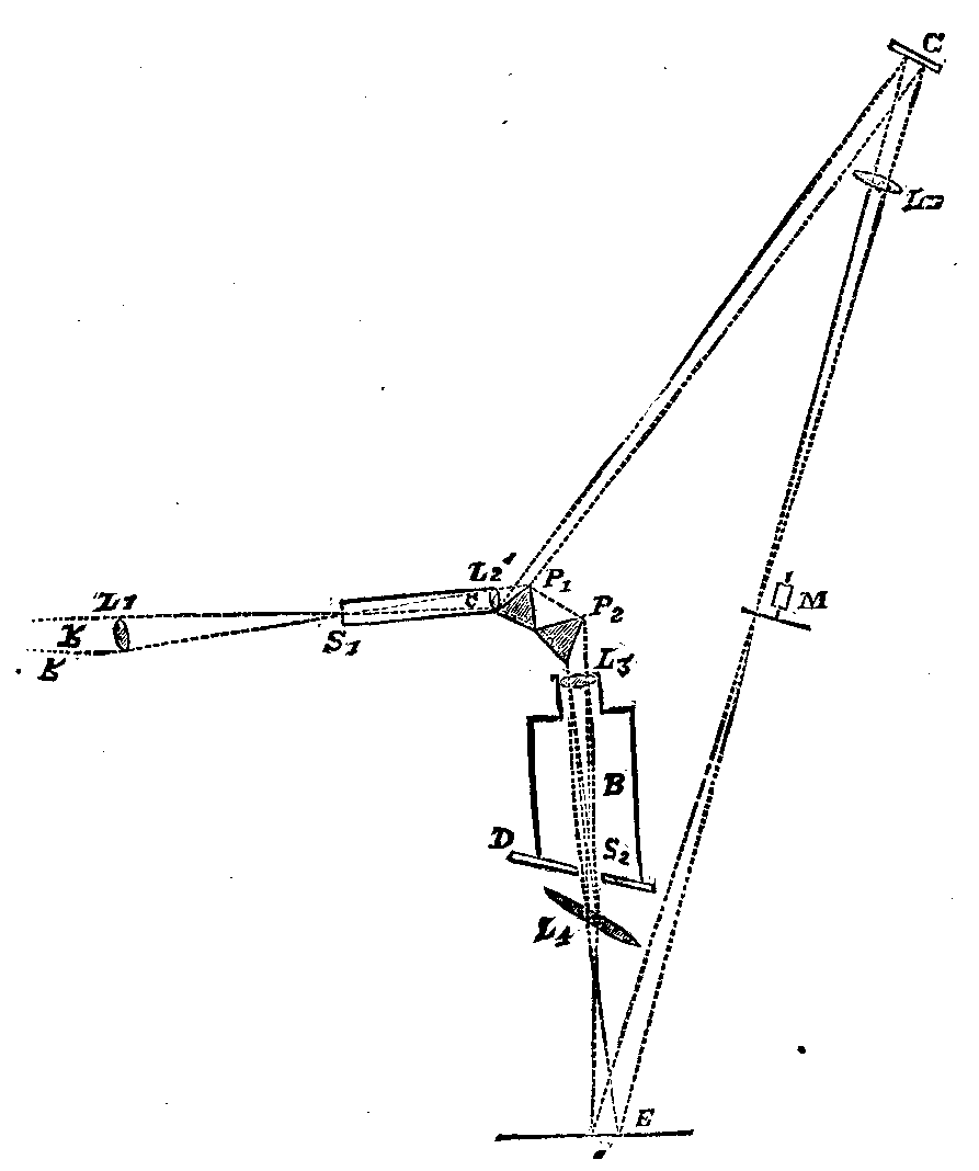
FIG. 1.—COLOR PHOTOMETER.
RR are rays (Fig. I) coming from the arc light, or, if we were using sunlight, from a heliostat, and a solar image is formed by a lens, L1, on the slit, S1 of the collimator, C. The parallel rays produced by the lens, L2, are partially refracted and partially reflected. The former pass through the prisms, P1P2, and are focused to form a spectrum by a lens, L3, on D, a movable ground glass screen. The rays are collected by a lens, L4, tilted at an angle as shown, to form a white image of the near surface of the second prism on F.
Passing a card with a narrow slit, S2, cut in it in front of the spectrum, any color which I may require can be isolated. The consequence is that, instead of the white patch upon the screen, I have a colored patch, the color of which I can alter to any hue lying between the red and the violet. Thus, then, we are able to get a real patch of very approximately homogeneous light to work with, and it is with these patches of color that I shall have to deal. Is there any way of measuring the brightness of these patches? was a question asked by General Festing and myself. After trying various plans, we hit upon the method I shall now show you, and if any one works with it he must become fascinated with it on account of its almost childish simplicity—a simplicity, I may remark, which it took us some months to find out. Placing a rod before the screen, it casts a black shadow surrounded with a colored background. Now I may cast another shadow from a candle or an incandescence lamp, and the two shadows are illuminated, one by the light of the colored patch and the other by the light from an incandescence lamp which I am using tonight. [Shown.] Now one stripe is evidently too dark. By an arrangement which I have of altering the resistance interposed between the battery and the lamp, I can diminish or increase the light from the lamp, first making the shadow it illuminates too light and then too dark compared with the other shadow, which is illuminated by the colored light. Evidently there is some position in which the shadows are equally luminous. When that point is reached, I can read off the current which is passing through the lamp, and having previously standardized it for each increment of current, I know what amount of light is given out. This value of the incandescence lamp I can use as an ordinate to a curve, the scale number which marks the position of the color in the spectrum being the abscissa. This can be done for each part of the spectrum, and so a complete curve can be constructed, which we call the illumination curve of the spectrum of the light under consideration.
Now, when we are working in the laboratory with a steady light, we may be at ease with this method, but when we come to working with light such as the sun, in which there may be constant variation, owing to passing, and may be usually imperceptible, mist, we are met with a difficulty; and in order to avoid this, General Festing and myself substituted another method, which I will now show you. We made the comparison light part of the light we were measuring. Light which enters the collimating lens partly passes through the prisms and is partly reflected from the first surface of the prism; that we utilize, thus giving a second shadow. The reflected rays from P1 fall on G, a silver on glass mirror. They are collected by L5, and form a white image of the prism also at F.
The method we can adopt of altering the intensity of the comparison light is by means of rotating sectors, which can be opened or closed at will, and the two shadows thus made equally luminous. [Shown.] But although this is an excellent plan for some purposes, we have found it better to adopt a different method. You will recollect that the brightest part of the spectrum is in the yellow, and that it falls off in brightness on each side, so instead of opening and closing the sectors, they are set at fixed intervals, and the slit is moved in front of the spectrum, just making the shadow cast by the reflected beam too dark or too light, and oscillating between the two till equality is discovered. The scale number is then noted, and the curve constructed as before. It must be remembered that, on each side of the yellow, equality can be established.
This method of securing a comparison light is very much better for sun work than any other, as any variation in the light whose spectrum is to be measured affects the comparison light in the same degree. Thus, suppose I interpose an artificial cloud before the slit of the spectroscope, having adjusted the two shadows, it will be seen that the passage of steam in front of the slit does not alter the relative intensities; but this result must be received with caution. [The lecturer then proceeded to point out the contrast colors that the shadow of the rod illuminated by white light assumed.]
I must now make a digression. It must not be assumed that every one has the same sense of color, otherwise there would be no color blindness. Part of the researches of General Festing and myself have been on the subject of color blindness, and these I must briefly refer to. We test all who come by making them match the luminosity of colors with white light, as I have now shown you. And as a color blind person has only two fundamental color perceptions instead of three, his matching of luminosities is even more accurate than is that made by those whose eyes are normal or nearly normal. It is curious to note how many people are more or less deficient in color perception. Some have remarked that it is impossible that they were color blind and would not believe it, and sometimes we have been staggered at first with the remarkable manner in which they recognized color to which they ultimately proved deficient in perception. For instance, one gentleman when I asked him the name of a red color patch, said it was sunset color. He then named green and blue correctly, but when I reverted to the red patch he said green.
On testing further, he proved totally deficient in the color perception of red, and with a brilliant red patch he matched almost a black shadow. The diagram shows you the relative perceptions in the spectrum of this gentleman and myself. There are others who only see three-quarters, others half, and others a quarter the amount of red that we see, while some see none. Others see less green and others less violet, but I have met with no one that can see more than myself or General Festing, whose color perceptions are almost identical. Hence we have called our curve of illumination the "normal curve."
We have tested several eminent artists in this manner, and about one half of the number have been proved to see only three quarters of the amount of red which we see. It might be thought that this would vitiate their powers of matching color, but it is not so. They paint what they see; and although they see less red in a subject, they see the same deficiency in their pigments; hence they are correct. If totally deficient, the case of course would be different.
Let us carry our experiments a step further, and see what effect what is known as a turbid medium has upon the illuminating value of different parts of the spectrum. I have here water which has been rendered turbid in a very simple manner. In it has been very cautiously dropped an alcoholic solution of mastic. Now mastic is practically insoluble in water, and directly the alcoholic solution comes in contact with the water it separates out in very fine particles, which, from their very fineness, remain suspended in the water. I propose now to make an experiment with this turbid water.
I place a glass cell containing water in front of the slit, and on the screen I throw a patch of blue light. I now change it for turbid water in a cell. This thickness much dims the blue; with a still greater thickness the blue has almost gone. If I measure the intensity of the light at each operation, I shall find that it diminishes according to a certain law, which is of the same nature as the law of absorption. For instance, if one inch diminishes the light one half, the next will diminish it half of that again, the next half of that again, while the fourth inch will cause a final diminution of the total light of one sixteenth. If the first inch allows only one quarter of the light, the next will only allow one sixteenth, and the fourth inch will only permit 1/256 part to pass.
Let us, however, take a red patch of light and examine it in the same way. We shall find that, when the greater thickness of the turbid medium we used when examining the blue patch of light is placed in front of the slit, much more of this light is allowed to pass than of the blue. If we measure the light, we shall find that the same law holds good as before, but that the proportion which passes is invariably greater with the red than the blue. The question then presents itself: Is there any connection between the amounts of the red and the blue which pass?
Lord Rayleigh, some years ago, made a theoretical investigation of the subject. But, as far as I am aware, no definite experimental proof of the truth of the theory was made till it was tested last year by General Festing and myself. His law was that for any ray, and through the same thickness, the light transmitted varied inversely as the fourth power of the wave length. The wave length 6,000 lies in the red, and the wave length 4,000 in the violet. Now 6,000 is to 4,000 as 3 to 2, and the fourth powers of these wave lengths are as 81 to 16, or as about 5 to 1. If, then, the four inches of our turbid medium allowed three quarters of this particular red ray to be transmitted, they would only allow (¾)5, or rather less than one fourth, of the blue ray to pass.
Now, this law is not like the law of absorption for ordinary absorbing media, such as colored glass for instance, because here we have an increased loss of light running from the red to the blue, and it matters not how the medium is made turbid, whether by varnish, suspended sulphur, or what not. It holds in every case, so long as the particles which make the medium turbid are small enough. And please to recollect that it matters not in the least whether the medium which is rendered turbid is solid, liquid, or air. Sulphur is yellow in mass, and mastic varnish is nearly white, while tobacco smoke when condensed is black, and very minute particles of water are colorless; it matters not what the color is, the loss of light is always the same. The result is simply due to the scattering of light by fine particles, such particles being small in dimensions compared with a wave of light. Now, in this trough is suspended 1/1000 of a cubic inch of mastic varnish, and the water in it measures about 100 cubic inches, or is 100,000 times more in bulk than the varnish. Under a microscope of ordinary power it is impossible to distinguish any particles of varnish; it looks like a homogeneous fluid, though we know that mastic will not dissolve in water.
Now a wave length in the red is about 1/40000 of an inch, and a little calculation will show that these particles are well within the necessary limits. Prof. Tyndall has delighted audiences here with an exposition of the effect of the scattering of light by small particles in the formation of artificial skies, and it would be superfluous for me to enter more into that. Suffice it to say that when particles are small enough to form the artificial blue sky, they are fully small enough to obey the above law, and that even larger particles will suffice. We may sum up by saying that very fine particles scatter more blue light than red light, and that consequently more red light than blue light passes through a turbid medium, and that the rays obey the law prescribed by theory.
I will exemplify this once more by using the whole spectrum and placing this cell, which contains hyposulphite of soda in solution in water, in front of the slit. By dropping in hydrochloric acid, the sulphur separates out in minute particles; and you will see that, as the particles increase in number, the violet, blue, green, and yellow disappear one by one and only red is left, and finally the red disappears itself.
Now let me revert to the question why the sun is red at sunset. Those who are lovers of landscape will have often seen on some bright summer's day that the most beautiful effects are those in which the distance is almost of a match to the sky. Distant hills, which when viewed close to are green or brown, when seen some five or ten miles away appear of a delicate and delicious, almost of a cobalt, blue color. Now, what is the cause of this change in color? It is simply that we have a sky formed between us and the distant ranges, the mere outline of which looms through it. The shadows are softened so as almost to leave no trace, and we have what artists call an atmospheric effect. If we go into another climate, such as Egypt or among the high Alps, we usually lose this effect. Distant mountains stand out crisp with black shadows, and the want of atmosphere is much felt. [Photographs showing these differences were shown.] Let us ask to what this is due. In such climates as England there is always a certain amount of moisture present in the atmosphere, and this moisture may be present as very minute particles of water—so minute indeed that they will sink down in an atmosphere of normal density—or as vapor. When present as vapor the air is much more transparent, and it is a common expression to use, that when distant hills look "so close" rain may be expected shortly to follow, since the water is present in a state to precipitate in larger particles. But when present as small particles of water the hills look very distant, owing to what we may call the haze between us and them. In recent weeks every one has been able to see very multiplied effects of such haze. The ends of long streets, for instance, have been scarcely visible, though the sun may have been shining, and at night the long vistas of gas lamps have shown light having an increasing redness as they became more distant. Every one admits the presence of mist on these occasions, and this mist must be merely a collection of intangible and very minute particles of suspended water. In a distant landscape we have simply the same or a smaller quantity of street mist occupying, instead of perhaps 1,000 yards, ten times that distance. Now I would ask, What effect would such a mist have upon the light of the sun which shone through it?
It is not in the bounds of present possibility to get outside our atmosphere and measure by the plan I have described to you the different illuminating values of the different rays, but this we can do: First, we can measure these values at different altitudes of the sun, and this means measuring the effect on each ray after passing through different thicknesses of the atmosphere, either at different times of day or at different times of the year, about the same hour. Second, by taking the instrument up to some such elevation as that to which Langley took his bolometer at Mount Whitney, and so to leave the densest part of the atmosphere below us.
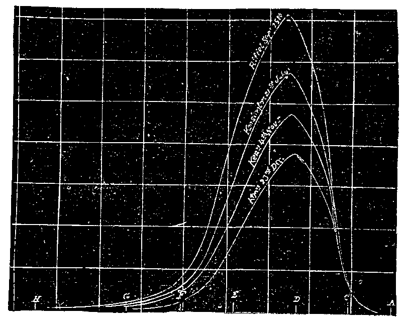
FIG. 2.—RELATIVE LUMINOSITIES.
Now, I have adopted both these plans. For more than a year I have taken measurements of sunlight in my laboratory at South Kensington, and I have also taken the instrument up to 8,000 feet high in the Alps, and made observations there, and with a result which is satisfactory in that both sets of observations show that the law which holds with artificially turbid media is under ordinary circumstances obeyed by sunlight in passing through our air: which is, you will remember, that more of the red is transmitted than of the violet, the amount of each depending on the wave length. The luminosity of the spectrum observed at the Riffel I have used as my standard luminosity, and compared all others with it. The result for four days you see in the diagram.
I have diagrammatically shown the amount of different colors which penetrated on the same days, taking the Riffel as ten. It will be seen that on December 23 we have really very little violet and less than half the green, although we have four fifths of the red.
The next diagram before you shows the minimum loss of light which I have observed for different air thicknesses. On the top we have the calculated intensities of the different rays outside our atmosphere. Thus we have that through one atmosphere, and two, three, and four. And you will see what enormous absorption there is in the blue end at four atmospheres. The areas of these curves, which give the total luminosity of the light, are 761, 662, 577, 503, and 439; and if observed as astronomers observe the absorption of light, by means of stellar observations, they would have had the values, 761, 664, 578, 504, and 439—a very close approximation one to the other.
Next notice in the diagram that the top of the curve gradually inclines to go to the red end of the spectrum as you get the light transmitted through more and more air, and I should like to show you that this is the case in a laboratory experiment. Taking a slide with a wide and long slot in it, a portion is occupied by a right angled prism, one of the angles of 45° being toward the center of the slot. By sliding this prism in front of the spectrum I can deflect outward any portion of the spectrum I like, and by a mirror can reflect it through a second lens, forming a patch of light on the screen overlapping the patch of light formed by the undeflected rays. If the two patches be exactly equal, white light is formed. Now, by placing a rod as before in front of the patch, I have two colored stripes in a white field, and though the background remains of the same intensity of white, the intensities of the two stripes can be altered by moving the right angled prism through the spectrum. The two stripes are now apparently equally luminous, and I see the point of equality is where the edge of the right angled prism is in the green. Placing a narrow cell filled with our turbid medium in front of the slit, I find that the equality is disturbed, and I have to allow more of the yellow to come into the patch formed by the blue end of the spectrum, and consequently less of it in the red end. I again establish equality. Placing a thicker cell in front, equality is again disturbed, and I have to have less yellow still in the red half, and more in the blue half. I now remove the cell, and the inequality of luminosity is still more glaring. This shows, then, that the rays of maximum luminosity must travel toward the red as the thickness of the turbid medium is increased.
The observations at 8,000 feet, here recorded, were taken on September 15, at noon, and of course in latitude 46° the sun could not be overhead, but had to traverse what would be almost exactly equivalent to the atmosphere at sea level. It is much nearer the calculated intensity for no atmosphere intervening than it is for one atmosphere. The explanation of this is easy. The air is denser at sea level than at 8,000 feet up, and the lower stratum is more likely to hold small water particles or dust in suspension than is the higher.
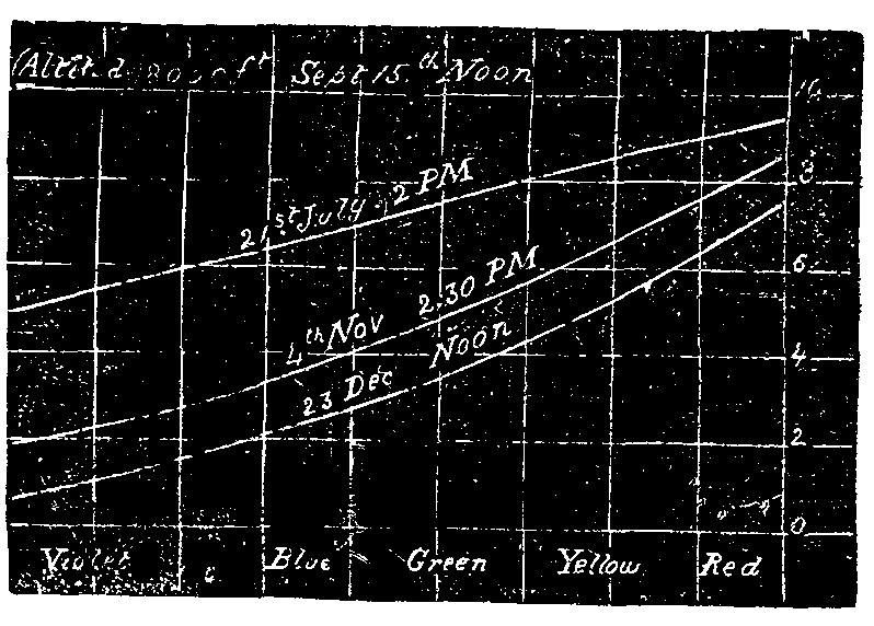
FIG. 3.—PROPORTIONS OF TRANSMITTED COLORS.
For, however small the particles may be, they will have a greater tendency to sink in a rare air than in a denser one, and less water vapor can be held per cubic foot. Looking, then, from my laboratory at South Kensington, we have to look through a proportionately larger quantity of suspended particles than we have at a high altitude when the air thicknesses are the same. And consequently the absorption is proportionately greater at sea level that at 8,000 feet high. This leads us to the fact that the real intensity of illumination of the different rays outside the atmosphere is greater than it is calculated from observations near sea level. Prof. Langley, in this theater, in a remarkable and interesting lecture, in which he described his journey up Mount Whitney to about 12,000 feet, told us that the sun was really blue outside our atmosphere, and at first blush the amount of extra blue which he deduced to be present in it would, he thought, make it so. But though he surmised the result from experiments made with rotating disks of colored paper, he did not, I think, try the method of using pure colors, and consequently, I believe, slightly exaggerated the blueness which would result.
I have taken Prof. Langley's calculations of the increase of intensity for the different rays, which I may say do not quite agree with mine, and I have prepared a mask which I can place in the spectrum, giving the different proportions of each ray as calculated by him, and this when placed in front of the spectrum will show you that the real color of sunlight outside the atmosphere, as calculated by Langley, can scarcely be called bluish. Alongside I place a patch of light which is very closely the color of sunlight on a July day at noon in England. This comparison will enable you to gauge the blueness, and you will see that it is not very blue, and, in fact, not bluer perceptibly than that we have at the Riffel, the color of the sunlight at which place I show in a similar way. I have also prepared some screens to show you the value of sunlight after passing through five and ten atmospheres. On an ordinary clear day you will see what a yellowness there is in the color. It seems that after a certain amount of blue is present in white light, the addition of more makes but little difference in the tint. But these last patches show that the light which passes through the atmosphere when it is feebly charged with particles does not induce the red of the sun as seen through a fog. It only requires more suspended particles in any thickness to induce it.
In observations made at the Riffel, and at 14,000 feet, I have found that it is possible to see far into the ultra-violet, and to distinguish and measure lines in the sun's spectrum which can ordinarily only be seen by the aid of a fluorescent eye piece or by means of photography. Circumstantial evidence tends to show that the burning of the skin, which always takes place in these high altitudes in sunlight, is due to the great increase in the ultra-violet rays. It may be remarked that the same kind of burning is effected by the electric arc light, which is known to be very rich in these rays.
Again, to use a homely phrase, "You cannot eat your cake and have it." You cannot have a large quantity of blue rays present in your direct sunlight and have a luminous blue sky. The latter must always be light scattered from the former. Now, in the high Alps you have, on clear day, a deep blue-black sky, very different indeed from the blue sky of Italy or of England; and as it is the sky which is the chief agent in lighting up the shadows, not only in those regions do we have dark shadows on account of no intervening—what I will call—mist, but because the sky itself is so little luminous. In an artistic point of view this is important. The warmth of an English landscape in sunlight is due to the highest lights being yellowish, and to the shadows being bluish from the sky light illuminating them. In the high Alps the high lights are colder, being bluer, and the shadows are dark, and chiefly illuminated by reflected direct sunlight. Those who have traveled abroad will know what the effect is. A painting in the Alps, at any high elevation, is rarely pleasing, although it may be true to nature. It looks cold, and somewhat harsh and blue.
In London we are often favored with easterly winds, and these, unpleasant in other ways, are also destructive of that portion of the sunlight which is the most chemically active on living organisms. The sunlight composition of a July day may, by the prevalence of an easterly wind, be reduced to that of a November day, as I have proved by actual measurement. In this case it is not the water particles which act as scatterers, but the carbon particles from the smoke.
Knowing, then, the cause of the change in the color of sunlight, we can make an artificial sunset, in which we have an imitation light passing through increasing thicknesses of air largely charged with water particles. [The image of a circular diaphragm placed in front of the electric light was thrown on the screen in imitation of the sun, and a cell containing hyposulphite of soda placed in the beam. Hydrochloric acid was then added; as the fine particles of sulphur were formed, the disk of light assumed a yellow tint, and as the decomposition of the hyposulphite progressed, it assumed an orange and finally a deep red tint.] With this experiment I terminate my lecture, hoping that in some degree I have answered the question I propounded at the outset—why the sun is red when seen through a fog.
[1]Before presenting any of the numerous difficulties in the way of accepting the wave theory of sound as correct, it will be best to briefly represent its teachings, so that the reader will see that the writer is perfectly familiar with the same.
The wave theory of sound starts off with the assumption that the atmosphere is composed of molecules, and that these supposed molecules are free to vibrate when acted upon by a vibrating body. When a tuning fork, for example, is caused to vibrate, it is assumed that the supposed molecules in front of the advancing fork are crowded closely together, thus forming a condensation, and on the retreat of the fork are separated more widely apart, thus forming a rarefaction. On account of the crowding of the molecules together to form the condensation, the air is supposed to become more dense and of a higher temperature, while in the rarefaction the air is supposed to become less dense and of lower temperature; but the heat of the condensation is supposed to just satisfy the cold of the rarefaction, in consequence of which the average temperature of the air remains unchanged.
The supposed increase of temperature in the condensation is supposed to facilitate the transference of the sound pulse, in consequence of which, sound is able to travel at the rate of 1,095 feet a second at 0°C., which it would not do if there was no heat generated.
In other words, the supposed increase of temperature is supposed to add 1/6 to the velocity of sound.
If the tuning fork be a Koenig C3 fork, which makes 256 full vibrations in one second, then there will be 256 sound waves in one second of a length of 1095/256 or 4.23 feet, so that at the end of a second of time from the commencement of the vibration, the foremost wave would have reached a distance of 1,095 feet, at 0°C.
The motion of a sound wave must not, however, be confounded with the motion of the molecules which at any moment form the wave; for during its passage every molecule concerned in its transference makes only a small excursion to and fro, the length of the excursion being the amplitude of vibration, on which the intensity of the sound depends.
Taking the same tuning fork mentioned above, the molecule would take 1/256 of a second to make a full vibration, which is the length of time it takes for the pulse to travel the length of the sound wave.
For different intensities, the amplitude of vibration of the molecule is roughly 1/50 to 1/1000000 of an inch. That is to say, in the case of the same tuning fork, the molecules it causes to vibrate must either travel a distance of 1/56 or 1/1000000 of an inch forward and back in the 1/256 of a second or in one direction in the 1/512 of a second.
I might further state that the pitch of the sound depends on the number of vibrations and the intensity, as already indicated by the amplitude of stroke—the timbre or quality of the sound depending upon factors which will be clearly set forth as we advance.
Having now clearly and correctly represented the wave theory of sound, without touching the physiological effect perceived by means of the ear, we will proceed to consider it.
We must first consider the state in which the supposed molecules exist in the air, before making progress.
The present science teaches that the diameter of the supposed molecules of the air is about 1/250000000 of an inch (Tait); that the distance between the molecules is about 8/100000 of an inch; that the velocity of the molecules is about 1,512 feet a second at O°C., in its free path; that the number of molecules in a cubic inch at O°C. is 3,505,519,800,000,000,000 or 35 followed by 17 ciphers (35)17; and that the number of collisions per second that the molecules make is, according to Boltzmann, for hydrogen, 17,700,000,000, that is to say, a hydrogen molecule in one second has its course wholly changed over seventeen billion times. Assuming seventeen billion or million to be right for the supposed air molecules, we have a very interesting problem to consider.
The wave theory of sound requires, if we expect to hear sound by means of a C3 fork of 256 vibrations, that the molecules of the air composing the sound wave must not be interfered with in such a way as to prevent them from traveling a distance of at least 1/50 to 1/1000000 of an inch forward and back in the 1/256 of a second. The problem we have to explain is, how a molecule traveling at the rate of 1,512 feet a second through a mean path of 8/100000 of an inch, and colliding seventeen billion or million times a second, can, by the vibration of the C3 fork, be made to vibrate so as to have a pendulous motion for 1/256 of a second and vibrate through a distance of 1/50 to the 1/1000000 of an inch without being changed or mar its harmonic motion.
It is claimed that the range of sound lies between 16 vibrations and 30,000 (about); in such extreme cases the molecules would require 1/16 and 1/30000 of a second to perform the same journey.
It must not be forgotten that a mass moving through a given distance has the power of doing work, and the amount of energy it will exercise will depend on its velocity. Now, a molecule of oxygen or nitrogen, according to modern science, is a mass 1/250000000 of an inch in diameter, and an oxygen molecule has been calculated to weigh 0.0000000054044 ounce. Taking this weight traveling with a velocity of 1,512 feet a second through an average distance of 8/100000 of an inch, the battering power or momentum it would have can be shown to be in round numbers capable of moving 1/200000 of an ounce.
Now, when the C3 tuning fork has been vibrating for some time, but still sounding audibly, Prof. Carter determined that its amplitude of stroke was only the 1/17000 of an inch, or its velocity of motion was at the rate of 1/33 of an inch in one second, or one inch in 33 seconds (over half a minute), or less than one foot in one hour.
Assuming one prong to weigh two ounces, we have a two-ounce mass moving 1/17000 of an inch with a velocity of 1/33 of an inch in one second. The prong, then, has a momentum or can exercise an amount of energy equivalent to 1/200 of an ounce, or can overcome the momentum of 1,000 molecules.
It would be difficult to discover not only how a locust can expend sufficient energy to impart to molecules of the air, so as to set them in a forced vibration, and thus enable a pulse of the energy imparted to control the motion of the supposed molecules of the air for a mile in all directions, but also to estimate the amount of energy the locust must expend.
According to the wave theory, a condensation and rarefaction are necessary to constitute a sound wave. Surely, if a condensation is not produced, there can be no sound wave! We have then no need to consider anything but the condensation or compression of the supposed air molecules, which will shorten the discussion. The property of mobility of the air and fluidity of water are well known. In the case of water, which is almost incompressible, this property is well marked, and unquestionably would be very nearly the same if water were wholly incompressible. In the case of the air, it is conceded by Tyndall, Thomson, Daniell, Helmholtz, and others that any compression or condensation of the air must be well marked or defined to secure the transmission of a sound pulse. The reason for this is on account of this very property of mobility. Tyndall says: "The prong of the fork in its swift advancement condenses the air." Thomson says: "If I move my hand vehemently through the air, I produce a condensation." Helmholtz says: "The pendulum swings from right to left with a uniform motion. Near to either end of its path it moves slowly, and in the middle fast. Among sonorous bodies which move in the same way, only very much faster, we may mention tuning forks." Tyndall says again: "When a common pendulum oscillates, it tends to form a condensation in front and a rarefaction behind. But it is only a tendency; the motion is so slow, and the air so elastic, that it moves away in front before it is sensibly condensed, and fills the space behind before it can become sensibly dilated. Hence waves or pulses are not generated by the pendulum." And finally, Daniell says: "A vibrating body, before it can act as a sounding body, must produce alternate compressions and rarefactions in the air, and these must be well marked. If, however, the vibrating body be so small that at each oscillation the surrounding air has time to flow round it, there is at every oscillation a local rearrangement—a local flow and reflow of the air; but the air at a distance is almost wholly unaffected by this."
Now, as Prof. Carter has shown by experiment that a tuning fork while still sounding had only an amplitude of swing of 1/17000 of an inch, and only traveled an aggregate distance of 1/33 of an inch in one second, or one inch in 33 seconds, surely such a motion is neither "swift," "fast," nor "vehement," and is unquestionably much "slower" than the motion of a pendulum. We have only to consider one forward motion of the prong, and if that motion cannot condense the air, then no wave can be produced; for after a prong has advanced and stopped moving (no matter for how short a time), if it has not compressed the air, its return motion (on the same side) cannot do anything toward making a compression. If one such motion of 1/17000 of an inch in 1/512 of a second cannot compress the air, then the remaining motions cannot. There is unquestionably a "union limit" between mobility and compressibility, and unless this limit is passed, mobility holds sway and prevents condensation or compression of the air; but when this limit is passed by the exercise of sufficient energy, then compression of the air results. Just imagine the finger to be moved through the air at a velocity of one foot in one hour; is it possible that any scientist who considers the problem in connection with the mobility of the air, could risk his reputation by saying that the air would be compressed? Heretofore it was supposed that a præong of a tuning fork was traveling fast because it vibrated so many times in a second, never stopping to think that its velocity of motion was entirely dependent upon the distance it traveled. At the start the prong travels 1/20 of an inch, but in a short time, while still sounding, the distance is reduced to 1/17000 of an inch. While the first motion was quite fast, about 25 inches in a second, the last motion was only about 1/33 of an inch in the same time, and is consequently 825 times slower motion. The momentum of the prong, the amount of work it can do, is likewise proportionately reduced.
Some seem to imagine, without thinking, that the elasticity of the air can add additional energy. This is perfectly erroneous; for elasticity is a mere property, which permits a body to be compressed on the application of a force, and to be dilated by the exercise of the force stored up in it by the compression. No property of the air can impart any energy. If the momentum of a molecule or a series of molecules extending in all directions for a mile is to be overcome so as to control the character of the movements of the molecules, then sufficient external energy must be applied to accomplish the task: and when we think that one cubic inch of air contains 3,505,519,800,000,000,000 molecules, to say nothing about the number in a cubic mile, which a locust can transmit sound through, we are naturally compelled to stop and think whether the vibrations of supposed molecules have anything or can have anything to do with the transference of sound through the air.
If control was only had of the distance the vibrating molecule travels from its start to the end of its journey, then only the intensity of the sound would be under subjection; but if at every infinitesimal instant control was had of its amplitude of swing, then the character, timbre, or quality of the sound is under subjection. It is evident, then, that the blows normally given by one molecule to another in their supposed constant bombardment must not be sufficient to alter the character of vibration a molecule set in oscillation by a sounding body must maintain, to preserve the timbre or quality of the sound in process of transmission; for if any such alteration should take place, then, naturally, while the pitch, and perhaps intensity, might be transmitted, the quality of the sound would be destroyed.
Again, it is certain that no molecule can perform two sets of vibrations, two separate movements, at the same time, any more than it can be in two places at the same time.
When a band of music is playing, the molecule is supposed to make a complex vibration, a resultant motion of all acting influences, which the ear is supposed to analyze. It remains for the mathematician to show how a molecule influenced by twenty or more degrees of applied energy, and twenty or more required number of frequences of vibration at the same time, can establish a resultant motion which will transmit the required pitch, intensity, and timbre of each instrument.
When a molecule is acted on by various forces, a resultant motion is unquestionably produced, but this would only tend to send the molecule forward and back in one direction, and, in fact, a direction it might have taken in the first place if hit properly.
How any resultant can be established as regards the time necessary for the molecule to take so as to complete a full vibration for the note C11, which requires 1/16 of a second, and for other notes up to C''''', which only requires 1/4176 of a second, as when an orchestra is playing, is certainly beyond human comprehension, if it is not beyond the "transcendental mathematics" of the present day.
Unquestionably, the able mathematicians Lord Rayleigh, Stokes, or Maxwell, if the problem was submitted to them, would start directly to work, and deduce by so called "higher mathematics" the required motions the molecules would have to undergo to accomplish this marvelous task—the same as they have established the diameter of the supposed molecules, their velocity, distance apart, and number of bombardments, without any shadow of positive proof that any such things as molecules exist.
As S. Caunizzana has said: "Some of the followers of the modern school push their faith to the borders of fanaticism; they often speak on molecular subjects with as much dogmatic assurance as though they had actually realized the ingenious fiction of Laplace, and had constructed a microscope by which they could detect the molecule and count the number of its constituent atoms."
Speaking of the "modern manufacturers of mathematical hypotheses," Mattieu Williams says: "It matters not to them how 'wild and visionary,' how utterly gratuitous, any assumption may be, it is not unscientific provided it can be vested in formulæ and worked out mathematically.
"These transcendental mathematicians are struggling to carry philosophy back to the era of Duns Scotus, when the greatest triumph of learning was to sophisticate so profoundly an obvious absurdity that no ordinary intellect could refute it.... The close study of pure mathematics, by directing the mind to processes of calculation rather than to phenomena, induces that sublime indifference to facts which has characterized the purely mathematical intellect of all ages."
Tyndall, however, states in all frankness, and without the aid of mathematical considerations, that "when we try to visualize the motions of the air having one thousand separate tones, to present to the eye of the mind the battling of the pulses, direct and reverberated, the imagination retires baffled at the attempt;" and he might have added, the shallowness and fallacy of the wave theory of sound was made apparent. He, however, does express himself as follows: "Assuredly, no question of science ever stood so much in need of revision as this of the transmission of sound through the atmosphere. Slowly but surely we mastered the question, and the further we advance, the more plainly it appeared that our reputed knowledge regarding it was erroneous from beginning to end."
Until physicists are willing to admit that the physical forces of nature are objective things—actual entities, and not mere modes of motion—a full and clear comprehension of the phenomena of nature will never be revealed to them. The motion of all bodies, whether small or great, is due to the entitative force stored up in them, and the energy they exercise is in proportion to the stored-up force.
Tyndall says that "heat itself, its essence and quiddity, IS MOTION, AND NOTHING ELSE." Surely, no scientist who considers what motion is can admit such a fallacious statement, for motion is simply "position in space changing;" it is a phenomenon, the result of the application of entitative force to a body. It is no more an entity than shadow, which is likewise a phenomenon. Motion, per se, is nothing and can do nothing in physics. Matter and force are the two great entities of the universe—both being objective things. Sound, heat, light, electricity, etc., are different forms of manifestation of an all-pervading force element—substantial, yet not material.
[NATURE.]
Mr. Thiselton Dyer has rendered a great service, not only to botanists, but also to physicists and mineralogists, by recalling attention to the very interesting substance known as "tabasheer." As he truly states, very little fresh information has been published on the subject during recent years, a circumstance for which I can only account by the fact that botanists may justly feel some doubt as to whether it belongs to the vegetable kingdom, while mineralogists seem to have equal ground for hesitation in accepting it as a member of the mineral kingdom.
It is very interesting to hear that so able a physiologist as Prof. Cohn intends to investigate the conditions under which living plants separate this substance from their tissues. That unicellular algae, like the Diatomaceæ, living in a medium which may contain only one part in 10,000 by weight of dissolved silica, or even less than that amount, should be able to separate this substance to form their exquisitely ornamented frustules is one of the most striking facts in natural history, whether we regard it in its physiological or its chemical aspects.
Sir David Brewster long ago pointed out the remarkable physical characters presented by the curious product of the vegetable world known as "tabasheer," though so far as I can find out it has not in recent years received that attention from physicists which the experiments and observations of the great Scotch philosopher show it to be worthy of.
Tabasheer seems to stand in the same relation to the mineral kingdom as do ambers and pearls. It is in fact an opal formed under somewhat remarkable and anomalous conditions which we are able to study; and in this aspect I have for some time past been devoting a considerable amount of attention to the minute structure of the substance by making thin sections and examining them under the microscope. It may be as well, perhaps, to give a short sketch of the information upon the subject which I have up to the present time been able to obtain, and in this way to call attention to points upon which further research seems to be necessary.
From time immemorial tabasheer has enjoyed a very high reputation in Eastern countries as a drug. Its supposed medicinal virtues, like those of the fossil teeth of China and the belemnites ("thunderbolts") of this country, seem to have been suggested by the peculiarity of its mode of occurrence. A knowledge of the substance was introduced into Western Europe by the Arabian physicians, and the name by which the substance is generally known is said to be of Arabic origin. Much of the material which under the name of "tabasheer" finds its way to Syria and Turkey is said, however, to be fictitious or adulterated.
In 1788 Dr. Patrick Russell, F.R.S., then resident at Vizagapatam, wrote a letter to Sir Joseph Banks in which he gave an account of all the facts which he had been able to collect with respect to this curious substance and its mode of occurrence, and his interesting letter was published in the Philosophical Transactions for 1790 (vol. lxxx., p. 273).
Tabasheer is said to be sometimes found among the ashes of bamboos that have been set on fire (by mutual friction?). Ordinarily, however, it is sought for by splitting open those bamboo stems which give a rattling sound when shaken. Such rattling sounds do not, however, afford infallible criteria as to the presence or absence of tabasheer in a bamboo, for where the quantity is small it is often found to be closely adherent to the bottom and sides of the cavity. Tabasheer is by no means found in all stems or in all joints of the same stem of the bamboos. Whether certain species produce it in greater abundance than others, and what is the influence of soil, situation, and season upon the production of the substance, are questions which do not seem as yet to have been accurately investigated.
Dr. Russell found that the bamboos which produce tabasheer often contain a fluid, usually clear, transparent, and colorless or of greenish tint, but sometimes thicker and of a white color, and at other times darker and of the consistency of honey. Occasionally the thicker varieties were found passing into a solid state, and forming tabasheer.
Dr. Russell performed the interesting experiment of drawing off the liquid from the bamboo stem and allowing it to stand in stoppered bottles. A "whitish, cottony sediment" was formed at the bottom, with a thin film of the same kind at the top. When the whole was well shaken together and allowed to evaporate, it left a residue of a whitish brown color resembling the inferior kinds of tabasheer. By splitting up different joints of bamboo Dr. Russell was also able to satisfy himself of the gradual deposition within them of the solid tabasheer by the evaporation of the liquid solvent.
In 1791, Mr. James Louis Macie, F.R.S. (who afterward took the name of Smithson), gave an account of his examination of the properties of the specimens of tabasheer sent home by Dr. Russell (Phil. Trans., vol. lxxxi., 1791, p. 368). These specimens came from Vellore, Hyderabad, Masulipatam, and other localities in India. They were submitted to a number of tests which induced Mr. Macie to believe that they consisted principally of silica, but that before calcination some vegetable matter must have been present. A determination of the specific gravity of the substance by Mr. Macie gave 2.188 as the result. Another determination by Mr. Cavendish gave 2.169.
In this same paper it is stated that a bamboo grown in a hot-house at Islington gave a rattling noise, and on being split open by Sir Joseph Banks yielded, not an ordinary tabasheer, but a small pebble about the size of half a pea, externally of a dark brown or black color, and within of a reddish brown tint. This stone is said to have been so hard as to cut glass, and to have been in parts of a crystalline structure. Its behavior with reagents was found to be different in many respects from that of the ordinary tabasheer; and it was proved to contain silica and iron. The specimen is referred to in a letter to Berthollet published in the Annales de Chimie for the same year (October, 1791). There may be some doubt as to whether this specimen was really of the nature of tabasheer. If such were the case, it would seem to have been a tabasheer in which a crystalline structure had begun to be set up.
In the year 1806, MM. Foureroy and Vauquelin gave an account of a specimen of tabasheer brought from South America in 1804 by Humboldt and Bonpland (Mem. de l'Inst., vol. vi., p. 382). It was procured from a species of bamboo growing on the west of Pichincha, and is described as being of a milk white color, in part apparently crystalline in structure, and in part semi-transparent and gelatinous. It was seen to contain traces of the vegetable structure of the plant from which it had been extracted. On ignition it became black, and emitted pungent fumes.
An analysis of this tabasheer from the Andes showed that it contained 70 per cent. of silica and 30 per cent. of potash, lime, and water, with some organic matter. It would, perhaps, be rash to conclude from this single observation that the American bamboo produced tabasheer of different composition from that of the Old World; but the subject is evidently one worthy of careful investigation.
It was in the year 1819 that Sir David Brewster published the first account of his long and important series of observations upon the physical peculiarities of tabasheer (Phil. Trans., vol. cix., 1819, p. 283). The specimens which he first examined were obtained from India by Dr. Kennedy, by whom they were given to Brewster.
Brewster found the specimens which he examined to be perfectly isotropic, exercising no influence in depolarizing light. When heated, however, it proved to be remarkably phosphorescent. The translucent varieties were found to transmit a yellowish and to reflect a bluish white light—or, in other words, to exhibit the phenomenon of opalescence. When tabasheer is slightly wetted, it becomes white and opaque; but when thoroughly saturated with water, perfectly transparent.
By preparing prisms of different varieties of tabasheer, Brewster proceeded to determine its refractive index, arriving at the remarkable result that tabasheer "has a lower index of refraction than any other known solid or liquid, and that it actually holds an intermediate place between water and gaseous bodies!" This excessively low refractive power Brewster believes to afford a complete explanation of the extraordinary behavior exhibited by tabasheer when wholly or partially saturated with fluids. A number of interesting experiments were performed by saturating the tabasheer with oils of different refractive powers, and by heating it in various ways and under different conditions, and also by introducing carbonaceous matter into the minute pores of the substance by setting fire to paper in which fragments were wrapped.
The mean of experiments undertaken by Mr. James Jardine, on behalf of Brewster, for determining the specific gravity of tabasheer, gave as a result 2.235. From these experiments Brewster concluded that the space occupied by the pores of the tabasheer is about two and a half times as great as that of the colloid silica itself!
From this time forward Brewster seems to have manifested the keenest interest in all questions connected with the origin and history of a substance possessing such singular physical properties. By the aid of Mr. Swinton, secretary to the government at Calcutta, he formed a large and interesting collection of all the different varieties of tabasheer from various parts of India. He also obtained specimens of the bamboo with the tabasheer in situ. In 1828 he published an interesting paper on "The Natural History and Properties of Tabasheer" (Edinburgh Journal of Science, vol. viii., 1828, p. 288), in which he discussed many of the important problems connected with the origin of the substance. From his inquiries and observations, Brewster was led to conclude that tabasheer was only produced in those joints of bamboos which are in an injured, unhealthy, or malformed condition, and that the siliceous fluid only finds its way into the hollow spaces between the joints of the stem when the membrane lining the cavities is destroyed or rent by disease.
Prof. Edward Turner, of the University of London, undertook an analysis of tabasheer, the specimens being supplied from Brewster's collection (Edinburgh Journal of Science, vol. viii., 1828, p. 335). His determinations of the specific gravities of different varieties were as follows:
Chalky tabasheer.         2.189
Translucent tabasheer.    2.167
Transparent tabasheer.    2.160
All the varieties lose air and hygroscopic water at 100° C., and a larger quantity of water and organic matter (indicated by faint smoke and an empyreumatic odor) at a red heat. The results obtained were as follows:
                       Loss at 100° C.   Loss at red heat.
Chalky tabasheer.      0.838 per cent.   1.277 per cent.
Translucent tabasheer. 1.620  "   "      3.840  "   "
Transparent tabasheer. 2.411  "   "      4.518  "   "
Dr. Turner found the ignited Indian tabasheer to consist almost entirely of pure silica with a minute quantity of lime and vegetable matter. He failed to find any trace of alkalies in it.
In 1855, Guibourt (Journ. de Pharm. [3], xxvii., 81, 161, 252; Phil. Mag, [4], x., 229) analyzed a specimen of tabasheer having a specific gravity of 2.148. It gave the following result:
Silica.            = 96.94
Potash and lime.   =  0.13
Water.             =  2.93
Organic matter.    = trace
Guibourt criticised some of the conclusions arrived at by Brewster, and sought to explain the source of the silica by studying the composition of different parts of the bamboo. While the ashes of the wood contained 0.0612 of the whole weight of the wood, the pith was found to contain 0.448 per cent., the inner wood much less, and the greatest proportion occurred in the external wood. On these determinations Guibourt founded a theory of the mode of formation of tabasheer based on the suggestion that at certain periods of its growth the bamboo needed less silica than at other times, and that when not needed, the silica was carried inward and deposited in the interior.
In the year 1857, D.W. Host van Tonningen, of Buitenzorg, undertook an investigation of the tabasheer of Java, which is known to the natives of that island under the name of "singkara" (Naturkundig Tijdschrift voor Nederlandsch Indie, vol. xiii., 1857, p. 391). The specimens examined were obtained from the Bambusa apus, growing in the Residency of Bantam. It is described as resembling in appearance the Indian tabasheers. Its analysis gave the following result:
Silica.          = 86.387
Iron oxide.      =  0.424
Lime.            =  0.244
Potash.          =  4.806
Organic matter.  =  0.507
Water.           =  7.632
                   ------
Total.            100.000
Apart from the question of its singular mode of origin, however, and its remarkable and anomalous physical properties, tabasheer is of much interest to mineralogists and geologists. All the varieties hitherto examined, with the exception of the peculiar one from the Andes, are in composition and physical characters true opals. This is the case with all the Indian and Java varieties. They consist essentially of silica in its colloidal form, the water, lime, potash, and organic matter being as small and variable in amount as in the mineral opals; and, as in them, these substances must be regarded merely as mechanical impurities.
The tabasheers must be studied in their relations on the one hand with certain varieties of the natural semi-opals, hydrophanes, beekites, and floatstones, some of which they closely resemble in their physical characters, and on the other hand with specimens of artificially deposited colloid silica formed under different conditions. Prof. Church, who has so successfully studied the beekites, informs me that some of those remarkable bodies present singular points of analogy with tabasheer.
By the study of thin sections I have, during several years, been endeavoring to trace the minute structure of some of these substances. In no class of materials is it more necessary to guard one's self against errors of observation arising from changes induced in the substance during the operations which are necessary to the preparation of transparent sections of hard substances. Unfortunately, too, it is the custom of the natives to prepare the substance for the market by an imperfect calcination, and hitherto I have only been able to study specimens procured in the markets which have been subjected to this process. It is obviously desirable, before attempting to interpret the structures exhibited, under the microscope, to compare the fresh and uncalcined materials with those that have been more or less altered by heat.
Tabasheer would seem, from Brewster's experiments, to be a very intimate admixture of two and a half parts of air with one part of colloidal silica. The interspaces filled with air appear, at all events, in most cases, to be so minute that they cannot be detected by the highest powers of the microscope which I have been able to employ. It is this intimate admixture of a solid with a gas which probably gives rise to the curious and anomalous properties exhibited by this singular substance.
The ultra-microscopical vesicles filled with air in all probability give rise to the opalescence which is so marked a property of the substance. Their size is such as to scatter and throw back the rays at the blue end of the spectrum and to transmit those at the red end.
When the vesicles of the substance are filled with Canada balsam, and a thin slice is cut from it, this opalescence comes out in the most striking manner. Very thin sections are of a rich orange yellow by transmitted light, and a delicate blue tint by reflected light. I do not know of any substance which in such thin films displays such striking opalescence.
That the excessively low refractive power of tabasheer is connected with the mechanical admixture of the colloidal silica with air seems to be proved by the experiments of Brewster, showing that with increase of density there was an increase in the refractive index from 1.111 in specimens of the lowest specific gravity to 1.182 in those of the highest specific gravity. Where the surface was hard and dense, Brewster found the refractive index to approach that of semi opal. The wonderful thing is that a substance so full of cavities containing gas should nevertheless be transparent.
By the kindness of Mr. F. Rutley, F.G.S., I am able to supply a drawing taken from one of my sections of tabasheer.
The accompanying woodcut gives some idea of the interesting structures exhibited in some sections of tabasheer, though much of the delicacy and fidelity of the original drawing has been lost in transferring it to the wood.
In this particular case, the faint punctation of the surface may possibly indicate the presence of air vesicles of a size sufficiently great to be visible under the microscope. But in many other instances I have failed to detect any such indication, even with much higher powers. The small ramifying tubules might at first sight be taken for some traces of a vegetable tissue, but my colleague, Dr. Scott, assures me that they do not in the least resemble any tissue found in the bamboo. I have myself no doubt that it is an inorganic structure. It is not improbably analogous to the peculiar ramifying tubules formed in a solution of water glass when a crystal of copper sulphate is suspended in it, as shown by Dr. Heaton (Proc. Brit. Assoc., 1869, p. 127). Similar forms also occur on a larger scale in some agates, and the artificial cells of Traube may probably be regarded as analogous phenomena.
The aggregates of globular bodies seen in the section so greatly resemble the globulites of slags and natural glasses, and in their arrangement so forcibly recall the structures seen in the well known pitchstone of Corriegills in Arran, that one is tempted to regard them as indicating the beginnings of the development of crystalline structure in the tabasheer. But I have good grounds for believing the structure to have a totally different origin. They seem in fact to be the portions of the mass which the fluid Canada balsam has not succeeded in penetrating. By heating they may be made to grow outward, and as more balsam is imbibed they gradually diminish, and finally disappear.
I must postpone till a future occasion a discussion of all the structures of this remarkable substance and of the resemblances and differences which they present to the mineral opals on the one hand, and to those of the opals of animal origin found in sponge spicules, radiolarians, and the rocks formed from them, some of which have recently been admirably investigated by Dr. G.J. Hinde (Phil. Trans., 1885, pp. 425-83).
I cannot, however, but think that it would be of the greatest service to botanists, physicists, and mineralogists alike, if some resident in India would resume the investigations so admirably commenced by Dr. Patrick Russell nearly a century ago; and it is in the hope of inducing some one to undertake this task that I have put together these notes. There are certain problems with regard to the mode of occurrence of this singular substance which could only be solved by an investigator in the country where it is found.
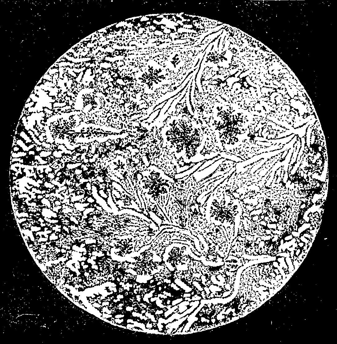
SECTION OF INDIAN TABASHEER, SEEN WITH A MAGNIFYING POWER OF 250 DIAMETERS.
Most parcels of the commercial tabasheer appear to contain different varieties, from the white, opaque, chalk like forms through the translucent kinds to those that are perfectly transparent. It would be of much interest if the exact relation and modes of origin of these different varieties could be traced. It would also be important to determine if Brewster was right in his conclusion that the particular internodes of a bamboo which contain tabasheer always have their inner lining tissue rent or injured. The repetition of Dr. Russell's experiment of drawing off the liquids from the joints of bamboos and allowing them to evaporate is also greatly to be desired. My colleague, Prof. Rucker, F.R.S., has kindly undertaken to re-examine the results arrived at by Brewster in the light of more recent physical investigations, and I doubt not that some of the curious problems suggested by this very remarkable substance may ere long find a solution.
JOHN W. JUDD.
In 1883 Mr. Hekmeyer, pharmaceutist in chief of the Dutch Indies, exhibited at Amsterdam some specimens of Javanese edible earth, both in a natural state and in the form of various natural objects. A portion of this collection he has placed at our disposal, and has given us some information regarding its nature, use, etc.
These clays, which are eaten not only in Java, but also in Sumatra, New Caledonia, Siberia, Guiana, Terra del Fuego, etc., are essentially composed of silex, alumina, and water in variable proportions, and are colored with various metallic oxides. They are in amorphous masses, are unctuous to the touch, stick to the tongue, and form a fine, smooth paste with water. The natives of Java and Sumatra prepare them in a peculiar way. They free them of foreign substances, spread them out in thin sheets, which they cut into small pieces and parch in an iron saucepan over a coal fire.
Each of these little cakes, when shrunken up into a little roll, looks somewhat like a grayish or reddish fragment of cinnamon bark. The clay is also formed into imitations of various objects.
We have tasted this Javanese dainty, and we must very humbly confess that we have found nothing attractive in the earthy and slightly empyreumatic taste of this singular food. However, a sweet and slightly aromatic taste that follows the first impression is an extenuating circumstance.
According to the account given by Labillardiere, confirmed by the information given by Mr. Hekmeyer, the figures are often craunched by women and children, to the latter of whom they serve as dolls, toys, and even money-boxes, as shown by the slits formed in the upper part of the larger objects, which are usually hollow.
We have not sufficient documents to carry us back to the origin of that tradition that would have it that the human form has been given to certain food preparations from remote times. Savants will not be slow to see in this a vague relic of the horrible festivities that succeeded human sacrifices among primitive peoples. For want of prisoners and of designated victims, a symbolic representation would have gradually developed, and been kept up, though losing its religious character. We merely call brief attention to this obscure problem, not having the pretension to solve it.—Revue d'Ethnographie.
A catalogue, containing brief notices of many important scientific papers heretofore published in the SUPPLEMENT, may be had gratis at this office.
Terms of Subscription, $5 a Year.
Sent by mail, postage prepaid, to subscribers in any part of the United States or Canada. Six dollars a year, sent, prepaid, to any foreign country.
All the back numbers of THE SUPPLEMENT, from the commencement, January 1, 1876, can be had. Price, 10 cents each.
All the back volumes of THE SUPPLEMENT can likewise be supplied. Two volumes are issued yearly. Price of each volume, $2.50, stitched in paper, or $3.50, bound in stiff covers.
COMBINED RATES—One copy of SCIENTIFIC AMERICAN and one copy of SCIENTIFIC AMERICAN SUPPLEMENT, one year, postpaid, $7.00.
A liberal discount to booksellers, news agents, and canvassers.
MUNN & CO., Publishers,
361 Broadway, New York, N.Y.
In connection with the Scientific American, Messrs. MUNN & Co. are Solicitors of American and Foreign Patents, have had 42 years' experience, and now have the largest establishment in the world. Patents are obtained on the best terms.
A special notice is made in the Scientific American of all Inventions patented through this Agency, with the name and residence of the Patentee. By the immense circulation thus given, public attention is directed to the merits of the new patent, and sales or introduction often easily effected.
Any person who has made a new discovery or invention can ascertain, free of charge, whether a patent can probably be obtained, by writing to MUNN & Co.
We also send free our Hand Book about the Patent Laws, Patents, Caveats. Trade Marks, their costs, and how procured. Address
MUNN & CO., 361 Broadway, New York.
Branch Office, 622 and 624 F St., Washington, D.C.
$2.50 a Year. Single Copies, 25 Cents.
This is a Special Edition of THE SCIENTIFIC AMERICAN, issued monthly—on the first day of the month. Each number contains about forty large quarto pages, equal to about two hundred ordinary book pages, forming, practically, a large and splendid Magazine of Architecture, richly adorned with elegant plates in colors and with fine engravings; illustrating the most interesting examples of modern Architectural Construction and allied subjects.
A special feature is the presentation in each number of a variety of the latest and best plans for private residences, city and country, including those of very moderate cost as well as the more expensive. Drawings in perspective and in color are given, together with full Plans, Specifications, Costs, Bills of Estimate, and Sheets of Details.
No other building paper contains so many plans, details, and specifications regularly presented as the SCIENTIFIC AMERICAN. Hundreds of dwellings have already been erected on the various plans we have issued during the past year, and many others are in process of construction.
Architects, Builders, and Owners will find this work valuable in furnishing fresh and useful suggestions. All who contemplate building or improving homes, or erecting structures of any kind, have before them in this work an almost endless series of the latest and best examples from which to make selections, thus saving time and money.
Many other subjects, including Sewerage, Piping, Lighting, Warming, Ventilating, Decorating, Laying out of grounds, etc., are illustrated. An extensive Compendium of Manufacturers' Announcements is also given, in which the most reliable and approved Building Materials, Goods, Machines, Tools, and Appliances are described and illustrated, with addresses of the makers, etc.
The fullness, richness, cheapness, and convenience of this work have won for it the Largest Circulation of any Architectural publication in the world.
MUNN & CO., Publishers, 361 Broadway, New York.
A Catalogue of valuable books on Architecture, Building, Carpentry, Masonry, Heating, Warming, Lighting, Ventilation, and all branches of industry pertaining to the art of Building, is supplied free of charge, sent to any address.
In connection with the publication of the BUILDING EDITION of the SCIENTIFIC AMERICAN, Messrs. Munn & Co. furnish plans and specifications for buildings of every kind, including Churches, Schools, Stores, Dwellings, Carriage Houses, Barns, etc.
In this work they are assisted by able and experienced architects. Full plans, details, and specifications for the various buildings illustrated in this paper can be supplied.
Those who contemplate building, or who wish to alter, improve, extend, or add to existing buildings, whether wings, porches, bay windows, or attic rooms, are invited to communicate with the undersigned. Our work extends to all parts of the country. Estimates, plans, and drawings promptly prepared. Terms moderate. Address
MUNN & CO., 361 Broadway, New York.
End of the Project Gutenberg EBook of Scientific American Supplement, No.
595, May 28, 1887, by Various

*** END OF THIS PROJECT GUTENBERG EBOOK SCIENTIFIC AMERICAN SUPPL. 595 ***

***** This file should be named 11648-h.htm or 11648-h.zip *****
This and all associated files of various formats will be found in:
        https://www.gutenberg.org/1/1/6/4/11648/

Produced by by Don Kretz, Juliet Sutherland, Charles Franks and the
DP Team


Updated editions will replace the previous one--the old editions
will be renamed.

Creating the works from public domain print editions means that no
one owns a United States copyright in these works, so the Foundation
(and you!) can copy and distribute it in the United States without
permission and without paying copyright royalties.  Special rules,
set forth in the General Terms of Use part of this license, apply to
copying and distributing Project Gutenberg-tm electronic works to
protect the PROJECT GUTENBERG-tm concept and trademark.  Project
Gutenberg is a registered trademark, and may not be used if you
charge for the eBooks, unless you receive specific permission.  If you
do not charge anything for copies of this eBook, complying with the
rules is very easy.  You may use this eBook for nearly any purpose
such as creation of derivative works, reports, performances and
research.  They may be modified and printed and given away--you may do
practically ANYTHING with public domain eBooks.  Redistribution is
subject to the trademark license, especially commercial
redistribution.


*** START: FULL LICENSE ***

THE FULL PROJECT GUTENBERG LICENSE
PLEASE READ THIS BEFORE YOU DISTRIBUTE OR USE THIS WORK

To protect the Project Gutenberg-tm mission of promoting the free
distribution of electronic works, by using or distributing this work
(or any other work associated in any way with the phrase "Project
Gutenberg"), you agree to comply with all the terms of the Full Project
Gutenberg-tm License (available with this file or online at
https://gutenberg.org/license).


Section 1.  General Terms of Use and Redistributing Project Gutenberg-tm
electronic works

1.A.  By reading or using any part of this Project Gutenberg-tm
electronic work, you indicate that you have read, understand, agree to
and accept all the terms of this license and intellectual property
(trademark/copyright) agreement.  If you do not agree to abide by all
the terms of this agreement, you must cease using and return or destroy
all copies of Project Gutenberg-tm electronic works in your possession.
If you paid a fee for obtaining a copy of or access to a Project
Gutenberg-tm electronic work and you do not agree to be bound by the
terms of this agreement, you may obtain a refund from the person or
entity to whom you paid the fee as set forth in paragraph 1.E.8.

1.B.  "Project Gutenberg" is a registered trademark.  It may only be
used on or associated in any way with an electronic work by people who
agree to be bound by the terms of this agreement.  There are a few
things that you can do with most Project Gutenberg-tm electronic works
even without complying with the full terms of this agreement.  See
paragraph 1.C below.  There are a lot of things you can do with Project
Gutenberg-tm electronic works if you follow the terms of this agreement
and help preserve free future access to Project Gutenberg-tm electronic
works.  See paragraph 1.E below.

1.C.  The Project Gutenberg Literary Archive Foundation ("the Foundation"
or PGLAF), owns a compilation copyright in the collection of Project
Gutenberg-tm electronic works.  Nearly all the individual works in the
collection are in the public domain in the United States.  If an
individual work is in the public domain in the United States and you are
located in the United States, we do not claim a right to prevent you from
copying, distributing, performing, displaying or creating derivative
works based on the work as long as all references to Project Gutenberg
are removed.  Of course, we hope that you will support the Project
Gutenberg-tm mission of promoting free access to electronic works by
freely sharing Project Gutenberg-tm works in compliance with the terms of
this agreement for keeping the Project Gutenberg-tm name associated with
the work.  You can easily comply with the terms of this agreement by
keeping this work in the same format with its attached full Project
Gutenberg-tm License when you share it without charge with others.

1.D.  The copyright laws of the place where you are located also govern
what you can do with this work.  Copyright laws in most countries are in
a constant state of change.  If you are outside the United States, check
the laws of your country in addition to the terms of this agreement
before downloading, copying, displaying, performing, distributing or
creating derivative works based on this work or any other Project
Gutenberg-tm work.  The Foundation makes no representations concerning
the copyright status of any work in any country outside the United
States.

1.E.  Unless you have removed all references to Project Gutenberg:

1.E.1.  The following sentence, with active links to, or other immediate
access to, the full Project Gutenberg-tm License must appear prominently
whenever any copy of a Project Gutenberg-tm work (any work on which the
phrase "Project Gutenberg" appears, or with which the phrase "Project
Gutenberg" is associated) is accessed, displayed, performed, viewed,
copied or distributed:

This eBook is for the use of anyone anywhere at no cost and with
almost no restrictions whatsoever.  You may copy it, give it away or
re-use it under the terms of the Project Gutenberg License included
with this eBook or online at www.gutenberg.org

1.E.2.  If an individual Project Gutenberg-tm electronic work is derived
from the public domain (does not contain a notice indicating that it is
posted with permission of the copyright holder), the work can be copied
and distributed to anyone in the United States without paying any fees
or charges.  If you are redistributing or providing access to a work
with the phrase "Project Gutenberg" associated with or appearing on the
work, you must comply either with the requirements of paragraphs 1.E.1
through 1.E.7 or obtain permission for the use of the work and the
Project Gutenberg-tm trademark as set forth in paragraphs 1.E.8 or
1.E.9.

1.E.3.  If an individual Project Gutenberg-tm electronic work is posted
with the permission of the copyright holder, your use and distribution
must comply with both paragraphs 1.E.1 through 1.E.7 and any additional
terms imposed by the copyright holder.  Additional terms will be linked
to the Project Gutenberg-tm License for all works posted with the
permission of the copyright holder found at the beginning of this work.

1.E.4.  Do not unlink or detach or remove the full Project Gutenberg-tm
License terms from this work, or any files containing a part of this
work or any other work associated with Project Gutenberg-tm.

1.E.5.  Do not copy, display, perform, distribute or redistribute this
electronic work, or any part of this electronic work, without
prominently displaying the sentence set forth in paragraph 1.E.1 with
active links or immediate access to the full terms of the Project
Gutenberg-tm License.

1.E.6.  You may convert to and distribute this work in any binary,
compressed, marked up, nonproprietary or proprietary form, including any
word processing or hypertext form.  However, if you provide access to or
distribute copies of a Project Gutenberg-tm work in a format other than
"Plain Vanilla ASCII" or other format used in the official version
posted on the official Project Gutenberg-tm web site (www.gutenberg.org),
you must, at no additional cost, fee or expense to the user, provide a
copy, a means of exporting a copy, or a means of obtaining a copy upon
request, of the work in its original "Plain Vanilla ASCII" or other
form.  Any alternate format must include the full Project Gutenberg-tm
License as specified in paragraph 1.E.1.

1.E.7.  Do not charge a fee for access to, viewing, displaying,
performing, copying or distributing any Project Gutenberg-tm works
unless you comply with paragraph 1.E.8 or 1.E.9.

1.E.8.  You may charge a reasonable fee for copies of or providing
access to or distributing Project Gutenberg-tm electronic works provided
that

- You pay a royalty fee of 20% of the gross profits you derive from
     the use of Project Gutenberg-tm works calculated using the method
     you already use to calculate your applicable taxes.  The fee is
     owed to the owner of the Project Gutenberg-tm trademark, but he
     has agreed to donate royalties under this paragraph to the
     Project Gutenberg Literary Archive Foundation.  Royalty payments
     must be paid within 60 days following each date on which you
     prepare (or are legally required to prepare) your periodic tax
     returns.  Royalty payments should be clearly marked as such and
     sent to the Project Gutenberg Literary Archive Foundation at the
     address specified in Section 4, "Information about donations to
     the Project Gutenberg Literary Archive Foundation."

- You provide a full refund of any money paid by a user who notifies
     you in writing (or by e-mail) within 30 days of receipt that s/he
     does not agree to the terms of the full Project Gutenberg-tm
     License.  You must require such a user to return or
     destroy all copies of the works possessed in a physical medium
     and discontinue all use of and all access to other copies of
     Project Gutenberg-tm works.

- You provide, in accordance with paragraph 1.F.3, a full refund of any
     money paid for a work or a replacement copy, if a defect in the
     electronic work is discovered and reported to you within 90 days
     of receipt of the work.

- You comply with all other terms of this agreement for free
     distribution of Project Gutenberg-tm works.

1.E.9.  If you wish to charge a fee or distribute a Project Gutenberg-tm
electronic work or group of works on different terms than are set
forth in this agreement, you must obtain permission in writing from
both the Project Gutenberg Literary Archive Foundation and Michael
Hart, the owner of the Project Gutenberg-tm trademark.  Contact the
Foundation as set forth in Section 3 below.

1.F.

1.F.1.  Project Gutenberg volunteers and employees expend considerable
effort to identify, do copyright research on, transcribe and proofread
public domain works in creating the Project Gutenberg-tm
collection.  Despite these efforts, Project Gutenberg-tm electronic
works, and the medium on which they may be stored, may contain
"Defects," such as, but not limited to, incomplete, inaccurate or
corrupt data, transcription errors, a copyright or other intellectual
property infringement, a defective or damaged disk or other medium, a
computer virus, or computer codes that damage or cannot be read by
your equipment.

1.F.2.  LIMITED WARRANTY, DISCLAIMER OF DAMAGES - Except for the "Right
of Replacement or Refund" described in paragraph 1.F.3, the Project
Gutenberg Literary Archive Foundation, the owner of the Project
Gutenberg-tm trademark, and any other party distributing a Project
Gutenberg-tm electronic work under this agreement, disclaim all
liability to you for damages, costs and expenses, including legal
fees.  YOU AGREE THAT YOU HAVE NO REMEDIES FOR NEGLIGENCE, STRICT
LIABILITY, BREACH OF WARRANTY OR BREACH OF CONTRACT EXCEPT THOSE
PROVIDED IN PARAGRAPH F3.  YOU AGREE THAT THE FOUNDATION, THE
TRADEMARK OWNER, AND ANY DISTRIBUTOR UNDER THIS AGREEMENT WILL NOT BE
LIABLE TO YOU FOR ACTUAL, DIRECT, INDIRECT, CONSEQUENTIAL, PUNITIVE OR
INCIDENTAL DAMAGES EVEN IF YOU GIVE NOTICE OF THE POSSIBILITY OF SUCH
DAMAGE.

1.F.3.  LIMITED RIGHT OF REPLACEMENT OR REFUND - If you discover a
defect in this electronic work within 90 days of receiving it, you can
receive a refund of the money (if any) you paid for it by sending a
written explanation to the person you received the work from.  If you
received the work on a physical medium, you must return the medium with
your written explanation.  The person or entity that provided you with
the defective work may elect to provide a replacement copy in lieu of a
refund.  If you received the work electronically, the person or entity
providing it to you may choose to give you a second opportunity to
receive the work electronically in lieu of a refund.  If the second copy
is also defective, you may demand a refund in writing without further
opportunities to fix the problem.

1.F.4.  Except for the limited right of replacement or refund set forth
in paragraph 1.F.3, this work is provided to you 'AS-IS', WITH NO OTHER
WARRANTIES OF ANY KIND, EXPRESS OR IMPLIED, INCLUDING BUT NOT LIMITED TO
WARRANTIES OF MERCHANTIBILITY OR FITNESS FOR ANY PURPOSE.

1.F.5.  Some states do not allow disclaimers of certain implied
warranties or the exclusion or limitation of certain types of damages.
If any disclaimer or limitation set forth in this agreement violates the
law of the state applicable to this agreement, the agreement shall be
interpreted to make the maximum disclaimer or limitation permitted by
the applicable state law.  The invalidity or unenforceability of any
provision of this agreement shall not void the remaining provisions.

1.F.6.  INDEMNITY - You agree to indemnify and hold the Foundation, the
trademark owner, any agent or employee of the Foundation, anyone
providing copies of Project Gutenberg-tm electronic works in accordance
with this agreement, and any volunteers associated with the production,
promotion and distribution of Project Gutenberg-tm electronic works,
harmless from all liability, costs and expenses, including legal fees,
that arise directly or indirectly from any of the following which you do
or cause to occur: (a) distribution of this or any Project Gutenberg-tm
work, (b) alteration, modification, or additions or deletions to any
Project Gutenberg-tm work, and (c) any Defect you cause.


Section  2.  Information about the Mission of Project Gutenberg-tm

Project Gutenberg-tm is synonymous with the free distribution of
electronic works in formats readable by the widest variety of computers
including obsolete, old, middle-aged and new computers.  It exists
because of the efforts of hundreds of volunteers and donations from
people in all walks of life.

Volunteers and financial support to provide volunteers with the
assistance they need, is critical to reaching Project Gutenberg-tm's
goals and ensuring that the Project Gutenberg-tm collection will
remain freely available for generations to come.  In 2001, the Project
Gutenberg Literary Archive Foundation was created to provide a secure
and permanent future for Project Gutenberg-tm and future generations.
To learn more about the Project Gutenberg Literary Archive Foundation
and how your efforts and donations can help, see Sections 3 and 4
and the Foundation web page at https://www.pglaf.org.


Section 3.  Information about the Project Gutenberg Literary Archive
Foundation

The Project Gutenberg Literary Archive Foundation is a non profit
501(c)(3) educational corporation organized under the laws of the
state of Mississippi and granted tax exempt status by the Internal
Revenue Service.  The Foundation's EIN or federal tax identification
number is 64-6221541.  Its 501(c)(3) letter is posted at
https://pglaf.org/fundraising.  Contributions to the Project Gutenberg
Literary Archive Foundation are tax deductible to the full extent
permitted by U.S. federal laws and your state's laws.

The Foundation's principal office is located at 4557 Melan Dr. S.
Fairbanks, AK, 99712., but its volunteers and employees are scattered
throughout numerous locations.  Its business office is located at
809 North 1500 West, Salt Lake City, UT 84116, (801) 596-1887, email
business@pglaf.org.  Email contact links and up to date contact
information can be found at the Foundation's web site and official
page at https://pglaf.org

For additional contact information:
     Dr. Gregory B. Newby
     Chief Executive and Director
     gbnewby@pglaf.org

Section 4.  Information about Donations to the Project Gutenberg
Literary Archive Foundation

Project Gutenberg-tm depends upon and cannot survive without wide
spread public support and donations to carry out its mission of
increasing the number of public domain and licensed works that can be
freely distributed in machine readable form accessible by the widest
array of equipment including outdated equipment.  Many small donations
($1 to $5,000) are particularly important to maintaining tax exempt
status with the IRS.

The Foundation is committed to complying with the laws regulating
charities and charitable donations in all 50 states of the United
States.  Compliance requirements are not uniform and it takes a
considerable effort, much paperwork and many fees to meet and keep up
with these requirements.  We do not solicit donations in locations
where we have not received written confirmation of compliance.  To
SEND DONATIONS or determine the status of compliance for any
particular state visit https://pglaf.org

While we cannot and do not solicit contributions from states where we
have not met the solicitation requirements, we know of no prohibition
against accepting unsolicited donations from donors in such states who
approach us with offers to donate.

International donations are gratefully accepted, but we cannot make
any statements concerning tax treatment of donations received from
outside the United States.  U.S. laws alone swamp our small staff.

Please check the Project Gutenberg Web pages for current donation
methods and addresses.  Donations are accepted in a number of other
ways including including checks, online payments and credit card
donations.  To donate, please visit: https://pglaf.org/donate


Section 5.  General Information About Project Gutenberg-tm electronic
works.

Professor Michael S. Hart was the originator of the Project Gutenberg-tm
concept of a library of electronic works that could be freely shared
with anyone.  For thirty years, he produced and distributed Project
Gutenberg-tm eBooks with only a loose network of volunteer support.

Project Gutenberg-tm eBooks are often created from several printed
editions, all of which are confirmed as Public Domain in the U.S.
unless a copyright notice is included.  Thus, we do not necessarily
keep eBooks in compliance with any particular paper edition.

Each eBook is in a subdirectory of the same number as the eBook's
eBook number, often in several formats including plain vanilla ASCII,
compressed (zipped), HTML and others.

Corrected EDITIONS of our eBooks replace the old file and take over
the old filename and etext number.  The replaced older file is renamed.
VERSIONS based on separate sources are treated as new eBooks receiving
new filenames and etext numbers.

Most people start at our Web site which has the main PG search facility:

     https://www.gutenberg.org

This Web site includes information about Project Gutenberg-tm,
including how to make donations to the Project Gutenberg Literary
Archive Foundation, how to help produce our new eBooks, and how to
subscribe to our email newsletter to hear about new eBooks.

EBooks posted prior to November 2003, with eBook numbers BELOW #10000,
are filed in directories based on their release date.  If you want to
download any of these eBooks directly, rather than using the regular
search system you may utilize the following addresses and just
download by the etext year. For example:

     https://www.gutenberg.org/etext06

    (Or /etext 05, 04, 03, 02, 01, 00, 99,
     98, 97, 96, 95, 94, 93, 92, 92, 91 or 90)

EBooks posted since November 2003, with etext numbers OVER #10000, are
filed in a different way.  The year of a release date is no longer part
of the directory path.  The path is based on the etext number (which is
identical to the filename).  The path to the file is made up of single
digits corresponding to all but the last digit in the filename.  For
example an eBook of filename 10234 would be found at:

     https://www.gutenberg.org/1/0/2/3/10234

or filename 24689 would be found at:
     https://www.gutenberg.org/2/4/6/8/24689

An alternative method of locating eBooks:
     https://www.gutenberg.org/GUTINDEX.ALL