
The Project Gutenberg EBook of Fulton's "Steam Battery": Blockship and
Catamaran, by Howard I. Chapelle

This eBook is for the use of anyone anywhere at no cost and with
almost no restrictions whatsoever.  You may copy it, give it away or
re-use it under the terms of the Project Gutenberg License included
with this eBook or online at www.gutenberg.org


Title: Fulton's "Steam Battery": Blockship and Catamaran

Author: Howard I. Chapelle

Release Date: February 4, 2010 [EBook #31179]

Language: English

Character set encoding: ISO-8859-1

*** START OF THIS PROJECT GUTENBERG EBOOK FULTON'S "STEAM BATTERY": ***


Produced by Colin Bell, Louise Pattison, Joseph Cooper and
the Online Distributed Proofreading Team at
http://www.pgdp.net
Transcriber’s Notes:
This is Paper 39 from the Smithsonian Institution United States National Museum Bulletin 240, comprising Papers 34-44, which will also be available as a complete e-book.
The front material, introduction and relevant index entries from the Bulletin are included in each single-paper e-book.
Corrections to typographical errors are underlined like this. Mouse over to view the original text.

SMITHSONIAN PRESS
MUSEUM OF HISTORY AND TECHNOLOGY
Contributions
From the
Museum
of History and
Technology
Papers 34-44
On Science and Technology
SMITHSONIAN INSTITUTION · WASHINGTON, D.C. 1966
Publications of the United States National Museum
The scholarly and scientific publications of the United States National Museum include two series, Proceedings of the United States National Museum and United States National Museum Bulletin.
In these series, the Museum publishes original articles and monographs dealing with the collections and work of its constituent museums—The Museum of Natural History and the Museum of History and Technology—setting forth newly acquired facts in the fields of anthropology, biology, history, geology, and technology. Copies of each publication are distributed to libraries, to cultural and scientific organizations, and to specialists and others interested in the different subjects.
The Proceedings, begun in 1878, are intended for the publication, in separate form, of shorter papers from the Museum of Natural History. These are gathered in volumes, octavo in size, with the publication date of each paper recorded in the table of contents of the volume.
In the Bulletin series, the first of which was issued in 1875, appear longer, separate publications consisting of monographs (occasionally in several parts) and volumes in which are collected works on related subjects. Bulletins are either octavo or quarto in size, depending on the needs of the presentation. Since 1902 papers relating to the botanical collections of the Museum of Natural History have been published in the Bulletin series under the heading Contributions from the United States National Herbarium, and since 1959, in Bulletins titled “Contributions from the Museum of History and Technology,” have been gathered shorter papers relating to the collections and research of that Museum.
The present collection of Contributions, Papers 34-44, comprises Bulletin 240. Each of these papers has been previously published in separate form. The year of publication is shown on the last page of each paper.
Frank A. Taylor
Director, United States National Museum
Howard I. Chapelle
SURVIVING DESIGNS FOR FLOATING BATTERIES 145
CONTROVERSIAL DESCRIPTIONS 147
COPENHAGEN PLANS 150
HISTORY OF DOUBLE-HULL CRAFT 152
SAIL AND INBOARD PLANS 157
RECONSTRUCTING THE PLANS 161
APPENDIX 167
[Pg 138]
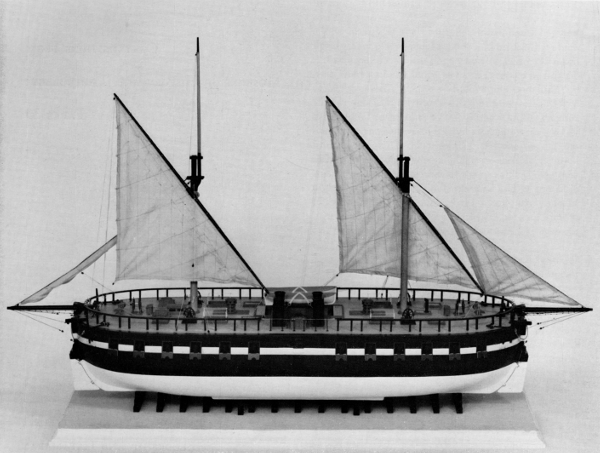 Figure 1.—Scale model of Fulton's Steam Battery in the Museum of History and Technology. (Smithsonian photo P-63390-F.)
Howard I. Chapelle
Robert Fulton’s “Steam Battery,” a catamaran-type blockship, was built during the War of 1812. Until recently, not enough material has been available to permit a reasonably accurate reconstruction of what is generally acknowledged to be the first steam man-of-war.
With the discovery, in the Danish Royal Archives at Copenhagen, of plans of this vessel, it is now possible to prepare a reconstruction and to build a model.
This article summarizes the history of the vessel, describes the plans and the reconstruction, and also evaluates its design with particular attention to the double-hull construction.
The Author: Howard I. Chapelle is curator of transportation in the Smithsonian Institution’s Museum of History and Technology.
The identity of the first steam man-of-war has been known for many years, and a great deal has been written and published on the history of this American vessel. Until recently, the only available drawing of the ship has been a patent drawing made for Robert Fulton. This does not comply with contemporary descriptions of the steamer and the drawing or plan is out of proportion with the known dimensions. The lack of plans has heretofore made it impossible to illustrate the vessel with any degree of precision, or to build a scale model.
The discovery in 1960 of some of the plans of this historic ship in the Danish Royal Archives at Copenhagen now makes possible a reasonably accurate reconstruction of the vessel and also clarifies some of the incomplete and often confusing descriptions by contemporary writers.
Of the numerous published accounts of the ship that are available, the most complete is David B. Tyler’s “Fulton’s Steam Frigate.”[1] A contemporary description of the vessel by the British Minister to Washington, 1820-23, Stratford Canning, was published by Arthur J. May.[2] In Naval and Mail Steamers of the United States, by Charles B. Stuart,[3] and The Steam Navy of the United States, by Frank M. Bennett,[4] the history of the ship and some descriptive facts are given. Stuart, in an appendix, gives in full the report of the Supervisory Committee (set up to administer the building contract). Tyler and Stuart, and the Committee Report are the principal sources from which the following summary of the ship’s history is drawn.
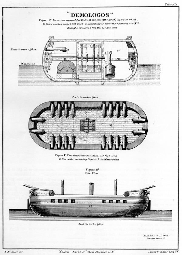
Figure 2.—“Demologos,” a wood engraving based on the sketch which Robert Fulton showed to President Madison in 1813. This wood engraving appears as plate 1 in Charles B. Stuart’s Naval and Mail Steamers of the United States, and illustrates the section on Naval Steamers, from which the account “The Demologos; or, Fulton the First,” is here reproduced (pp. 167-171). Stuart obtained the sketch, assumed to have been made for Fulton’s patent on the design of the Steam Battery, from the files of the U.S. Navy Department.
On December 24, 1813, Robert Fulton invited a group of friends—prominent merchants, professional men and naval officers—to his home in New York City and there presented a proposal for a project of great local interest. At that time the War of 1812 was in its second year and the economic effect of the British naval blockade was being felt severely. The blockade cut off seaborne trade and posed a constant threat of attack upon New York and other important ports, particularly Baltimore. To defend the ports, it had been proposed to build mobile floating batteries or heavily built and armed hulks with small sailing rigs, but the high cost of these and their doubtful value in helping to break the blockade, compared to the value and action of a very heavy, large frigate, or a 74-gun ship, caused authorities to hesitate to proceed with the construction of any blockships or floating batteries.
Fulton’s proposal concerned a floating battery propelled by steam power. He believed that steam propulsion not only would give it effective maneuverability with no loss of gunpower, but also would allow a successful attack upon the Royal Navy blockading ships during periods of protracted calm, when sailing men-of-war were nearly helpless. The blockaders then could be attacked and picked off, one by one, by the heavily armed steamboat.
Among those present at the meeting was Major General Henry Dearborn, a leading citizen and soldier who was later to become noted in American political history. The first step taken during this meeting was the founding of the Coast and Harbor Defense Company with Dearborn as president, Fulton as engineer, and Thomas Morris as secretary. Next, a committee was established to raise funds from Federal, State, and New York City governments as well as from individual contributors to build the battery. The members of this committee consisted of General Dearborn, Commodore Stephen Decatur, U.S.N.; General Morgan Lewis; Commodore Jacob Jones; U.S.N.; Noah Brown, shipbuilder; Samuel L. Mitchill; Henry Rutgers; and Thomas Morris.
The committee proved cumbersome and was reduced to General Lewis, Issac Bronson, Henry Rutgers, Nathan Sanford, Thomas Morris, Oliver Wolcott, and John Jacob Astor. Known as the Coast Defense Society and with the name of Pyremon given the ship in prospectus, they attempted, unsuccessfully, to raise funds privately.
The estimated sums to build a battery 130 feet long, with a 50-foot beam, capable of a speed of 5 mph, and carrying 24 long guns (18-pdr.), was $110,000. Fulton, still the chief engineer, in an effort to interest the Federal Government, built a model of the proposed vessel and submitted it to some prominent naval officers—Commodore Stephen Decatur, Jacob Jones, James Biddle, Samuel Evans, Oliver Perry, Samuel Warrington, and Jacob Lewis. All gave their support to the Society in a written statement and this recommendation proved helpful to the project in Congress and in the Navy Department. In the process of passing a bill which went to the Senate Naval Affairs Committee calling for $250,000 for the construction of the floating battery, the sum was raised to $1,500,000 for the construction of “one or more” floating batteries and passed on March 9, 1814.
To supervise the start of construction, the Coast Defense Society appointed a committee consisting of Dearborn, Wolcott, Morris, Mitchill, and Rutgers, with Fulton as engineer, and a model and drawing of the proposed vessel was submitted to the Patent Office. The Secretary of the Navy, although supporting the project, delayed action until he had weighed the importance of the batteries in relation to other war needs, for at this time the naval shipbuilding program on the Great Lakes was considered of prime importance. He also raised some technical questions concerning the design of the batteries, which Fulton answered with a description of the vessel as 138 feet on deck, 120 feet on the keel, 55 feet beam (each hull to have a 20-foot beam and the “race” between to be 15 feet wide), draft 8 or 9 feet loaded, and the intended speed was to be 4-1/2 to 5 mph. The ship was to carry 24 long guns (32-pdr.), the engine was to be 130 hp, and the total cost, $200,000. In his letters to the Secretary of the Navy, Fulton stated that Adam and Noah Brown would build the hull for $69,800 and that he would build [Pg 142]the engine, machinery and boilers for $78,000, a total of $147,800. He intended to have the boilers, valves, fastenings, and air pumps of brass or copper, which would raise the machinery costs 59 percent above that of stationary engines and boilers then in use.
On May 23, 1814, the Secretary of the Navy authorized the Coast Defense Society and its committee to act as Navy agents and to enter into the contracts required to build a vessel, and to draw on the Navy storekeepers or Navy Yard commandants for such stores or articles on hand needed for construction. The contracts were prepared and the committee now was officially empowered to act for the Society, with Rutgers, Wolcott, Morris, Dearborn, Mitchill, and Fulton. On June 4, Dearborn asked the Navy Department for $25,000 advance, for work had started. On the 6th, he informed the Secretary that he had been ordered to assume command of the defenses of Boston and that Rutgers had been appointed chairman of the construction committee in his place.
It is apparent that the Navy Department was pressed for funds, due to the very extensive shipbuilding programs on Lakes Erie, Ontario, and Champlain in addition to the seagoing vessels being built in some of the coastal ports. This was certainly one cause for the Secretary of the Navy’s reluctance to carry out the requirements of the bill passed by Congress immediately after its signature and, also, this reluctance caused the supervisory committee much embarrassment in its administration of the contract.
Another factor which caused difficulty in the administration of the contract was the position of Adam and Noah Brown. The brothers were deeply involved in the shipbuilding program on the Lakes, in which they were associated at times with Henry Eckford. The Browns constructed a blockhouse, shops, and quarters at Erie; in addition to Perry’s two brigs and five of his schooners, they also built some of the Lake Ontario vessels and, later, the Saratoga on Lake Champlain. In their New York yard, whose operation continued throughout the war, they built some large letter-of-marques: the General Armstrong, Prince de Neufchatel, Zebra, Paul Jones, and some smaller vessels. They also cut down the 2-decked, merchant ship China into a single flush-deck letter-of-marque, renamed Yorktown; and they had a contract to build the sloop-of-war Peacock. It is remarkable that the Browns could undertake and complete so much work between 1813 and 1815 and still be able to build the steam battery in a very short time.
With the contracts in order, the Browns began building. The keels of the battery were laid June 20, 1814. It is apparent that the Browns prepared the original hull plans, undoubtedly before the building authority was obtained. The vessel required only about four months to build; she was launched October 29, 1814, at 9 a.m. This was an excellent performance, considering the size of the vessel, the amount of timber required and handled in her massive construction, and the other work being done by the builders. During the ship’s construction, sightseers were a nuisance and finally guards had to be obtained. During the building of the steam battery, work had to be practically stopped on the sloop-of-war Peacock at one period after she had been partially planked.
There were difficulties in obtaining metalwork for the vessel during her construction, due to the blockade and the demand for such material for other shipbuilding at New York. On November 21, 1814, the ship was towed from the Browns’ yard on the East River by Fulton’s Car of Neptune and Fulton, each lashed to the sides of the battery, and taken to Fulton’s works on the North River. There Fulton supervised in person the completion of the vessel and construction of her machinery. Undoubtedly only a little of his time was required in inspection of the Browns’ work on the battery, for the shipbuilders had been closely associated with Fulton throughout the life of the project and were fully capable as ship designers. The work on the machinery was another matter, however, for men capable of working metal were scarce and few workmen could read plans. Fulton had some of the work done outside of his own plant, particularly the brass and copper work (mostly by John Youle’s foundry). As a result, Fulton was required to move from plant to plant, keeping each job under almost constant observation and personally supervising the workmen. The equipment then available for building a large engine was inadequate in many ways. The large steam cylinder presented a problem: it had to be recast several times and some of the other parts gave trouble, either in casting or in machining and fitting.
[Pg 143]
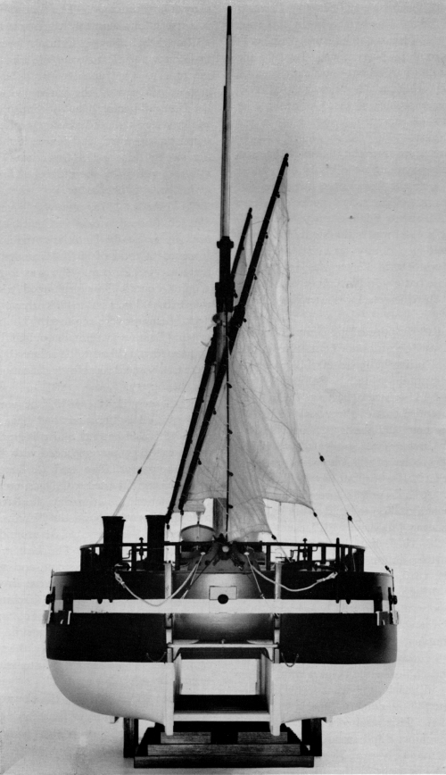
Figure 3.—Scale model of Steam Battery, showing double
hull, in the Museum of History and Technology. (Smithsonian photo
P-63390-D.)
Guns for the battery were another problem. Only 3 long guns (32-pdr.), were available at the Navy Yard. The Secretary of the Navy promised some captured guns then at Philadelphia. Because of the blockade, these had to come overland to New York. The captured guns thus obtained were probably English, [Pg 144]part of the cargo of the British ship John of Lancaster captured by the frigate President early in the war. Apparently 24 guns were obtained this way; only 2 were obtained from the Navy Yard. In July the Supervising Committee carried out some experimental damage studies, in which a 32-pdr. was fired at a target representing a section of the topsides of the battery. Drawings of the result were sent to the Secretary of the Navy.
Further problems arose over the delays of the government in making payments: the banks discounted the Treasury notes, so the Committee members had to advance $5,000 out of their own pockets. There was fear that British agents might damage the vessel, and although the project was undoubtedly known to the British, no evidence of any act of sabotage was ever found. Captain David Porter was assigned to the command of the battery in November, and it was upon his request that the vessel was later rigged with sails.
With the Steam Battery approaching completion, the Secretary of the Navy became more enthusiastic and the construction of other batteries of this type was again proposed. Captain Stiles, a Baltimore merchant, offered to build a steam battery, the hull to cost $50,000; the entire cost of the vessel, $150,000, was raised in Baltimore and the frames of a battery erected. Another battery was projected at Philadelphia and the Secretary of the Navy wanted one or more built at Sackett’s Harbor, but naval officers and Fulton objected. A bill put before Congress to authorize another half million to build steam batteries passed the first reading January 9, 1815, went to the House February 22, 1815, but the end of the war prevented any further action on it.
On February 24, 1815, Fulton died. He had been to Trenton, New Jersey, to attend a hearing on the steamboat monopoly and, on the way back, the ferry on North River was caught in the ice. Fulton and his lawyer, Emmet, had to walk over the ice to get ashore. On the way, Emmet fell through and Fulton got wet and chilled while helping him. After two or three days in bed Fulton went to his foundry to inspect the battery’s machinery causing a relapse from which he died. This resulted in some delay in completing the machinery and stopped work on the Mute, an 80-foot, manually propelled, torpedo boat that Fulton was having built in the Browns’ yard.
It was decided to suspend work on the Baltimore battery after an expenditure of $61,500, but the New York battery was to be completed to prove the project was practical. The final payment of $50,000 was made four months after it was requested.
Charles Stoudinger, Fulton’s foreman or superintendent, was able to complete and install the ship’s machinery. On June 10, 1815, the vessel was given a short trial run in the harbor with Stoudinger and the Navy inspector, Captain Smith, on board. This trial revealed the need of some mechanical alterations; sails were not used, and it was found she could stem the strong tide and a fresh headwind. The vessel also was visited by the officers of French men-of-war at anchor in the harbor.
On July 4, 1815, she was given another trial. She left Fulton’s works at Corlear’s Hook at 9 a.m., ran out to Sandy Hook Lighthouse, bore west and returned, a total of 53 miles under steam, reaching her slip at 5:20 p.m. She was found to steer “like a pilot boat.” This prolonged trial revealed that the stokehold was not sufficiently ventilated and more deck openings were required. The windsails used in existing hatches were inadequate. The paddle wheel was too low and had to be raised 18 inches, and there were still some desirable modifications to be made in the machinery.
On September 11, 1815, she was again given a trial run. All alterations had been made, including the addition of hatches and raising the paddle wheel, and her battery was on board with all stores, supplies, and equipment. She had 26 long guns (32-pdr.), mounted on pivoted carriages, and now drew 10 feet 4 inches. On this day she left her slip at 8:38 a.m. and went through the Narrows into the Lower Bay, where she maneuvered around the new frigate Java at anchor there. The battery then was given a thorough trial under steam and sail and, with the ship underway, her guns were fired to see if concussion would damage the machinery. The vessel was found to be a practical one, capable of meeting the government’s requirements in all respects; her speed was 5-1/2 knots. However, the stokehold temperature had reached 116° Fahrenheit! She returned to her slip at 7:00 p.m.
On December 28, 1815, the Committee in a written report to the Secretary of the Navy,[5] gave a description of the vessel and praised her performance. At this time a set of plans was made by “Mr. Morgan,” [Pg 145]of whom no other reference has appeared, and sent to the Navy Department. These cannot now be found. The Committee recommended the battery be commissioned and used for training purposes. This suggestion was not followed.
The ship remained in her slip during the winter, and in June 1816 she was turned over to the Navy and delivered to Captain Samuel Evans, commandant of the New York Navy Yard. Captain Joseph Bainbridge was assigned to her command. However, she was not commissioned and soon after her delivery she was housed over and placed “in ordinary,” that is, laid up. The final settlement showed that the Committee, as Navy agents, had paid out $286,162.12 with $872.00 unpaid, as well as a claim for $3,364.00 by Adam and Noah Brown, making a total of $290,398.12.
The following year, on June 18, 1817, she was unroofed and put into service with a small crew. With President James Monroe on board, she left the Navy Yard about noon for a short trip to the Narrows and then to Staten Island and returned in the evening. The next day she was again placed “in ordinary.”
Four years later, in 1821, when her guns and machinery were removed, it was found that she was rapidly becoming rotten. She was then utilized as a receiving ship. At 2:30 p.m. on June 4, 1829, she blew up, killing 24 men and 1 woman, with 19 persons listed as injured. Among those killed was one officer, Lt. S. M. Brackenridge. Two lieutenants and a Sailing Master were hurt, four midshipmen were severely injured, and five persons were listed as missing. The explosion of 2-1/2 barrels of condemned gunpowder was sufficient, due to her rotten condition, to destroy the ship completely. A Court of Inquiry blamed a 60-year-old gunner, who supposedly entered a magazine with a candle to get powder for the evening gun. It was stated to the court that about 300 pounds of powder in casks and in cartridges was on board the ship at the time.[3a]
She was not replaced until the coast-defense steamer Fulton was built in 1837-38, though in 1822 the Navy purchased for $16,000 a “steam galliot” of 100 tons, the Sea Gull, to be used as a dispatch boat for the West Indian squadron engaged in suppressing piracy during 1823. In 1825 she was laid up at Philadelphia, and in 1840 she was sold for $4,750.
It is a curious fact that the battery did not receive an official name, as did the sailing blockship on the ways at New Orleans, which at the end of the War of 1812 was officially listed as the Tchifonta. Nor was the battery given a number, as were the gunboats. In official correspondence and lists, the steam battery is referred to as the “Fulton Steam Frigate,” or as the “Steam Battery,” but in later years she was referred to as the “Fulton” or “Fulton the First.” Perhaps the explanation is that as she was the only one of her kind she was not numbered, and as she was not considered fit for coastal or extended ocean voyages, she was not given a name.
The designs of American blockships that have survived are those of the Tchifonta,[6] 145 feet long, 43-foot moulded beam, 8-foot 6-inch depth in hold, and about 152 feet 9 inches on deck. She was to carry a battery of 22 long guns (32-pdr.), on the main deck 12 carronades (42-pdr.), on forecastle and quarter decks. She was to have been rigged to rather lofty and very square topgallant sails, and would have been capable of sailing fairly well, though of rather shoal draft, drawing only about 8 feet 6 inches when ready for service. She was sold on the stocks at the end of the war and her later history is not known.
Another and earlier design for a blockship, or floating battery, was prepared by Christian Bergh for Captain Charles Stewart in 1806. This was a sailing vessel for the defense of the port of New York, planned to mount 40 guns (32-pdr.), on her two lower decks and 14 carronades (42-pdr.), on her spar deck. She was to be 103 feet 6 inches between perpendiculars, a 44-foot moulded beam, 10-foot depth of hold, and drawing about 9 feet when ready for service. She was intended to be ship-rigged, but was never built.[7] A few small sloop-rigged block vessels also were built during Jefferson’s administration. The sloop-of-war Saratoga, built on Lake Champlain by the Browns, in 1813, was practically a blockship. A plan for a proposed “Guard Ship,” or “Floating Battery,” was made by James Marsh at Charleston, South Carolina, in 1814. This was an unrigged battery, 200 feet extreme length, 50-foot moulded beam, 9-foot depth of hold, to mount 32 guns (42-pdr.), on a flush deck, with a covering deck above.[8]
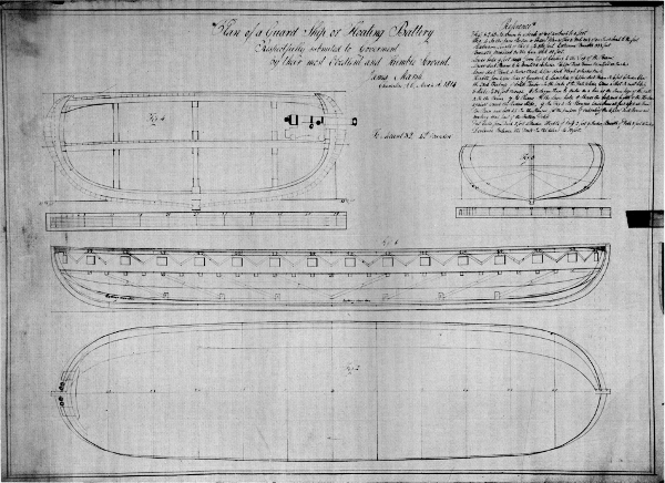
Figure 4.—Design for an unrigged floating battery proposed by James Marsh, Charleston, South Carolina, March 14, 1814.
[Pg 147]Through the courtesy of the trustees of the National Maritime Museum, Greenwich, England, the Rigsarkivet, Copenhagen, Denmark, and the Statens Sjöhistoriska Museum, Stockholm, Sweden, the author has been able to illustrate in this article the designs of some of the early floating batteries.
In the last quarter of the 18th century and later, the Danes had built sail-propelled floating batteries or blockships, which were employed in the defense of Copenhagen. The British built at least one sail-propelled battery, the Spanker, in 1794. This was a scow of very angular form with overhanging gun-deck, bomb-ketch-rigged, and about 120 feet overall 42-foot 4 inches moulded beam and 8-foot depth of hold. She is said to have been a failure due to her unseaworthy proportions and form; the overhanging gun deck and sides were objected to in particular. She is called a “Stationary Battery” in her plans, which are in the Admiralty Collection of Draughts, National Maritime Museum, Greenwich.
The contemporary descriptions of the Fulton Steam Battery do not agree. This was in part due to differences between the dimensions given out by Fulton during the negotiations with the Federal Government, and after the ship’s construction was authorized. From the context of various statements concerning the projected vessel, such as that of the naval officers, the changes in the intended dimensions of the ship can be seen. For example, the officers state the model and plan shown them would produce a battery carrying 24 guns (24- and 32-pdrs.), and a letter from Fulton to Jones,[9] shows she was to be 138 feet on deck and 55-foot beam. The final reported dimensions, given by the Supervisory Committee,[10] are 156 feet length, 56 feet beam, and 20 feet depth.
In addition there are a few foreign accounts which give dimensions and descriptions. The most complete was probably that of Jean Baptiste Marestier, a French naval constructor who visited the United States soon after the end of the War of 1812 and published a report on American steamboats in 1824.[11] The Steam Battery is barely mentioned though a drawing of one of her boilers is given. Marestier made another report on the American Navy, however. Extensive searches have been made for this in Paris over the last 14 years, but this paper has not been found in any of the French archives. References to the original text indicate that the naval report dealt very extensively with the Steam Battery. Some of his comments on the battery appeared in Procès-verbaux des Séances de l’Académie des Sciences.[12] Marestier considered the powers of the battery to have been overrated due to fanciful accounts of some laymen writers. He was aware of the shortcomings of the double hull in a steam vessel at the then-possible speeds, but he apparently thought two engines, one in each hull and each with its boilers would be better than Fulton’s arrangement of boilers in one hull and engine in the other. He noted that the paddle wheel turned 16-18 rpm and that steam pressure sustained a column of mercury 25 to 35 centimeters. The safety valve was set at 50 centimeters. Fuel consumption was 3-5/8 cords of pine wood per hour.
In view of the access Marestier is known to have had to American naval constructors, shipbuilders, and engineers, it is highly probable that he not only obtained the building plan of the ship but also some of the earlier project plans from the builders and from Fulton’s superintendent, Stoudinger. It is, therefore, a great misfortune that his lengthy report on the Battery cannot be produced.
A French naval officer who investigated the ship, M. Montgéry, also wrote a description, published in “Notice sur la Vie et les Travaux de Robert Fulton.”[13]
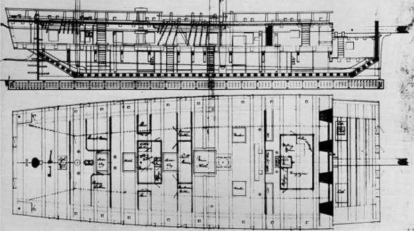
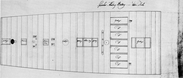
Figure 5.—Floating battery Spanker built, in England by William Barnard, at Deptford on the Thames, and launched June 14, 1794. Rigged as a bomb ketch, its length is 111 feet 7 inches in the keel, extreme beam 42 feet 4 inches, depth of hold 8 feet. Upper deck plan also shown.
It should be noted in regard to what Montgéry wrote about the Battery, that in 1821 it had been considered desirable to disarm the ship. The engineer in charge, William Purcell, had reported that as there were not proper scuppers, dirt and water had entered the hull and had collected under the engine and boilers, causing damage to the hull, and also that with guns removed, the Battery would float too high for the paddle wheel to propel the vessel; so it had [Pg 149]been decided to remove all machinery as well as the armament.
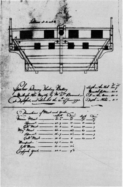 Figure 5.
Montgéry’s description, published in 1822, was taken from his report to the Minister of Marine and Colonies. It noted the battery was made of two hulls separated by a channel, or “race,” 15-1/2 feet wide, running the full length of the vessel. The two hulls were joined by a deck just above the waterline, as well as by an upper deck, and also connected at their keels by means of 12 oak beams each 1 foot square. The vessel was 152 feet long, 57 feet beam, and 20 feet deep. Sides were 4 feet 10 inches thick, and the ends of the hull were rounded and alike. There were two rudders at each end, one on each hull, alongside the race. The eight paddle blades, each 14-1/2 feet by 3 feet, turned in either direction by stopping the engine piston at half-stroke and reversing the flow of steam. Rigged with two lateen sails and two jibs, the ship sailed either end first. The engine of 120 hp was in one hull and two boilers were in the other. Other sources, Marestier, and Colden in Procès-verbaux des Séances de l’Académie des Sciences,[14] gave additional information (some of it incorrect): the engine was inclined, with a 4-foot-diameter cylinder, 5-foot stroke, direct-connected to the paddle wheel, which was turned at 18 rpm. The boilers were 8 × 22 feet with the fireboxes in inside cylinders, each about 5 feet in diameter, and extending about half the length of the boiler from the fire doors. Two fire tubes, each about 3 feet in diameter, returned the gases from the inside end of the fireboxes to the stacks at the firing end. Except at the fire-door end, the firebox was completely surrounded by water. The boiler pressure of about 6 psi was not maintained, varying somewhat with each stroke of the engine.
Water level in the boilers was indicated by try cocks. The safety valve was controlled by a counterbalanced lever. A jet of salt water was injected into the exhaust trunk to form a vacuum by condensation. An air pump transferred condensate and sea water into a tank from which it passed overboard. Only about a tenth of this water was returned to the boilers.
Montgéry stated also that only the lower or gun deck was to be armed. No bulwarks were on the spar deck, only iron stanchions to which were fastened a breastwork of wet cotton bales when the Steam Battery was in action.
The Battery was designed to carry 30 guns (32-pdr.), with 3 guns in each end and 12 on each side, but no guns in the wake of paddle wheel and machinery. Hatches to give air to the stokehold were located amidships. The Battery was to have been supplemented at the ends of each hull by a Columbiad “submarine gun” (100-pdr.), Fulton’s invention, but these were not fitted. Provision was to be made in the fireboxes for heating shot, and a force pump with a cylinder 33 inches in diameter was employed to throw a stream of cold water, about 60-80 gallons per minute, for a distance of about two hundred feet. This could be done only when the paddle wheel was not in operation. The paddle wheel was housed, the top fitted with stairs to the spar deck. The gun deck, over the race, was used in part for staterooms, of which the bulkheads were permanent. Hammocks for the complement of 500 men were to be slung on the rest of the gun deck. The ship drew 10 feet 4 inches, with the port sills about 5-1/2 feet above the loadline. Burning wood, the vessel could carry about 4 days’ supply of fuel; burning coal, she carried 12 days’ supply.
Montgéry said that the vessel would be vulnerable to bombshells and hot shot, and that furthermore she could be boarded. The displacement of the ship, at service draft, was 1,450 tons, a figure Montgéry [Pg 150]obtained from a copy of the original plan given him by Noah Brown.
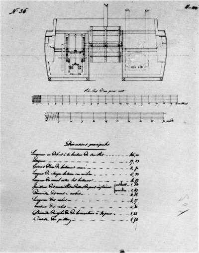
Figure 6.—French sketch, in Rigsarkivet, Copenhagen, of inboard profile and arrangement of Fulton’s Steam Battery, showing details of the Fulton engine, probably taken from one of his preliminary designs.
In 1935, Lieutenant Ralph R. Gurley, USN, attempted a reconstruction in sketches of the vessel published in his article “The U.S.S. Fulton the First” in the U.S. Naval Institute Proceedings.[15] This reconstruction was based on the Patent Office drawing prepared for Fulton, and published by Stuart and Bennett, and the foregoing French sources. The Patent Office drawing showed the engine was an inclined cylinder and Lt. Gurley shows this in his sketch; in his text (p. 323) he says, “The engine was an inclined, single-cylinder affair with a 4-foot base and a 5-foot stroke.” Gurley’s attempt to reconstruct the Steam Battery is the only one known to the author.
In 1960, Kjeld Rasmussen, naval architect of the Danish Greenland Company, was requested by the author to inspect in the Danish Royal Archives at Copenhagen a folio of American ship plans, the index of which had listed some Civil War river monitors. Mr. Rasmussen found the monitor plans had been withdrawn but discovered that three plans of Fulton’s Steam Battery existed, as well as plans of the first Princeton, a screw sloop-of-war.
Copies of the Steam Battery’s plans were obtained at Copenhagen in September 1960 through the courtesy of the archivist, and were found to consist of the lines, copied in 1817, an inboard profile and arrangement, and a sail and rigging plan. From these the reconstruction for a scale model was drawn and is presented here with reproductions of the original drawings upon which the reconstruction is based.
It is apparent that Montgéry’s description is generally accurate. The vessel is a catamaran, made of two hulls, double-ended and exactly alike. The outboard sides are “moulded,” with round bilges, the inboard sides are straight and flat, as though a [Pg 151]hull had been split along the middle line and then planked up flat where split. The hulls are separated by the race, in which the paddle wheel is placed at mid-length. The topsides are made elliptical at the ends, and the midsection shows a marked tumble-home over the thick topside planking but less on the moulded lines.
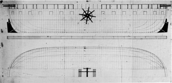 Figure 6.
The lines plan agreed rather closely to Montgéry’s description of the hull. After careful fairing it was found the lines drawing would produce a vessel 153 feet 2 inches overall outside the stems, or about 151 feet over the planked rabbets, with a moulded beam of 56 feet and extreme beam of 58 feet. The moulded depth was 22 feet 9 inches and the width of the race was 14 feet 10 inches, plank to plank. The room and space of framing shown was 2 feet. The designed draft appears to be 13 feet and this would bring the port sills 5 feet 6 inches above the loadline and the underside of the gun-deck beams about 2 feet 9 inches above the loadline.
The lines plan is a Danish copy, probably of the building plan by Noah Brown, and may be based on the plan Montgéry obtained from Brown. The spar deck has the iron stanchions (Gurley translated these as “chandeliers”) which are set inboard 4 feet from the plank-sheer. This gives room for cotton bales, outboard the stanchions, to form a barricade. As will be seen by comparing the original Danish drawing with the model drawing, the construction indicates that the iron stanchions should be carried around the ends of the hull in the same manner as along the sides, since the lower ends of the iron stanchions pass through the spar deck and are secured to the inside of the inner ceiling of the gun deck. The rudders are as shown in the Danish drawing, and it is supposed that they were operated ferryboat fashion, one at each end of the vessel. Hence, each pair of rudders was toggled together by a cross-yoke. This was probably operated by a tiller (possibly the cross-yokes and tillers were of iron) pivoted under the beams of the gun deck [Pg 152]close to the ends of the ship. Tiller ropes led from a tackle under the gun-deck through trunks to the spar deck, where the wheels were placed. This allowed proper sweep to the tillers and operation of each pair of rudders. The paddle wheel was apparently of iron, with wooden blades, and agrees with Montgéry’s description. In the plan for the model it is shown raised 18 inches above the original design position, to agree with trial requirements.
It should be observed that the close CL-to-CL frame spacing created a hull having frames touching one another, at least to above the turn of the bilge, so the vessel was almost solid timber, before being planked and ceiled, from keel to about the loadline. The sides are not only heavily planked but, after the frames were ceiled with extraordinarily heavy, square timbering, a supplementary solid, vertical framing was introduced inboard and another ceiling added. The sides scale about 5 feet from outside the plank to the inboard face of the inner ceiling at the level of the gunports.
The hulls were tied together athwartship by the deck beams of the gun deck and spar deck, except in the wake of the paddle wheel. Knees were placed along the sides of the race at alternate gun-deck beams. In addition, the 12 1-foot-square timbers, crossing the race at the rabbets of the hulls, (mentioned by Montgéry) are shown. These must have created extraordinary resistance, even at the low speed of this steamer. The deck details shown are the results of reconstruction of the inboard works.

Figure 7.—Original lines of Robert Fulton’s Steam Battery, a Danish copy dated September 12, 1817; found in Rigsarkivet, Copenhagen.
The use of catamaran hulls, or “double-hulls,” has been periodically popular with ship designers since the time of Charles II of England. The earliest of such vessels known in the present day were four sloops or shallops designed 1673-1687 by Sir William Petty, who was an inventor in the field of naval architecture and received some attention from Charles II and from the Royal Society.
The first Petty experiment, the Simon & Jude, later called Invention I, was launched October 28, 1662. She was designed with two hulls cylindrical in cross section, each 2 feet in diameter, and 20 feet long. A platform connected the hulls, giving the boat a beam of a little over 9 feet. She had a 20-foot mast stepped on one of the crossbeams connecting the hulls, with a single gaff sail. In sailing trials she beat three fast boats: the King’s barge, a large pleasure boat, and a man-of-war’s boat. This [Pg 153]“double-bottom,” also called a “sluiceboat” or “cylinder,” was later lengthened at the stern to make her 30 feet overall.
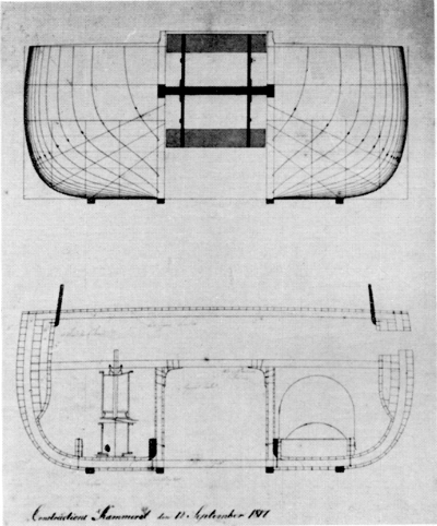 Figure 7.
The King did not support Petty, to the latter’s great disappointment, and Petty next built a larger double-bottom, Invention II. This catamaran was lapstrake construction. Not much is known of this boat except that she beat the regular Irish packet boat, running between Holyhead and Dublin, in a race each way, winning a £20 wager. She was launched in July 1663; what became of her was not recorded.
A third and still larger boat, the Experiment, launched December 22, 1664, appears to have been a large sloop. This vessel sailed by way of the Thames in April 1665 and went to Oporto, Portugal. She left Portugal October 20, 1665, for home, but apparently went down with all hands in a severe storm.
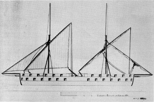
Figure 8.—Danish copy of original sail plan of Robert Fulton’s Steam Battery, dated September 12, 1817, in Rigsarkivet, Copenhagen.

Figure 9.—Lines of Fulton’s Steam Battery, as reconstructed for a model in the Museum of History and Technology.

Figure 10.—A reconstruction of inboard works of the Steam Battery, for construction of the model in the Museum of History and Technology.
For 18 years Petty did no more with the type, but finally, in July 1684, he laid down a still larger sloop [Pg 155]with two decks and a mast standing 55 feet above her upper deck. She was named St. Michael the Archangel and is probably the design in Pepys’ Book of Miscellaneous Illustrations in Magdalene College, Cambridge, England. This vessel proved unmanageable and was a complete failure.
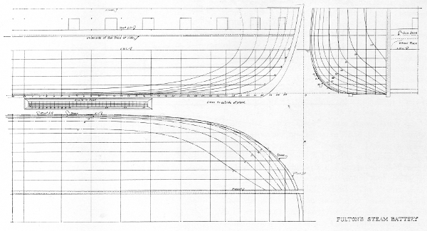
Figure 11.—Model lines redrawn to outside of plank to show hydrodynamic form of the Steam Battery.
Though the double canoes of the Pacific Islands were probably known to some in Europe in 1662, there is no evidence that Petty based his designs on such craft. He appears to have produced his designs spontaneously from independent observations and resulting theories. Before Petty concluded his experiments, a number of double-hull craft had been produced by others; however, some “double” craft, such as “double shallops” may have been “double-enders,” as shown by a “double-moses boat” of the 18th century and later.[16]
The use of two canoes, joined by a platform or by poles was common in colonial times; in Maryland and Virginia, dugouts so joined were used to transport tobacco down the tidal creeks to vessels’ loading. Such craft were also used as ferries. M. V. Brewington’s Chesapeake Bay Log Canoes[17] and Paul Wilstack’s Potomac Landings[18] illustrate canoes used in this manner. A catamaran galley, two round-bottom hulls, flat on the inboard side (a hull split along the centerline and the inboard faces planked up), 113 feet long and each hull a 7-foot moulded beam, 6-foot 6 inches moulded depth, and placed 13 feet apart, was proposed by Sir Sidney Smith, R.N., in the 1790’s, and built by the British Admiralty. Named Taurus, she is shown by the Admiralty draught to have been a double-ender, with cabins amidships on the platform, an iron rudder at each end (between the hulls) steered with tillers (to unship), and with a ramp at one end. The plans are undated, signed by Captain Sir Sidney Smith, and a field-carriage gun is shown at the ramp end of the boat. This, and the heavy rocker in the keels, suggests the Taurus was intended for a landing boat. No sailing rig is indicated, but tholes for 12 oars or sweeps on each side are shown. The oarsmen apparently sat on deck, or on low seats, with stretchers in hatches [Pg 156]between each pair of tholes (Admiralty Collection of Draughts, The National Maritime Museum, Greenwich, England).
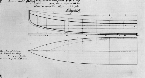
Figure 12.—General plan of the Taurus, a catamaran galley gunboat proposed by Sir Sidney Smith, R.N., to the British Admiralty in the early years of the French Revolution. From the Admiralty Collection of Draughts, National Maritime Museum, Greenwich.
Another experimenter with the double-hull type of vessel was a wealthy Scot named Patrick Miller who was particularly interested in manual propulsion of vessels, employing geared capstans to operate paddle wheels. In a letter dated June 9, 1790, Miller offered Gustav III of Sweden a design for a double-hulled 144-gun ship-of-the-line (rating as a 130-gun ship) propelled by manually operated capstans connected to a paddle wheel between the hulls. She was rigged to sail, with five masts and was to be 246 feet long, 63 feet beam, and 17 feet draft; the hulls were 16 feet apart.
This project was submitted by the King to Fredrik Henrik af Chapman, the great Swedish naval architect, who made an adverse report. Chapman pointed out in great detail that the weight of the armament, the necessary hull structure, the stores, crew, ammunition, spars, sails, rigging and gear, would greatly exceed Miller’s designed displacement. He also pointed out the prime fault of catamarans under sail—slow turning in stays. He suggested that the speed under sail would be disappointing. He doubted that a double-hull ship of such size could be built strong enough to stand a heavy sea. He remarked that English records showed that a small vessel of the catamaran type had been built between 1680 and 1700 which had sailed well (this may have been one of Petty’s boats), and that “36 years ago” he had seen 8 miles from London, a similar boat that had been newly built by Lord Baltimore and was about 50 feet long; this was a failure and was discarded after one trial. Therefore, said Chapman, the Miller project was not new but rather an old idea. Chapman’s final remark is perhaps the best illustration of his opinion of the catamaran, “Despite all this, two-hull vessels are completely sound when the theory can be properly applied; that is in vessels of very light weight, and of small size, with crews of one or two men.”
A “model” of such a double-hull ship—the Experiment, built at Leith, Scotland, in 1786 by J. [Pg 157]Laurie—was sent to Sweden by Miller. She was 105 feet long, 31 feet beam, and cost £3000. This vessel arrived in the summer of 1790 and King Gustav in a letter dated July 26 ordered Col. Michael Anckerswärd to welcome the vessel at Stockholm. The King presented Miller with a gold snuffbox and a painting was made of the vessel. The Experiment had five paddle wheels in tandem between her hulls, operated by geared capstans on deck. These gave her a speed of 5 knots but caused the crew to suffer from exhaustion in a short time. The vessel was badly strained in a storm and was finally abandoned at St. Petersburg, Russia.[19]
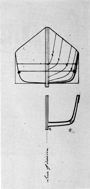 Figure 12.
Miller later turned to the idea of employing steam instead of manual power and built a 25-foot double-hulled pleasure boat of iron fitted with a steam engine built by William Symington. Also named Experiment, she was an apparent success, so Miller had a 60-foot boat built of the double-hull design and fitted with an engine built by Symington. She reached a speed of 7 mph on the Forth and Clyde Canal. However, Miller lost interest when he found that the Symington engine was unreliable and that Great Britain showed very little public support for such projects.
Fulton was acquainted with Symington’s work and probably had heard of Miller’s vessels. At any rate, he employed the double-hull principle in his steam ferryboats, the first of which was the Jersey, a 188-ton vessel built by Charles Browne, which began service July 2, 1812. The next year he had a sister ship built, the York. These vessels were based on his patent drawing of 1809. In 1814 he had another vessel of this type built, the Nassau. It was, therefore, logical that he should apply this design to the Steam Battery. The double-hull design had worked well in these ferries, and the design would give protection from shot to the paddle wheel. The Battery would have the ability to run forward or astern so as not to be exposed to a raking fire from the enemy while maneuvering in action. The application of this “ferryboat” principle to the Battery reduced the need for extreme maneuverability, the catamaran’s weakest point, even at low speed.
The resistance factors in the design are of relatively small importance, for the speed possible under steam in this period was very low. However, the plans show an apparently efficient hull form for the power available, aside from the drag of the beams across the race in the vicinity of the keel. The displacement was adequate. The height of the gun-deck above the water at the race made the Battery unsuitable for rough-water operation, but there is no evidence that Fulton or the sponsors of the vessel considered the Battery as a coastwise or seagoing steamer. However, the clearance of the gun deck above the water and the dip of the paddle wheel would have made the additional weight of an upper- or spar-deck battery prohibitive even had experience in action proven it desirable.
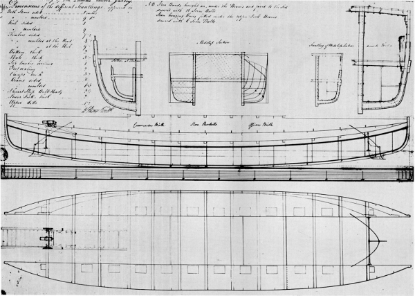
Figure 13.—Lines of Taurus. From the Admiralty Collection of Draughts, National Maritime Museum, Greenwich.
The sail and rigging plan is likewise a Danish copy and shows the two-masted lateen rig employed. The hull is shown with bulwarks and gunports on the spar deck but no other evidence that the Battery was finished in this manner has been found. The rig resembles that of some of Josiah Fox’s designs for Jeffersonian gunboats—double-enders designed to sail in either direction but without the jibs. The topmasts [Pg 159] do not appear to be more than signal poles and apparently were not fitted with sails; however, some European lateeners did have triangular topsails over a lateen and it is possible the Battery may have carried such sails. Considering the stability and displacement of the Battery, the rig is very small and not sufficiently effective. Shrouds were not required; the masts were supported by runners that were shifted when the yards were reversed, and in tacking. Apparently the jibstays also could be slacked off so that the lateen yards would not have to be dipped under them.
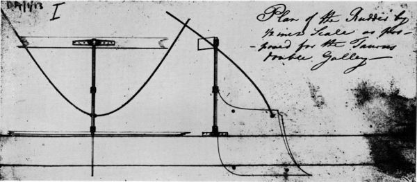
Figure 14.—Rudder detail of Taurus. From the Admiralty Collection of Draughts, National Maritime Museum, Greenwich.
The inboard profile is on tracing paper and the notes are in French. This drawing is of a simplified hull form having flat-bottom hulls with chines. It is possible that this is a tracing of a preliminary drawing obtained by Marestier or Montgéry, but no documentation can be found. Its importance is that it shows in some detail the engine and boilers, as well as the wheelbox, and another drawing of the paddle wheel, more or less duplicating the wheel shown in the Danish plan. No details of the deck arrangements are shown in any of the plans, except for the dome skylight over the fireroom in the boiler hull.
Both the lines plan and the inboard drawing show construction midsections and hull connections. These plans show that the engine was not inclined, but rather was vertical, contrary to Fulton’s patent drawing. The piston rod and the crosshead obviously passed through its gun deck in a large hatch. Also it is plain that there must have been large hatches afore and abaft the wheelbox to make the stepped wheelbox construction desirable. There also must have been a hatch in the gun deck under the domed skylight. It is improbable that the engine and skylight hatches were used for ladderways, passing scuttles, or companionways.
The boilers are shown in the inboard profile about as described and drawn by Marestier but with two stacks on each boiler, one to each flue; Marestier’s sketch in his report on American steamships shows the flues of each boiler trunked into a single stack. The battery had two boilers and the stacks are at the boilers’ fire-door end. The steam lines came off the crown of the boilers and probably passed through the ends of the wheelbox to the engine; a trunk for the steam lines would undoubtedly have been necessary.
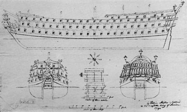
Figure 15.—Sketch of 130-gun ship proposed by Patrick Miller to King Gustav III of Sweden in 1790. In Statens Sjöhistoriska Museum, Stockholm.
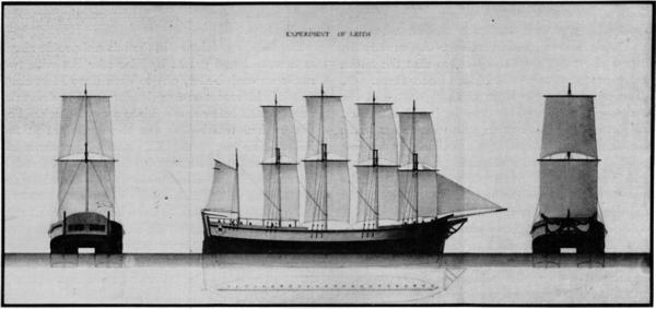
Figure 16.—Patrick Miller’s manually propelled (paddle-wheel) catamaran ship Experiment, built at Leith, Scotland, 1786. Scale drawing in Statens Sjöhistoriska Museum, Stockholm
The engine is shown to have had counterbalanced side levers, one on each side, and a single flywheel on the outboard side. The cylinder is over the condenser or “cistern,” connected by the steam line and valve box on the side. The cylinder crosshead is shown in the inboard profile to have reached the underside of the beams of the upper deck. The crosshead was connected by two connecting rods to the side levers. These levers operated the paddle wheel by connecting rods to cranks on the paddle-wheel shaft. There is [Pg 161]another pair of connecting rods from the side levers to the crosshead of the air pump. All connecting rods are on one arm of the side levers, the other end having only a counterbalance weight beyond the fulcrum bearing. The flywheel has a shaft fitted with two gears, and is driven through idler gears from gears on the paddle-wheel shaft; it turns at about twice the speed of the paddle wheel. No other pumps or fittings are shown in the engine hull, although manual pumps were probably fitted to fill and empty the boilers. Piping is not shown.
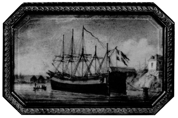
Figure 17.—Painting of the Experiment in the Statens Sjöhistoriska Museum, Stockholm.
The four rudders, toggled in pairs, are shown in both the lines and inboard drawings, but the shape is different in the two plans. Operation must have been by a tiller under the gun-deck beams. The outer end of the tiller may have been pivoted on the toggle bar and the inboard end fitted, as previously described, with steering cable or chain tackles. This seems to be the only practical interpretation of the evidence.
In the model it was necessary to reconstruct the deck arrangements without enough contemporary description. The outboard appearance and hull form, rig, and arrangement of armament require no reconstruction, for all that is of importance is shown in the lines and rig drawings, or in the inboard profile. The masts are shown to have been stepped over the race on the gun deck. The iron stanchions are shown in the lines drawing and in the construction section. However, their position at the ends of the Battery are apparently incorrectly shown in the original lines plan. The construction section shows these stanchions to have been stepped on the inside face of the inner ceiling and, as the ceiling structure was carried completely around the ship, the stanchions in the ends must have been placed inboard, as along the sides. The bowsprit was above deck and would probably be secured in the knighthead timbers at [Pg 162] the ends of the hull, as well as by the heel bitts shown in the Danish lines drawing. With the riding bitts shown inboard of the heel bitts at each end of the vessel, it is obvious that she would work her ground tackle at both ends and would therefore require two capstans; the wheelbox would prevent effective use of a single one. The capstans might be doubleheaded, as in some large frigates and ships-of-the-line.
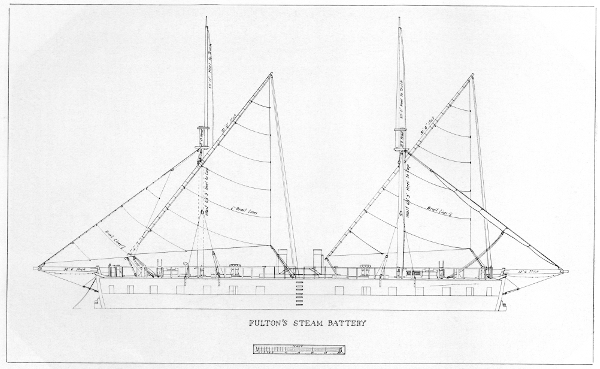
Figure 18.—Sail plan of Fulton’s Steam Battery as reconstructed for model in the Museum of History and Technology.
As to the remaining deck fixtures, hatches and fittings, these must be entirely a matter of speculation. Ladderways, passing scuttles, hatches, trunks, galley, heads and cabins were obviously required in a fighting ship and can only be located on the theory that, when completed, the Battery was a practical vessel.
It has been stated that the officers’ cabins were over the race; the logical place for the heads, galley, wardroom and mess also would be over the race, giving the remaining part of the gun deck for the necessary hatches, ladderways, trunks, etc., in the two hulls, space required for armament, and to sling the hammocks of a watch below. As the vessel was never fully manned, apparently, the space for hammocks is not a serious problem in a reconstruction. If the vessel had been manned as proposed by 500 men, hammocks for over 200 would have been required, which would give very crowded quarters in view of the limited space available.
Though no specific requirements were stated in the reports of the trials, it seems reasonable to suppose that additional hatches were cut in the decks to improve the fireroom ventilation. In the reconstruction drawings, these hatchways as well as the other deck openings and deck fittings—such as bilge pumps, companionways, skylights, binnacles, wheels and wheel-rope trunks, cable trunks, steampipe casings, and stack fiddleys—have been located in an effort to meet the imagined requirements of the working of a ship of this unusual form.
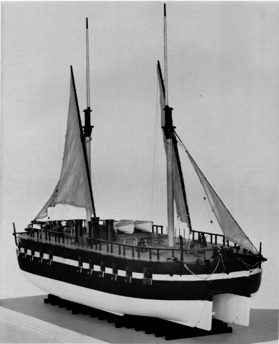
Figure 19.—Model of Steam Battery in the Museum of History and Technology. (Smithsonian photo 63990-E.)
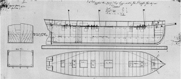
Figure 20.—Lines of steamer Congo, built in 1815-1816 for the British Admiralty and converted to a sailing survey vessel. From Admiralty Collection of Draughts, National Maritime Museum, Greenwich.
There are some unanswered questions that arose in the preparation of the reconstruction drawings. As has been shown, the original inboard arrangement plan found in Copenhagen shows four smokestacks, while Marestier’s sketch of the vessel’s boilers shows [Pg 165]trunked flues indicating that two stacks were used. It is possible that the boilers were first fitted so that four stacks were required; alterations made as a result of steaming trials may well have included the introduction of trunked flues and the final use of two stacks in line fore-and-aft. This would have required a rearrangement of the fiddley hatches amidships.
Another troublesome question was the doubtful arrangement of the four companionways on the spar deck. Perhaps only two were fitted, one on each side of the officers’ staterooms while the ladderways at the crew’s end of the ship were simple ladder hatches.
The decision to use four bilge pumps is based upon the lack of drag in the keel of the hulls, which would prevent accumulation of bilge water at one end of the hull. The use of four single-barrel pumps instead of four double-barrel pumps may be questioned, for chain pumps requiring two barrels would have been practical.
Allowance for stores was made by use of platforms in the hold. It is known from statements made to the Court of Inquiry, that the magazines were amidships and that a part of these was close to the boilers. Fuel and water would be in the lower hold under the platforms; hatches and ladderways are arranged to permit fueling the ship.
A few prints or drawings of the ship, aside from the patent drawing, have been found. There are two prints that show the launch of the vessel. One, a print of 1815, is in possession of the Mariners’ Museum, Newport News, Va., and is reproduced in Alexander Crosby Brown’s Twin Ships, Notes on the Chronological History of the Use of Multiple Hulled Vessels.[20] A poor copy of this print appears on page 13 of Bennett’s Steam Navy of the United States, and another and inaccurate sketch is shown on page 8. These pictures were of no use in the reconstruction as they show no details that are not in the Copenhagen plans. The patent drawing does not show deck details and in fact does not represent the vessel as built in any respect other than in being a catamaran with paddle wheel amidships between the hulls.
The Steam Battery did not have any particular influence on the design of men-of-war that followed her. In the first place, steampower was not viewed with favor by naval officers generally. This was without doubt due to prejudice, but engines in 1820-30 were still unreliable when required to run for long periods, as experienced by the early ocean-going steamers. The great weight of the early steam engines and their size in relation to power were important, and also important were practical objections that prevented the design of efficient naval ocean steamers until about 1840; even then, the paddle wheels made them very vulnerable in action. Until the introduction of the screw propellor it was not possible to design a really effective ocean-going naval steamer; hence until about 1840-45, sail remained predominant in naval vessels for ocean service, and steamers were accepted only in coast defense and towing services, or as dispatch vessels.
No immediate use of the double hull in naval vessels of the maritime powers resulted from the construction of the Steam Battery. The flat-bottom chine-built design employed by Fulton in North River, Raritan, and other early steamboats was utilized in the design for a projected steamer by the British Admiralty in 1815-16. This vessel was about 76 feet overall, 16-foot beam, and 8-foot 10 inches depth in hold. Her design was for a flat-bottom, chine-built hull with no fore-and-aft camber in the bottom, a sharp entrance, and a square-tuck stern with slight overhang above the cross-seam. Her side frames were straight and vertical amidships, but curved as the bow and stern were approached. She was to be a side-paddle-wheel steamer, and her hull was diagonally braced; the wheel and engine were to be about amidships where she was dead flat for about 14 feet. However, the engine and boilers were not installed; the engine was utilized ashore for pumping, and the vessel was completed in the Deptford Yard as a sailing ship. Under the name Congo she was employed in the African coast survey. Her plan is in the Admiralty Collection of Draughts, at the National Maritime Museum, Greenwich, England.
The double hull continued to be employed in both steam and team ferryboats in the United States and in England and France. A few river and lake steamers were also built with this design of hull. Continued efforts to obtain fast sailing by use of the double hull produced a number of sailing catamarans; of these the Herreshoff catamarans of the 1870’s showed high speed when reaching in a fresh breeze.
Designs for double-hulled steamers appeared during the last half of the 19th century; in 1874 the Castalia, a large, double-hull, iron, cross-channel steamer, was built by the Thames Iron-works Company at [Pg 166] Blackwall, England. She was 290 feet long, and each hull had a beam of 17 feet. The paddle wheel was placed between the hulls and, ready for sea, she drew 6-1/2 feet. She ran the 22 miles between Dover and Calais in 1 hour and 50 minutes, a speed much slower than that of the paddle-wheel, cross-channel steamers having one hull. Another double-hull steamer was built for this service by Hawthorn, Leslie and Company, Newcastle-on-Tyne, Scotland, in 1877. First named Express, she was renamed Calais-Douvres when she went into service in May 1878. Her length was 302 feet, her extreme beam 62 feet, and each hull had a beam of 18 feet, 3 inches. She drew 6-foot 7-1/2 inches ready for sea and the paddle wheel was between the hulls. On her trials she made 14 knots and burned coal excessively. Sold to France in 1880, she was taken out of service in 1889. Though popular, she was not faster than the single-hull steamers in this service and had been a comparatively expensive vessel to build and operate.
The many attempts to produce a very fast double-hull steamer and large sailing vessels have led to disappointment for their designers and sponsors. In the history of naval architecture, since Petty’s time, there have been a number of periods when the new-old idea of the double hull has become popular. Craft of this type have been commonly well publicized but, on the whole, their basic designs have followed the same principles over and over again and have not produced the sought-for increase in speed and handiness.
In very recent years there has been a revival in interest in sailing double-hull boats that is enthusiastic as to very small craft and somewhat restrained as to large boats. A few projects are under development for double-hull craft, power and sail, of over 90-foot length, including an oceanographic research vessel. In general, however, the performance of double-hull boats has shown that Chapman’s estimate of the type was reasonably correct and that there are limitations, particularly in maneuverability in the double-hull craft that could have been found by reference to the history of past experiments with the type.
[1] The American Neptune (1946), vol. 6, pp. 253-274.
[2] The American Neptune (1944), vol. 4, pp. 327-329.
[4] Pittsburgh, 1896, pp. 8-16.
[5] See pages 172 through 176 for this report, which is reproduced from Charles B. Stuart, Naval and Mail Steamers of the United States (New York, 1853), app., pp. 155-159.
[6] National Archives, Navy Records Plans, 80-7-14; and Howard I. Chapelle, History of the American Sailing Navy (New York: W. W. Norton & Co., 1949), pp. 293-295.
[7] National Archives, Navy Records Plans, 80-7-9; and Chapelle, History of the American Sailing Navy, pp. 226, 228.
[8] National Archives, Navy Records Plans, 80-7-15.
[9] National Archives, Naval Records Collection, Miscellaneous Letters, 1819, II.
[10] See p. 169, reproduced from Charles B. Stuart, Naval and Mail Steamers of the United States (New York, 1853), p. 15.
[11] Jean Baptiste Marestier, Mémoire sur les bateaux à vapeur des États-Unis d’Amérique, avec un appendice sur diverses machines relatives à la Marine (Paris: L’imprimerie Royal, 1824).
[12] 1820-1823, vol. 7, p. 437.
[13] Annales de l’industrie nationale et étrangère, ou Mercure Technologique (Paris, 1822), pp. 760-762.
[14] January 27, 1823, vol. 7, pp. 436-438.
[15] January-March 1935, vol. 61, pp. 322-328.
[16] Howard I. Chapelle, American Small Sailing Craft (New York: W. W. Norton & Co., Inc., 1951), pp. 29, 31.
[17] Newport News, Va.: The Mariners’ Museum, 1937, p. 23.
[18] Indianapolis, Ind.: Bobbs Merrill, 1932, p. 291.
[19] Henry William Edward, The Double Bottom or Twin Hulled Ship of Sir William Petty (Oxford: The Roxburghe Club, 1931).
[20] Publication No. 5 (Newport News: The Mariners’ Museum, 1939), p. 22.
U.S. GOVERNMENT PRINTING OFFICE: 1964
For sale by the Superintendent of Documents, U.S. Government Printing Office
Washington, D.C. 20402—Price 70 cents
Anckerswärd, Col. Michael, 157
Astor, John Jacob, 141
Baltimore, Lord. See Calvert.
Bennett, Frank M., 139, 150, 165
Bergh, Christian, 145
Biddle, James, 141
Brackenridge, S. M., 145
Brewington, M. V., 155
Brown, Adam and Noah, 141, 142, 145
Brown, Alexander Crosby, 165
Browne, Charles, 157
Calvert, George, Lord Baltimore, 156
Canning, Stratford, 139
Chapman, Fredrik Henrik af, 156, 166
Charles II of England, 152, 153
Coast and Harbor Defense Company, 141
Coast Defense Society, 141, 142
Colden, C. D., 149
Danish Greenland Company, 150
Danish Royal Archives, 139, 150
Decatur, Stephen, 141
Deptford Yard (England), 165
Eckford, Henry, 142
Emmet, ——, 144
Fox, Josiah, 157
Fulton, Robert, 139, 141, 142, 144, 147, 149, 150, 157, 159, 165
Gurley, Ralph R. (USN), 150, 151
Gustav III of Sweden, 156, 157
Hawthorn, Leslie, and Company (Scotland), 166
Jefferson, Thomas, 145
Jones, Jacob, 141
Jones, William, 147
Laurie, J., 157
Lewis, Jacob, 141
Lewis, Morgan, 141
Marestier, Jean Baptiste, 147, 149, 159, 162
Mariners’ Museum, 165
Marsh, James, 145
May, Arthur J., 139
Monroe, James, 145
Morgan, "Mr.", 144
National Maritime Museum (England), 147, 156, 165
Pepys, Samuel, 155
Perry, Oliver, 141
Petty, Sir William, 152, 153, 155, 166
Porter, David, 144
Purcell, William, 147
Rasmussen, Kjeld, 150
Rigsarkivet (Denmark), 147
Royal Society of London, 152
Smith, —— (Captain, USN), 144
Smith, Sir Sidney (RN), 155
Statens Sjöhistoriska Museum (Sweden), 147
Stewart, Charles, 145
Stiles, George, 144
Stoudinger, Charles, 144
Symington, William, 157
Thames Iron-works Company (England), 165
Tyler, David B., 139
Warrington, Samuel, 141
Wilstack, Paul, 155
Youle, John, foundry, 142
Transcriber’s corrections:
P. 152: ‘the Simon & Jude, later’—was ‘the Simon & Jude, latter’.
P. 159: ‘Its importance is that it...’—was ‘Its importance is that is...’.
Index: ‘Emmet, ——, 144’—was ‘Emmett, ——, 144’.
End of the Project Gutenberg EBook of Fulton's "Steam Battery": Blockship
and Catamaran, by Howard I. Chapelle

*** END OF THIS PROJECT GUTENBERG EBOOK FULTON'S "STEAM BATTERY": ***

***** This file should be named 31179-h.htm or 31179-h.zip *****
This and all associated files of various formats will be found in:
        http://www.gutenberg.org/3/1/1/7/31179/

Produced by Colin Bell, Louise Pattison, Joseph Cooper and
the Online Distributed Proofreading Team at
http://www.pgdp.net


Updated editions will replace the previous one--the old editions
will be renamed.

Creating the works from public domain print editions means that no
one owns a United States copyright in these works, so the Foundation
(and you!) can copy and distribute it in the United States without
permission and without paying copyright royalties.  Special rules,
set forth in the General Terms of Use part of this license, apply to
copying and distributing Project Gutenberg-tm electronic works to
protect the PROJECT GUTENBERG-tm concept and trademark.  Project
Gutenberg is a registered trademark, and may not be used if you
charge for the eBooks, unless you receive specific permission.  If you
do not charge anything for copies of this eBook, complying with the
rules is very easy.  You may use this eBook for nearly any purpose
such as creation of derivative works, reports, performances and
research.  They may be modified and printed and given away--you may do
practically ANYTHING with public domain eBooks.  Redistribution is
subject to the trademark license, especially commercial
redistribution.


*** START: FULL LICENSE ***

THE FULL PROJECT GUTENBERG LICENSE
PLEASE READ THIS BEFORE YOU DISTRIBUTE OR USE THIS WORK

To protect the Project Gutenberg-tm mission of promoting the free
distribution of electronic works, by using or distributing this work
(or any other work associated in any way with the phrase "Project
Gutenberg"), you agree to comply with all the terms of the Full Project
Gutenberg-tm License (available with this file or online at
http://gutenberg.org/license).


Section 1.  General Terms of Use and Redistributing Project Gutenberg-tm
electronic works

1.A.  By reading or using any part of this Project Gutenberg-tm
electronic work, you indicate that you have read, understand, agree to
and accept all the terms of this license and intellectual property
(trademark/copyright) agreement.  If you do not agree to abide by all
the terms of this agreement, you must cease using and return or destroy
all copies of Project Gutenberg-tm electronic works in your possession.
If you paid a fee for obtaining a copy of or access to a Project
Gutenberg-tm electronic work and you do not agree to be bound by the
terms of this agreement, you may obtain a refund from the person or
entity to whom you paid the fee as set forth in paragraph 1.E.8.

1.B.  "Project Gutenberg" is a registered trademark.  It may only be
used on or associated in any way with an electronic work by people who
agree to be bound by the terms of this agreement.  There are a few
things that you can do with most Project Gutenberg-tm electronic works
even without complying with the full terms of this agreement.  See
paragraph 1.C below.  There are a lot of things you can do with Project
Gutenberg-tm electronic works if you follow the terms of this agreement
and help preserve free future access to Project Gutenberg-tm electronic
works.  See paragraph 1.E below.

1.C.  The Project Gutenberg Literary Archive Foundation ("the Foundation"
or PGLAF), owns a compilation copyright in the collection of Project
Gutenberg-tm electronic works.  Nearly all the individual works in the
collection are in the public domain in the United States.  If an
individual work is in the public domain in the United States and you are
located in the United States, we do not claim a right to prevent you from
copying, distributing, performing, displaying or creating derivative
works based on the work as long as all references to Project Gutenberg
are removed.  Of course, we hope that you will support the Project
Gutenberg-tm mission of promoting free access to electronic works by
freely sharing Project Gutenberg-tm works in compliance with the terms of
this agreement for keeping the Project Gutenberg-tm name associated with
the work.  You can easily comply with the terms of this agreement by
keeping this work in the same format with its attached full Project
Gutenberg-tm License when you share it without charge with others.

1.D.  The copyright laws of the place where you are located also govern
what you can do with this work.  Copyright laws in most countries are in
a constant state of change.  If you are outside the United States, check
the laws of your country in addition to the terms of this agreement
before downloading, copying, displaying, performing, distributing or
creating derivative works based on this work or any other Project
Gutenberg-tm work.  The Foundation makes no representations concerning
the copyright status of any work in any country outside the United
States.

1.E.  Unless you have removed all references to Project Gutenberg:

1.E.1.  The following sentence, with active links to, or other immediate
access to, the full Project Gutenberg-tm License must appear prominently
whenever any copy of a Project Gutenberg-tm work (any work on which the
phrase "Project Gutenberg" appears, or with which the phrase "Project
Gutenberg" is associated) is accessed, displayed, performed, viewed,
copied or distributed:

This eBook is for the use of anyone anywhere at no cost and with
almost no restrictions whatsoever.  You may copy it, give it away or
re-use it under the terms of the Project Gutenberg License included
with this eBook or online at www.gutenberg.org

1.E.2.  If an individual Project Gutenberg-tm electronic work is derived
from the public domain (does not contain a notice indicating that it is
posted with permission of the copyright holder), the work can be copied
and distributed to anyone in the United States without paying any fees
or charges.  If you are redistributing or providing access to a work
with the phrase "Project Gutenberg" associated with or appearing on the
work, you must comply either with the requirements of paragraphs 1.E.1
through 1.E.7 or obtain permission for the use of the work and the
Project Gutenberg-tm trademark as set forth in paragraphs 1.E.8 or
1.E.9.

1.E.3.  If an individual Project Gutenberg-tm electronic work is posted
with the permission of the copyright holder, your use and distribution
must comply with both paragraphs 1.E.1 through 1.E.7 and any additional
terms imposed by the copyright holder.  Additional terms will be linked
to the Project Gutenberg-tm License for all works posted with the
permission of the copyright holder found at the beginning of this work.

1.E.4.  Do not unlink or detach or remove the full Project Gutenberg-tm
License terms from this work, or any files containing a part of this
work or any other work associated with Project Gutenberg-tm.

1.E.5.  Do not copy, display, perform, distribute or redistribute this
electronic work, or any part of this electronic work, without
prominently displaying the sentence set forth in paragraph 1.E.1 with
active links or immediate access to the full terms of the Project
Gutenberg-tm License.

1.E.6.  You may convert to and distribute this work in any binary,
compressed, marked up, nonproprietary or proprietary form, including any
word processing or hypertext form.  However, if you provide access to or
distribute copies of a Project Gutenberg-tm work in a format other than
"Plain Vanilla ASCII" or other format used in the official version
posted on the official Project Gutenberg-tm web site (www.gutenberg.org),
you must, at no additional cost, fee or expense to the user, provide a
copy, a means of exporting a copy, or a means of obtaining a copy upon
request, of the work in its original "Plain Vanilla ASCII" or other
form.  Any alternate format must include the full Project Gutenberg-tm
License as specified in paragraph 1.E.1.

1.E.7.  Do not charge a fee for access to, viewing, displaying,
performing, copying or distributing any Project Gutenberg-tm works
unless you comply with paragraph 1.E.8 or 1.E.9.

1.E.8.  You may charge a reasonable fee for copies of or providing
access to or distributing Project Gutenberg-tm electronic works provided
that

- You pay a royalty fee of 20% of the gross profits you derive from
     the use of Project Gutenberg-tm works calculated using the method
     you already use to calculate your applicable taxes.  The fee is
     owed to the owner of the Project Gutenberg-tm trademark, but he
     has agreed to donate royalties under this paragraph to the
     Project Gutenberg Literary Archive Foundation.  Royalty payments
     must be paid within 60 days following each date on which you
     prepare (or are legally required to prepare) your periodic tax
     returns.  Royalty payments should be clearly marked as such and
     sent to the Project Gutenberg Literary Archive Foundation at the
     address specified in Section 4, "Information about donations to
     the Project Gutenberg Literary Archive Foundation."

- You provide a full refund of any money paid by a user who notifies
     you in writing (or by e-mail) within 30 days of receipt that s/he
     does not agree to the terms of the full Project Gutenberg-tm
     License.  You must require such a user to return or
     destroy all copies of the works possessed in a physical medium
     and discontinue all use of and all access to other copies of
     Project Gutenberg-tm works.

- You provide, in accordance with paragraph 1.F.3, a full refund of any
     money paid for a work or a replacement copy, if a defect in the
     electronic work is discovered and reported to you within 90 days
     of receipt of the work.

- You comply with all other terms of this agreement for free
     distribution of Project Gutenberg-tm works.

1.E.9.  If you wish to charge a fee or distribute a Project Gutenberg-tm
electronic work or group of works on different terms than are set
forth in this agreement, you must obtain permission in writing from
both the Project Gutenberg Literary Archive Foundation and Michael
Hart, the owner of the Project Gutenberg-tm trademark.  Contact the
Foundation as set forth in Section 3 below.

1.F.

1.F.1.  Project Gutenberg volunteers and employees expend considerable
effort to identify, do copyright research on, transcribe and proofread
public domain works in creating the Project Gutenberg-tm
collection.  Despite these efforts, Project Gutenberg-tm electronic
works, and the medium on which they may be stored, may contain
"Defects," such as, but not limited to, incomplete, inaccurate or
corrupt data, transcription errors, a copyright or other intellectual
property infringement, a defective or damaged disk or other medium, a
computer virus, or computer codes that damage or cannot be read by
your equipment.

1.F.2.  LIMITED WARRANTY, DISCLAIMER OF DAMAGES - Except for the "Right
of Replacement or Refund" described in paragraph 1.F.3, the Project
Gutenberg Literary Archive Foundation, the owner of the Project
Gutenberg-tm trademark, and any other party distributing a Project
Gutenberg-tm electronic work under this agreement, disclaim all
liability to you for damages, costs and expenses, including legal
fees.  YOU AGREE THAT YOU HAVE NO REMEDIES FOR NEGLIGENCE, STRICT
LIABILITY, BREACH OF WARRANTY OR BREACH OF CONTRACT EXCEPT THOSE
PROVIDED IN PARAGRAPH F3.  YOU AGREE THAT THE FOUNDATION, THE
TRADEMARK OWNER, AND ANY DISTRIBUTOR UNDER THIS AGREEMENT WILL NOT BE
LIABLE TO YOU FOR ACTUAL, DIRECT, INDIRECT, CONSEQUENTIAL, PUNITIVE OR
INCIDENTAL DAMAGES EVEN IF YOU GIVE NOTICE OF THE POSSIBILITY OF SUCH
DAMAGE.

1.F.3.  LIMITED RIGHT OF REPLACEMENT OR REFUND - If you discover a
defect in this electronic work within 90 days of receiving it, you can
receive a refund of the money (if any) you paid for it by sending a
written explanation to the person you received the work from.  If you
received the work on a physical medium, you must return the medium with
your written explanation.  The person or entity that provided you with
the defective work may elect to provide a replacement copy in lieu of a
refund.  If you received the work electronically, the person or entity
providing it to you may choose to give you a second opportunity to
receive the work electronically in lieu of a refund.  If the second copy
is also defective, you may demand a refund in writing without further
opportunities to fix the problem.

1.F.4.  Except for the limited right of replacement or refund set forth
in paragraph 1.F.3, this work is provided to you 'AS-IS' WITH NO OTHER
WARRANTIES OF ANY KIND, EXPRESS OR IMPLIED, INCLUDING BUT NOT LIMITED TO
WARRANTIES OF MERCHANTIBILITY OR FITNESS FOR ANY PURPOSE.

1.F.5.  Some states do not allow disclaimers of certain implied
warranties or the exclusion or limitation of certain types of damages.
If any disclaimer or limitation set forth in this agreement violates the
law of the state applicable to this agreement, the agreement shall be
interpreted to make the maximum disclaimer or limitation permitted by
the applicable state law.  The invalidity or unenforceability of any
provision of this agreement shall not void the remaining provisions.

1.F.6.  INDEMNITY - You agree to indemnify and hold the Foundation, the
trademark owner, any agent or employee of the Foundation, anyone
providing copies of Project Gutenberg-tm electronic works in accordance
with this agreement, and any volunteers associated with the production,
promotion and distribution of Project Gutenberg-tm electronic works,
harmless from all liability, costs and expenses, including legal fees,
that arise directly or indirectly from any of the following which you do
or cause to occur: (a) distribution of this or any Project Gutenberg-tm
work, (b) alteration, modification, or additions or deletions to any
Project Gutenberg-tm work, and (c) any Defect you cause.


Section  2.  Information about the Mission of Project Gutenberg-tm

Project Gutenberg-tm is synonymous with the free distribution of
electronic works in formats readable by the widest variety of computers
including obsolete, old, middle-aged and new computers.  It exists
because of the efforts of hundreds of volunteers and donations from
people in all walks of life.

Volunteers and financial support to provide volunteers with the
assistance they need, are critical to reaching Project Gutenberg-tm's
goals and ensuring that the Project Gutenberg-tm collection will
remain freely available for generations to come.  In 2001, the Project
Gutenberg Literary Archive Foundation was created to provide a secure
and permanent future for Project Gutenberg-tm and future generations.
To learn more about the Project Gutenberg Literary Archive Foundation
and how your efforts and donations can help, see Sections 3 and 4
and the Foundation web page at http://www.pglaf.org.


Section 3.  Information about the Project Gutenberg Literary Archive
Foundation

The Project Gutenberg Literary Archive Foundation is a non profit
501(c)(3) educational corporation organized under the laws of the
state of Mississippi and granted tax exempt status by the Internal
Revenue Service.  The Foundation's EIN or federal tax identification
number is 64-6221541.  Its 501(c)(3) letter is posted at
http://pglaf.org/fundraising.  Contributions to the Project Gutenberg
Literary Archive Foundation are tax deductible to the full extent
permitted by U.S. federal laws and your state's laws.

The Foundation's principal office is located at 4557 Melan Dr. S.
Fairbanks, AK, 99712., but its volunteers and employees are scattered
throughout numerous locations.  Its business office is located at
809 North 1500 West, Salt Lake City, UT 84116, (801) 596-1887, email
business@pglaf.org.  Email contact links and up to date contact
information can be found at the Foundation's web site and official
page at http://pglaf.org

For additional contact information:
     Dr. Gregory B. Newby
     Chief Executive and Director
     gbnewby@pglaf.org


Section 4.  Information about Donations to the Project Gutenberg
Literary Archive Foundation

Project Gutenberg-tm depends upon and cannot survive without wide
spread public support and donations to carry out its mission of
increasing the number of public domain and licensed works that can be
freely distributed in machine readable form accessible by the widest
array of equipment including outdated equipment.  Many small donations
($1 to $5,000) are particularly important to maintaining tax exempt
status with the IRS.

The Foundation is committed to complying with the laws regulating
charities and charitable donations in all 50 states of the United
States.  Compliance requirements are not uniform and it takes a
considerable effort, much paperwork and many fees to meet and keep up
with these requirements.  We do not solicit donations in locations
where we have not received written confirmation of compliance.  To
SEND DONATIONS or determine the status of compliance for any
particular state visit http://pglaf.org

While we cannot and do not solicit contributions from states where we
have not met the solicitation requirements, we know of no prohibition
against accepting unsolicited donations from donors in such states who
approach us with offers to donate.

International donations are gratefully accepted, but we cannot make
any statements concerning tax treatment of donations received from
outside the United States.  U.S. laws alone swamp our small staff.

Please check the Project Gutenberg Web pages for current donation
methods and addresses.  Donations are accepted in a number of other
ways including checks, online payments and credit card donations.
To donate, please visit: http://pglaf.org/donate


Section 5.  General Information About Project Gutenberg-tm electronic
works.

Professor Michael S. Hart is the originator of the Project Gutenberg-tm
concept of a library of electronic works that could be freely shared
with anyone.  For thirty years, he produced and distributed Project
Gutenberg-tm eBooks with only a loose network of volunteer support.


Project Gutenberg-tm eBooks are often created from several printed
editions, all of which are confirmed as Public Domain in the U.S.
unless a copyright notice is included.  Thus, we do not necessarily
keep eBooks in compliance with any particular paper edition.


Most people start at our Web site which has the main PG search facility:

     http://www.gutenberg.org

This Web site includes information about Project Gutenberg-tm,
including how to make donations to the Project Gutenberg Literary
Archive Foundation, how to help produce our new eBooks, and how to
subscribe to our email newsletter to hear about new eBooks.