
The Project Gutenberg EBook of The First Airplane Diesel Engine: Packard
Model DR-980 of 1928, by Robert B. Meyer

This eBook is for the use of anyone anywhere at no cost and with
almost no restrictions whatsoever.  You may copy it, give it away or
re-use it under the terms of the Project Gutenberg License included
with this eBook or online at www.gutenberg.org


Title: The First Airplane Diesel Engine: Packard Model DR-980 of 1928

Author: Robert B. Meyer

Release Date: January 20, 2010 [EBook #31023]

Language: English

Character set encoding: ISO-8859-1

*** START OF THIS PROJECT GUTENBERG EBOOK FIRST AIRPLANE DIESEL ENGINE ***


Produced by Chris Curnow, Joseph Cooper, Stephanie Eason,
and the Online Distributed Proofreading Team at
https://www.pgdp.net.
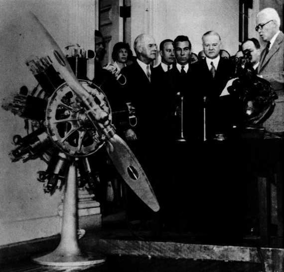
Frontispiece—President Herbert Hoover (in front of microphones) presenting the Collier Trophy to Alvan Macauley (nearest engine), President of the Packard Motor Car Co., on March 31, 1932 (although the award was for 1931). Also present were Hiram Bingham, U.S. Senator from Connecticut (nearest pillar), Clarence M. Young, Director of Aeronautics, U.S. Department of Commerce (between Macauley and Hoover), and Amelia Earhart, first woman to fly across the Atlantic Ocean (between Macauley and the engine). In the foreground is a cutaway Packard diesel aeronautical engine and directly in front of Senator Bingham is the Collier Trophy, America’s highest aviation award. (Smithsonian photo A48825.)

The following microfilm prints are available at the Smithsonian Institution:
“The Packard Diesel Aircraft Engine—A New Chapter in Transportation Progress.” An advertising brochure produced by the Packard Motor Car Company in 1930, illustrated, 17 pages.
Fifty-Hour Test of the Engine by the Packard Company, 1930. Text and charts, 14 pages.
Fifty-Hour Test of the Engine by the U.S. Navy in 1931: Text and charts, 26 pages.
Packard Instructional Manual, 1931. Illustrated, 74 pages.
“The Packard Diesel Engine,” Aviation Institute of U.S.A. Pamphlet No. 21-A, 1930. Illustrated, 32 pages.
For sale by the Superintendent of Documents, U.S. Government Printing Office
Washington, D.C., 20402—Price 60 cents
| Page | ||
| Acknowledgments | vi | |
| Foreword | vii | |
| Introduction | 1 | |
| History | 2 | |
| Description | 11 | |
| Specifications | 11 | |
| Operating Cycles | 13 | |
| Weight-Saving Features | 15 | |
| Diesel Cycle Features | 20 | |
| Development | 23 | |
| Comments | 27 | |
| Analysis | 33 | |
| Advantages | 33 | |
| Disadvantages | 35 | |
| Appendix | ||
| 1. Agreement Between Hermann I. A. Dorner and Packard Motor Car Company | 43 | |
| 2. Packard to Begin Building Diesel Plane Engines Soon | 46 | |
| 3. Effect of Oxygen Boosting on Power and Weight | 47 |
It is difficult to acknowledge fully the assistance given by persons and museums for the preparation of this book. However, I wish especially to thank Hugo T. Byttebier, engine historian, Buenos Aires, Argentina; Dipl. Ing. Hermann I. A. Dorner, diesel designer, Hanover, Germany; Harold E. Morehouse, and C. H. Wiegman, Lycoming Engines, Williamsport, Pennsylvania; Barry Tully, Goodyear Aircraft, Akron, Ohio; Richard S. Allen, aviation author, Round Lake, New York; William H. Cramer, brother of Parker D. Cramer, Wantagh, New York; Erik Hildes-Heim, Early Bird and aviation historian, Fairfield, Connecticut.
I am particularly grateful to curators of the following museums who have been so generous in their assistance: Deutsches Museum, Munich, Germany (Dipl. Ing. W. Jackle); Henry Ford Museum, Dearborn, Michigan (Leslie, R. Henry); U.S. Air Force Museum, Wright-Patterson Air Force Base, Dayton, Ohio (Maj. Robert L. Bryant, Jr., director); Science Museum, London, England (Lt. Comdr. (E) W. J. Tuck, Royal Navy). The preparation of this paper could not have been accomplished without the aid of the National Air Museum of the Smithsonian Institution and the help of Philip S. Hopkins, director, and Paul E. Garber, head curator and historian.
In this second number of the Smithsonian Annals of Flight, Robert B. Meyer Jr., curator and head of the flight propulsion division, tells the story of the first oil-burning engine to power an airplane, the Packard diesel engine of 1928, now in the collections of the National Air Museum.
The author’s narrative, well illustrated with drawings and photographs, provides a historical background for the development of the engine, and a technical description that includes specifications and details of performance. It also contains comments from men and women who flew planes powered by the Packard diesel. The author concludes with an analysis of the engine’s advantages and disadvantages.
Philip S. Hopkins
Director, National Air Museum
30 July 1964
On display in the National Air Museum, Smithsonian Institution, is the first oil-burning engine to power an airplane. Its label reads: “Packard Diesel Engine—1928—This first compression-ignition engine to power an airplane developed 225 hp at 1950 revolutions per minute. It was designed under the direction of L. M. Woolson. In 1931, a production example of this engine powered a Bellanca airplane to an 84 hour and 33 minute nonrefueled duration record which has never been equalled.—Weight/power ratio: 2.26 lb per hp—Gift of Packard Motor Car Co.”
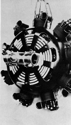
 | 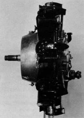 |
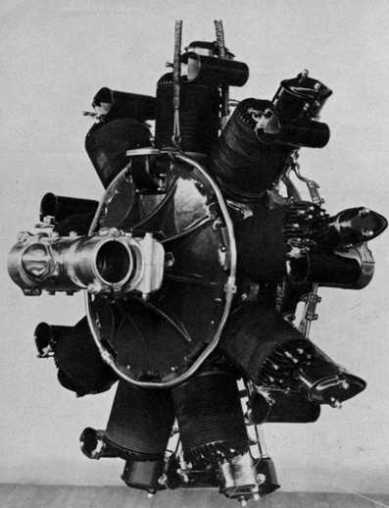
Figure 1 (left).—Front view of first Packard diesel, 1928. Note hoop holding cylinders in place and absence of venturi throttles. This engine was equipped with an air pressure starting system. (Smithsonian photo A2388.)
Figure 2 (right).—Left side view of first Packard diesel, 1928. Heywood starter (air) fitting shown on the head of the next to lowest cylinder. (Smithsonian photo A2388C.)
[Pg 2]This revolutionary engine was created in the short time of one year. Within two years of its introduction in 1928, airplane diesel engines were being tested in England by Rolls-Royce, in France by Panhard, in Germany by Junkers, in Italy by Fiat, and in the United States by Guiberson. Packard had demonstrated to the world the remarkable economy and safety of the airplane diesel engine, and the response was immediate and favorable. The novelty and performance of the Packard diesel assured it a large and attentive audience wherever it was exhibited. Yet in spite of its performance record the engine was doomed to failure by reason of its design, and it was further handicapped by having been rushed into production before it could be thoroughly tested.
The official beginning of the Packard diesel engine can be traced to a license agreement dated August 18, 1927, between Alvan Macauley, president of the Packard Motor Car Company of Detroit, Michigan, and Dipl. Ing. Hermann I. A. Dorner, a diesel engine inventor of Hanover, Germany.[1] Before the agreement was drawn up, Capt. Lionel M. Woolson, chief aeronautical engineer for Packard, tested an air-cooled and a water-cooled diesel that Dorner had designed and built in Germany.[2] Both engines attained the then high revolutions per minute of 2000 and proved efficient and durable. They demonstrated the practicability of Dorner’s patented “solid” type of fuel injection which formed the basis of the Packard diesel’s design.[3] Using elements from Dorner’s engines, Woolson and Dorner designed the Packard diesel with the help of Packard engineers and Dorner’s assistant, Adolph Widmann. Woolson was responsible for the weight-saving features, and Dorner for the combustion system.
The historic first flight took place on September 19, 1928, at the Packard proving grounds in Utica, Michigan, just a year and a month from the day Dorner agreed to join the Packard team. Woolson and Walter E. Lees, Packard’s chief test pilot, used a Stinson SM-1DX “Detroiter.” The flight was so successful, and later tests were so encouraging, that Packard [Pg 3]built a $650,000 plant during the first half of 1929 solely for the production of its diesel engine. The factory was designed to employ more than 600 men, and 500 engines a month were to have been manufactured by July 1929.[4]
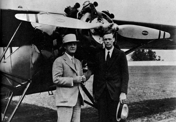
Figure 3.—Alvan Macauley (left), President of the Packard Motor Car Co. and Col. Charles A. Lindbergh with the original Packard diesel-powered Stinson “Detroiter” in the background, 1929. (Smithsonian photo A48319D.)
The engine’s first cross-country flight was accomplished on May 13, 1929, when Lees flew the Stinson SM-1DX “Detroiter” from Detroit, Michigan, to Norfolk, Virginia, carrying Woolson to the annual field day of the National Advisory Committee for Aeronautics at Langley Field. The [Pg 4]700-mile trip was flown in 6½ hours, and the cost of the fuel consumed was $4.68. Had the airplane been powered with a comparable gasoline engine, the fuel cost would have been about 5 times as great.[5] On March 9, 1930, using the same airplane and engine, Lees and Woolson flew from Detroit, Michigan, to Miami, Florida, a distance of 1100 miles in 10 hours and 15 minutes with a fuel cost of $8.50. The production engine, slightly refined from the original, received the first approved type certificate issued for any diesel aircraft engine on March 6, 1930. The Department of Commerce granted certificate no. 43 after the Packard Company had ground- and flight-tested this type of engine for approximately 338,000 hp hr, or about 1500 hr of operation.[6]
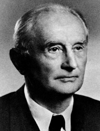 | 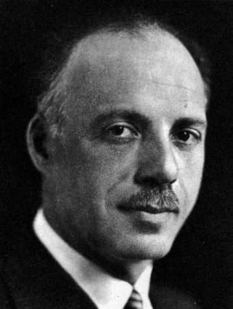 | |
| Figure 4.—Dipl. Ing. Hermann I. A. Dorner, 1930. German diesel engine designer, was responsible for the Packard DR-980 aircraft engine. (Smithsonian photo A48645.) | Figure 5.—Capt. Lionel M. Woolson, 1931. Chief Aeronautical Engineer, Packard Motor Car Co. Designer of Packard DR-980 diesel engine. (Smithsonian photo A48645A.) |
One of the early production versions powered a Bellanca “Pacemaker” which was piloted by Lees and his assistant Frederic A. Brossy to a world’s [Pg 5]nonrefueling heavier-than-air duration record. The flight lasted for 84 hours, 33 minutes from May 25 through 28, 1931, over Jacksonville, Florida. This event was so important that it was the basis of the following editorial, published in the July 1931 issue of Aviation,[7] which summarizes so well the progress made by the diesel engine over a 3-year period and the hope held for its future:
A RECORD CROSSES THE ATLANTIC—The Diesel engine took its first step toward acceptance as a powerplant for heavier-than-air craft when, in the summer of 1928, a diesel-powered machine first flew. The second step was made at the 1930 Detroit show, when the engine went on commercial sale. The third was accomplished last month, when a plane with a compression-ignition engine using furnace oil as a fuel circled over the beaches around Jacksonville for 84 hours and inscribed its performance upon the books as a world’s record—the longest flight ever made without intermediate refueling.
With the passing of the refueling-duration excitement, and with the apparent decision to allow that record to stand permanently at its present level, trials for straight time in the air without replenishment of supplies begin to regain a proper degree of appreciation. No other record, unless it be some of those for speed with substantial dead loads, is of such importance as the non-stop distance and duration marks. No other has such bearing upon precisely those qualities of aerodynamic efficiency, fuel economy, and reliability of airplane and powerplant that most affect commercial usefulness. It is more than three years since the duration record left American shores, and it has been more than doubled in that time. Its return is very welcome.
It is doubly welcome for being made with a fundamentally new type of engine. The diesel principle is not a commercial monopoly. It is open to anyone. Already two different designs in America, and one or two in Europe, have been in the air. For certain purposes, at least, it seems reasonable to expect that its special advantages will bring it into widespread use. Every practical demonstration of the progress of the diesel toward realizing its theoretical possibilities in the air as it has realized them on the land and at sea is a bit of progress toward better and more economical commercial flying, and so benefits the whole industry. The fourth, and next, main element in the demonstration will be provided when diesels go into regular service on some well-known transport line as standard equipment, and the accumulation of data on performance under normal service conditions begins. We believe that that will happen before the end of 1932.
Many men, from Dr. Rudolf Diesel to Walter Lees and Frederic Brossy, have had direct or indirect hands in the making of this record. The greatest of all contributions was that of Lionel M. Woolson, who created the engine and flew with it in every test and brought it through its early troubles to the point of readiness for the commercial market. The flight that lasted four days and three nights is his memorial, quite as much as is the bronze plaque unveiled last April in the Detroit show hangar.
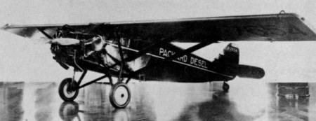 | Figure 6.—Stinson SM-1DX “Detroiter.” This airplane, powered with original Packard DR-980 diesel engine, made the world’s first diesel-powered flight on September 19, 1928. (Photo courtesy of Henry Ford Museum, Dearborn, Michigan.) | |
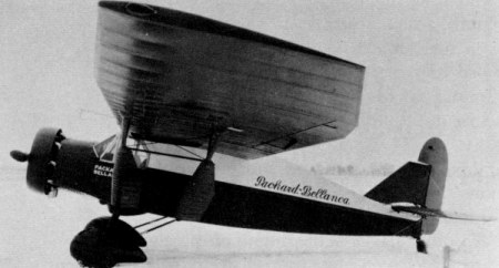 | Figure 7.—Packard-Bellanca “Pacemaker.” This airplane, powered by a Packard DR-980 diesel, holds the world’s record for nonrefueling, heavier-than-air aircraft duration flight. The flight lasted 84 hours, 33 minutes, 1¼ seconds, and was completed on May 28, 1931, Jacksonville, Florida. (Smithsonian photo A48446B.) | |
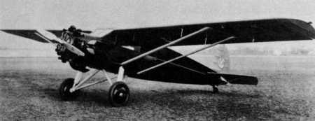 | Figure 8.—Verville “Air Coach,” October 1930. (Smithsonian photo A48844.) | |
 | Figure 9.—Packard-Bellanca “Pacemaker” owned by Transamerican Airlines Corporation and used by Parker D. Cramer, pilot, and Oliver L. Paquette, radio operator, in their flight from Detroit, Michigan, to Lerwick, Shetland Islands, summer 1931. (Smithsonian photo A200.) | |
[Pg 7] | Figure 10.—Ford 11-AT-1 Trimotor, 1930, with 3 Packard 225-hp DR-980 diesel engines. Note special bracing for the outboard nacelles. (Smithsonian photo A48311B.) | |
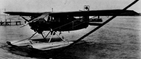
 | Figure 11.—Towle TA-3 Flying Boat, 1930, with 2 Packard 225-hp DR-980 diesel engines. (Smithsonian photo A48319.) | |
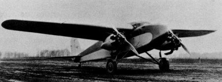 | Figure 12.—Stewart M-2 Monoplane, 1930, with 2 Packard 225-hp DR-980 diesel engines. (Smithsonian photo A48319C.) | |
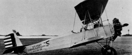 | Figure 13.—Consolidated XPT-8A, 1930. This is a Consolidated PT-3A powered by a DR-980 Packard diesel. (Smithsonian photo A48319E.) |
[Pg 8]The Robert J. Collier Trophy, America’s highest aviation award, was won by the Packard Motor Car Company in 1931 for its development of the diesel engine. The formal presentation was made at the White House, March 31, 1932, by President Hoover on behalf of the National Aeronautic Association. Alvan Macauley, president of the Packard Motor Car Company, accepted the trophy, saying: “We do not claim, Mr. President, that we have reached the final development even though our diesel aircraft engine is an accomplished fact and we have the pioneer’s joy of knowing that we have successfully accomplished what had not been done before....”[8] The amazing early success of the Packard diesel is illustrated by the following chronological summary:
1927—License agreement signed between Alvan Macauley and Hermann I. A. Dorner to permit designing of the engine.
1928—First flight of a diesel-powered airplane accomplished.
1929—First cross-country flights accomplished.
1930—Packard diesels were sold on the commercial market and were used to power airplanes manufactured by a dozen different American companies.
1931—World’s official duration record for nonrefueled heavier-than-air flight. First flight across the Atlantic by a diesel-powered airplane.
1932—Packard diesels tested successfully in the Goodyear nonrigid airship Defender.[9] Official American altitude record for diesel-powered airplanes established (this record still stands).
In spite of this promising record, the project died in 1933. The December 1950 issue of Pegasus gave two reasons for the failure of the engine: “One blow had already been dealt the program through the accidental death of Capt. L. M. Woolson, Packard’s chief engineer in charge of the Diesel development, on April 23, 1930. Then the Big Depression took its toll in research work everywhere and Packard was not excepted.”
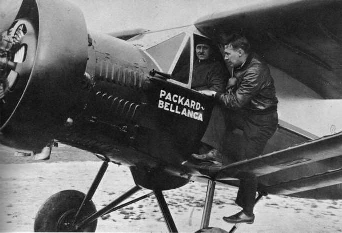
Figure 14.—Walter E. Lees, Packard chief test pilot (in cabin) and Frederic A. Brossy, Packard test pilot, before taking off on their world’s record, nonrefueling, heavier-than-air aircraft duration flight, which lasted 84 hours, 33 minutes, and 1¼ seconds. (Smithsonian photo A48446E.)
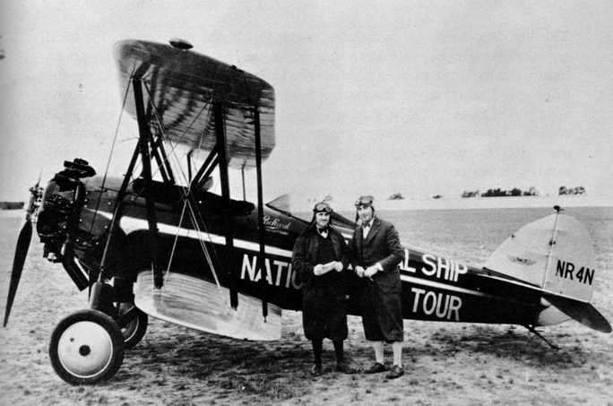
Figure 15.—Walter E. Lees, official timer, and Ray Collins, manager, 1930 National Air Tour, with their official airplane, a Packard diesel Waco “Taper Wing,” at Packard proving grounds near Detroit. (Smithsonian photo A49449.)
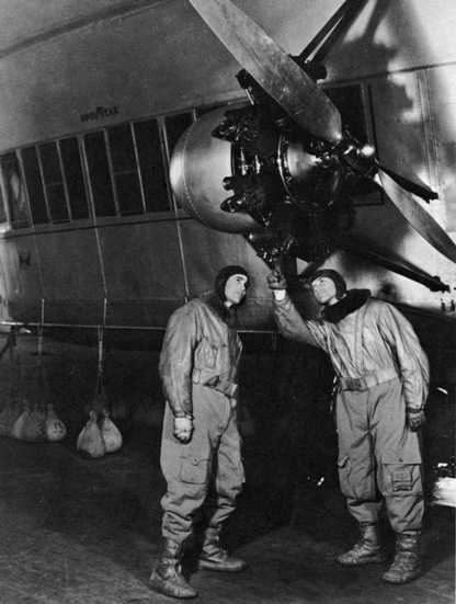
Figure 16.—Capt. Karl Fickes, acting head of Goodyear’s airship operations, pointing out features on one of the “Defender’s” Packard diesel engines to Roland J. Blair, Goodyear airship pilot, Akron, Ohio. From “Aero Digest,” February 1932. (Smithsonian photo A49674.)
The engine did not fail for the above mentioned reasons. Capt. Woolson’s death was indeed unfortunate, but there were others connected with the project who carried on his work for three years after he passed away. The big depression was also unfortunate, but it did not stop aeronautical engine development. “It was a time when such an engine would have been most welcome if it had been produced in large enough numbers to bring the price down to compare favorably pricewise with gas engines of the same horsepower class.”[10] The Packard diesel failed because it was not a good engine. It was an ingenious engine, and two of the several features it pioneered (the use of magnesium and of a dynamically balanced crankshaft) survive in modern reciprocating engine designs. In addition, when it was first introduced, no other engine could match it for economical fuel consumption and fuel safety. It also had other less important advantages, but its disadvantages outweighed all these advantages, as will be seen.
The following specifications are for the production engine and its prototypes, known as the model DR-980:[11]
| Type | 4-stroke cycle diesel | |
| Cylinders | 9—static radial configuration | |
| Cooling | Air | |
| Fuel injection | Directly into cylinders at a pressure of 6000 psi | |
| Valves | Poppet type, one per cylinder | |
| Ignition | Compression—glow plugs for starting—air compression 500 psi at 1000° F. | |
| Fuel | Distillate or “furnace oil” | |
| Horsepower | 225 at 1950 rpm | |
| Bore and stroke | 413⁄16 in. × 6 in. | |
| Compression ratio | 16:1—maximum combustion pressure 1500 psi | |
| Displacement | 982 cu in. | |
| Weight | 510 lb without propeller hub | |
| Weight-horsepower ratio | 2.26 lb hp | |
| Where manufactured | U.S.A. | |
| Fuel consumption | .46 lb per hp/hr at full power | |
| Fuel consumption | .40 lb per hp/hr at cruising | |
| Oil consumption | .04 lb per hp/hr | |
| Outside diameter | 4511⁄16 in. | |
| Overall length | 36¾ in. | |
| Optional accessories | Starter—Eclipse electric inertia; 6 volts. Special series no. 7 Generator—Eclipse type G-1; 6 volts |
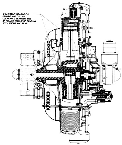 |  | |
| Figure 17.—Longitudinal cross section, Packard diesel engine DR-980. (Smithsonian photo A48845.) | Figure 18.—Transverse cross section, Packard diesel engine DR-980. (Smithsonian photo A48847.) | |
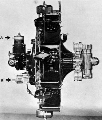
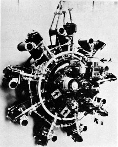
| Figure 19.—Right side view of engine, showing accessories; Packard Motor Car Co. 50-hour test, 1930. A, starter; B, oil filter. (Smithsonian photo A48323.) | Figure 20.—Rear left view of engine, showing accessories, U.S. Navy 50-hour test, 1931. Barrel valve type venturi throttles. A, starter; B, oil filter; C, fuel circulating pump; D, generator. (Smithsonian photo A48324C.) | |
 |  |
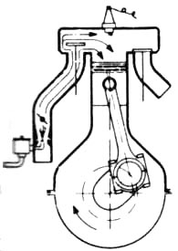
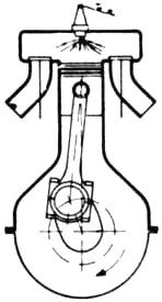
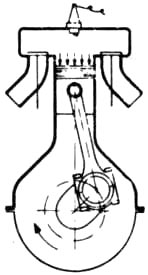
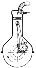
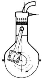
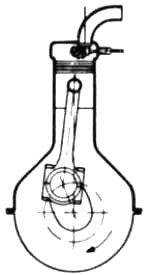
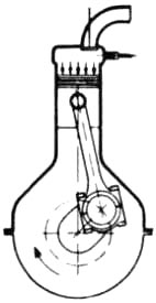
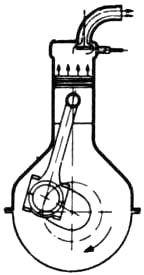
The sequences of operation of a Packard diesel engine compared with those of a 4-stroke cycle gasoline engine are illustrated in figure 21.
 |
 |
 |
 |
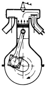 |
| Mixture of air and gasoline enters cylinder from carburetor. |
Mixture is compressed into smaller volume by piston moving upward. |
An electric spark ignites the compressed mixture causing it to explode. |
Combustion heat increases the cylinder pressure forcing piston downward. |
Momentum carries piston upward which pushes burnt gases out through the exhaust valve. |
 |
 |
 |
 |
 |
| Atmospheric air only, enters cylinder through single valve. |
Air is so greatly compressed by upward moving piston that it reaches temperature of 1000° F. |
Just before piston is at dead center fuel oil is sprayed into cylinder and spontaneously ignited. |
Power of this explosion is passed to crankshaft in conventional manner. |
Piston forces out burnt gases through same single valve which is cooled by inrush of new air as cycle repeats. |
Although the size, weight, and general arrangement of the Packard diesel did not differ radically from conventional gasoline engines of a similar type, there were definite differences caused by the diesel cycle. In the words of Capt. Woolson:[12]
[Pg 14]As this engine operates on an entirely different principle than the gasoline engines used heretofore in aircraft, it is desirable before launching into a mechanical description to consider first in a general way the principles of operation of the Diesel cycle as opposed to the Otto cycle principle on which nearly all gasoline engines operate.
The real point of departure between the two systems of operation is the ignition system involved. In the gasoline engine an electric spark is depended upon to fire a combustible mixture of gasoline vapor and air which mixture ratio must be maintained within rather narrow limits to be fired by this method....
In the Diesel engine, air alone is introduced into the cylinders, instead of a mixture of air and fuel as in the gasoline engine, and this air is compressed into much smaller space than is possible when using a mixture of gasoline and air, which would spontaneously and prematurely detonate if compressed to this degree. The temperature of the air in the cylinder at the end of the compression stroke of a Diesel engine operating with a compression ratio of about 16:1 is approximately 1000 degrees Fahr., which is far above the spontaneous-ignition temperature of the fuel used. Accordingly, when the fuel is injected in a highly atomized condition at some time previous to the piston reaching the end of its stroke, the fuel burns as it comes in contact with the highly heated air, and the greatly increased pressures resulting from the tremendous increase in temperature brought about by this combustion, acting on the pistons, drive the engine, as in the case of the gasoline engine.
Summing up, the differences between the Diesel and gasoline engines start with the fact that the gasoline engine requires a complicated electrical ignition system in order to fire the combustible mixture, whereas the Diesel engine generates its own heat to start combustion by means of highly compressed air. This brings about the necessity for injecting the fuel in a well-atomized condition at the time that combustion is desired and the quantities of fuel injected at this time control the amount of heat generated; that is, an infinitesimally small quantity of fuel will be burned just as efficiently in the Diesel engine as a full charge of fuel, whereas in the gasoline engine the mixture ratio must be kept reasonably constant and, if the supply of fuel is to be cut down for throttling purposes, the supply of air must be correspondingly reduced. It is this requirement in a gasoline engine that necessitates an accurate and sensitive fuel-and-air metering device known as the carburetor.
The fact that the air supply of a Diesel engine is compressed and its temperature raised to such a high degree permits the use of liquid fuels with a high ignition temperature. These fuels correspond more nearly to the crude petroleum oil as it issues from the wells and this fact accounts for the much lower cost of Diesel fuel as compared to the highly refined gasoline needed for aircraft engines.
In order to be successful in aviation use, the modern lightweight diesel of the time had to have its weight reduced from 25 lb/hp to 2.5 lb/hp. This required unusual design and construction methods, as follows:
Crankcase: It weighed only 34 lb because of three factors: Magnesium alloy was used extensively in its construction, thus saving weight as compared [Pg 16]with aluminum alloy, which was the conventional material at this time. It was a single casting. This saved weight because heavy flanges, nuts, and bolts were dispensed with. The cylinders, instead of being bolted to the crankcase, as was normal practice, were held in position by two circular hoops of alloy steel passing over the cylinder flanges. They were tightened to such an extent that at no time did the cylinders transfer any tension loads to the crankcase. This type of fastening actually strengthened the crankcase in contrast to the usual method. For this reason it could be built lighter. The hoops did not always function well. “The first job[Pg 17] I ever did on the Towle was to patch the holes in the top and bottom of the hull when a cylinder blew off during run-up and nearly beheaded the pilot.”[13]
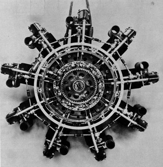
Figure 22.—Rear view of engine with rear crankcase cover removed, showing valve and injector rocker levers and injector control ring mounted on crankcase diaphram. U.S. Navy test, 1931. (Smithsonian photo A48323D.)

Figure 23.—Main crankcase. U.S. Navy test, 1931. (Smithsonian photo A48325B.)
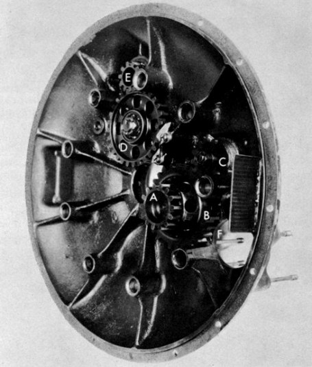
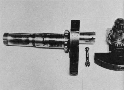
Figure 24.—Rear crankcase cover and gear train: crankshaft gear drives B, which drives oil pump at F. A, integral with B, drives internal cam gear. B also drives C on fuel-circulating pump. D, driven by crankshaft gear, drives E on generator shaft. U.S. Navy test, 1931. (Smithsonian photo A48325C.)
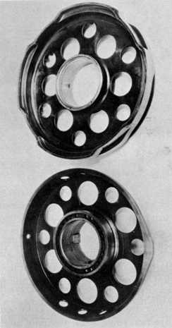
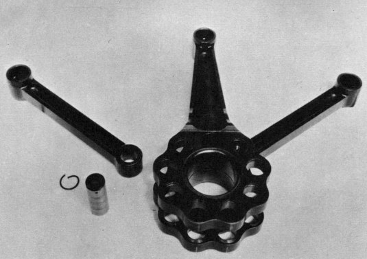 |  | |
| Figure 25.—Master and link connecting rods. U.S. Navy test, 1931. (Smithsonian photo A48323A.) | Figure 26.—Crankshaft with automatic-timing retarding device on rear end of pivoted- and spring-mounted counterweights. U.S. Navy test, 1931. (Smithsonian photo A48323B.) | |
 | ||
| Figure 27.—Propeller hub and vibration damper. U.S. Navy test, 1931. (Smithsonian photo A48325A.) | ||
Crankshaft: Since this engine developed the high maximum cylinder pressure of 1500 psi, it was necessary to protect the crankshaft from the resulting heavy stresses. Without such protection the crankshaft would be too large and heavy for practical aeronautical applications. Although the maximum cylinder pressures were 10 times as great as the average ones, they were of short duration. The method of protecting the crankshaft took full advantage of this fact. It consisted of having the counterweights flexibly mounted instead of being rigidly bolted, as was common practice. The counterweights were pivoted on the crank cheeks. Powerful compression springs absorbed the maximum impulses by permitting the counterweights to lag slightly, yet forced them to travel precisely with the crank cheeks at all other times.
Propeller Hub: The propeller is, of course, subject to the same stresses as the crankshaft. Instead of being rigidly bolted to the shaft as was common practice, it was further protected from excessive acceleration forces by being mounted in a rubber-cushioned hub. This permitted the use of a lighter propeller and hub.
Valves: A further weight saving resulted from the use of a single valve for each cylinder instead of two as in the case of conventional gasoline aircraft engines. (A diesel engine designed in this manner loses less efficiency than a gasoline one because only air is drawn in during the intake stroke.) In addition to the weight saving brought about by having fewer parts in the valve mechanism, there was an additional advantage since the cylinder heads could be made considerably lighter.
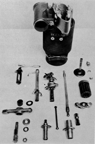
| Figure 28.—Cylinder disassembly, showing valve and fuel injector. U.S. Navy test, 1931. (Smithsonian photo A48324D.) |
 |
Although Woolson designed the ingenious weight-saving features, Dorner was responsible for the engine’s diesel cycle which employed the “solid” type of fuel injection. In order to understand Dorner’s contribution, a brief description of the type of diesel injection pioneered by Dr. Rudolf Diesel is necessary. His system injected the fuel into the cylinder head with a blast of air supplied by a special air reservoir at a pressure of 1000 psi or more. Known as the “air blast” type of injection it produced good turbulence, with the fuel and air thoroughly mixed before being ignited. Such mixing increases engine efficiency, but it involves the provision of bulky and costly air-compressing apparatus which can absorb more than 5 percent of the engine’s power. Naturally the compressor also adds considerably to the engine’s weight.
In contrast to this, a “solid” type of fuel injection may be employed to eliminate the complications of the “air blast” system. It consists of injecting only fuel at a pressure of 1000 psi or more. Air is admitted by intake stroke, as with a gasoline engine. Turbulence is induced by designing the combustion chamber and piston so as to give a whirling motion to the air during the intake stroke. The following quotation from Dorner now becomes readily understandable. “Since 1922 my invention consisted in eliminating the highly complicated compressor and in injecting directly such a highly diffused fuel spray so that a quick first ignition could be depended upon. By means of rotating the air column around the cylinder axis, fresh air was constantly led along the fuel spray to achieve completely sootless burning-up.... In 1930 I sold my U.S.A. patents to Packard.”[14]
Valve Ports: The inlet port (which was also the exhaust port) was arranged tangentially to the cylinder. This design imparted a very rapid whirling motion to the incoming air, thereby aiding the combustion process. Engine efficiency and rpm were both increased.
Fuel Injector Pumps: A combination fuel pump and nozzle was provided for each cylinder in contrast to the usual system of having a multiple pump unit remotely placed with regard to the nozzles. The former system was adopted after frequent fuel-line failures were experienced due to the engine’s vibration. Woolson stated that his system prevented pressure waves, which interfered with the correct timing of the fuel injection, from forming in the tubing. Leigh M. Griffith, vice president of Emsco Aero, writing in the September 1930, S.A.E. Journal stated: “Regarding the superiority claim [Pg 21]for the simple combination of fuel pump and injection valve into one unit, without connecting piping, the author entirely overlooks the fact that the elasticity of a pipe and its contained fuel can be important aids in securing that extremely abrupt beginning and ending of injection which is so desirable.”
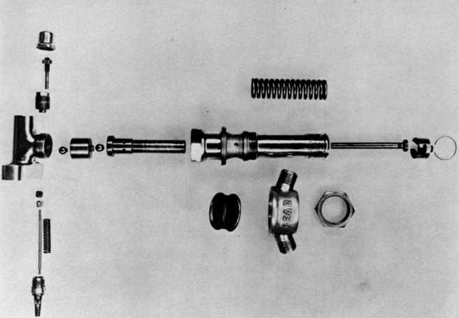
Figure 29.—Fuel-injector disassembly. U.S. Navy test, 1931. (Smithsonian photo A48323C.)
A major advantage obtained from combining the fuel pump and injection valve is the ability of an engine so equipped to burn a wide variety of fuels. The elimination of the above-mentioned type of high-pressure tubing reduces the possibility of a vapor lock occurring, thereby permitting more volatile fuels to be burned. This increases the range of hydrocarbon fuels the engine can utilize. It could run on any type of hydrocarbon from gasoline to melted butter.[15]
Another reason for combining the fuel pump and injection valve is given by P. E. Biggar in Diesel Engines (published in 1936 by the Macmillan Company of Canada Ltd., Toronto): “In the Dorner pump, for example, the stroke of the plunger is changed by using a lever-type lifter and moving the push-rod along the lever to vary its movement. Unfortunately, in all arrangements of this sort, the plunger comes to a reluctant and weary stop, as the roller of the lifter rounds the nose of the cam. When the movement does finally end, the injection does not necessarily stop, as the compressed fuel in the injection pipe is still left to dribble miserably into the combustion [Pg 22]chamber. To minimize this defect, the designer has placed the pump and injector together in a single unit.”
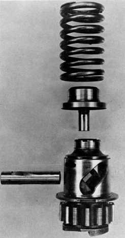 |  | |
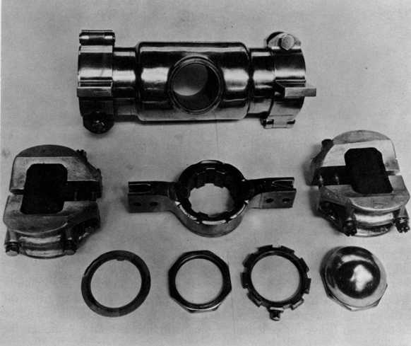
| Figure 30.—Mechanism for retarding valve and fuel-injection timing during starting (see also fig. 26). U.S. Navy test, 1931. (Smithsonian photo A48324E.) |
Figure 31.—Upper—valve and fuel injector cam; lower—fuel-injector cam used for starting. U.S. Navy test, 1931. (Smithsonian photo A48325.) |
Starting System: On November 1, 1961, C. H. Wiegman, vice president of engineering of the Lycoming Division of Avco Corporation wrote to the Museum in part as follows:
Early in the development it became quite evident that cold starting was a problem. This was finally worked out by Packard through the use of glow plugs and speeding up the injectors during the cranking period. It had been[Pg 23] felt that during the slow cranking process we were not vaporizing the fuel through the nozzles and that if we could speed up the injection pumps during this period of cranking a better vaporization could be obtained. Our tests showed that we were right, and that the engine could be started quite easily at minus 10° F through the use of glow plugs. The method used for speeding up the injection pumps was accomplished by utilizing a crankshaft cam during the cranking period. The starter would shift the running cam out of position allowing the crankshaft cam to take over. After the engine fired, the starter was disengaged and the running injector pump cam would assume its original position. The starting cam would be run at engine speed during cranking, and the running cam at ⅛ reverse engine speed during engine operation. The shifting was accomplished by a pin-in-slot and spring arrangement to change the indexing of the cams to starting position and return.
An Eclipse electric starter with an oversized flywheel was used.... This was powered by a double-sized battery.
Air Shutters: The first engines had no provision for throttling the intake air. This allowed the engine to run on its own lubricating oil when the throttle was in idle position. As a result the engine idled too fast, thereby causing either excessive taxiing speeds or rapid brake wear. This inability to idle slowly also caused high landing speeds since the propeller did not turn slowly enough to act as an airbrake. Figure 1 shows the first model. Note that the tubular air intakes on top of the cylinders have no valves. Figure 32 shows a later model. Note the butterfly valves in the ∪-shaped air intakes. Here they are shown fully opened. When the throttle was placed in idle position these valves automatically closed and prevented air from flowing past them. Air could then only enter from the back of the intakes. Since less air could flow into the cylinders, the force of their explosions was reduced, which, in turn, lowered the idling revolutions per minute. Figure 28 shows a cylinder from a more advanced model. Note the circular opening between the air intake and the intake/exhaust housing. A barrel type of valve fitted into this opening. One of these valves can be seen just below and to the left of the cylinder. When the throttle was placed in idle position this valve rotated to a position which cut off almost all of the airflow into its cylinder. This increased the vacuum formed toward the end of the intake stroke, thereby causing more resistance, which reduced the idling rpm to that of a gasoline engine.[16]
 |  | |
| Figure 32.—Front left view of engine from Packard Motor Car Co. 50-hour test, 1930, showing butterfly valve type venturi throttles. (Smithsonian photo A48325E.) |
Figure 33.—Front left view of engine from U.S. Navy test, 1931, showing spiral oil cooler. (Smithsonian photo A48324A.) |
Crankcase: It was strengthened by having external ribs added. Note the contrast between the first engine, figure 2, and a later model, figure 32.
Oil Cooler: The drum-shaped honeycombed cooler was replaced by a spiral pipe type located between the engine cowl and the crankcase. Figure 3 shows an example of the former type of cooler located at the top of the engine between two of the cylinders. Figure 33 illustrates the latter type located between the cowling and the crankcase.
Cylinder Fastening: Early models had their cylinders strapped and bolted to the crankcase. Later ones had them only strapped. Figure 2 shows a bolt-fastened clamp between two of the cylinders on the first engine. Figure 19 shows a later model without any bolts holding down the cylinders.
Pistons: The pistons used in the 1929 engine had one compression ring and one oil scraper ring above the piston pin, and one oil scraper ring[Pg 25] below it. There were three grooves, two above the piston pin, and one below it.[17] Pistons used in 1930 had two compression rings, one oil scraper ring above the piston pin, and one oil scraper ring below it. There were four grooves, three above the piston pin, and one below it.[18] The 1931 pistons had one compression ring above the piston pin, and one compression ring and four oil scraper rings below it. There were four grooves, one above the piston pin, and three below it.[19]
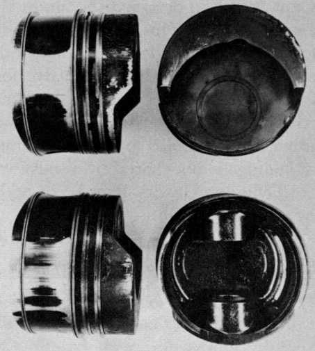
Figure 34.—Modified pistons after endurance run. U.S. Navy test, 1931. (Smithsonian photo A48325D.)
Combustion Chamber: In 1931 the contour of the cylinder head was changed slightly. This improved the combustion efficiency to the extent that the stroke of the fuel pumps could be decreased about 15 percent. The specific fuel consumption then decreased about 10 percent. In addition the compression ratio was reduced from 16:1 to 14:1.[20]
These changes were designed to eliminate smoke from the exhaust at cruising speed, and to reduce it at wide-open throttle.
Valves: A two-valve-per-cylinder model was built, but not put into production. It featured more horsepower (300), a higher rate of revolutions per minute (2000), and a better specific fuel consumption (about .35 lb/hp/hr).[21]
[Pg 26]Capt. Woolson designed the production model with a single large valve for each cylinder. This was done in order to shorten the development period, for it is easier to design a single valve which serves both the intake and exhaust functions than one valve for each function. Not only are there fewer parts, but more important, there are no heat-dissipating problems. Although the single valve is heated when it releases the exhaust gases, it is immediately cooled by the incoming air of the next cycle. This cooling advantage is not shared by a valve which only passes exhaust gases.[22]
Cylinder Head: Ribs were added to increase its rigidity (compare fig. 32 with fig. 33).
Engine Size: A 400-hp model was developed in 1930. It was not put into production.[23]
Comments of Aeronautical Engineers: These comments appeared in Aviation for February 15, 1930, just a month before the Packard diesel received its approved-type certificate. They were in answer to the question, “What is your opinion of the probable early future of the compression ignition type of engine in aircraft powerplants?” Most of the engineers were enthusiastic about the diesel engine’s future in aviation; however, neither George J. Mead nor C. Fayette Taylor shared their colleagues’ opinions. Mead’s prophesy was accurate except for his discounting the diesel’s role in lighter-than-air craft. Taylor was correct in implying that there was a future for the diesel in powering airships.
George J. Mead (vice president and technical director, Pratt & Whitney Aircraft Company):
Compared with the present Otto cycle engine, the Diesel powerplant weight, including fuel for a long-distance flight, would apparently be less. It is doubtful whether there would be any saving if the orthodox engine were operated on a more suitable fuel. Inherently the Diesel engine must stand higher pressures and therefore is heavier per horsepower. A partial solution of this difficulty is the two-cycle operation, which seems almost a requirement if the Diesel cycle is to be considered at all for aircraft. For any normal commercial operation in the United States there seems to be little or no improvement to be had from the Diesel. After all, it is not entirely a question of fuel cost but payloads carried for a given horsepower. It seemed at one time as though the Diesel was particularly desirable for Zeppelin work. Now that blau gas has been introduced, which obviates the need of valving precious lifting gas, the Diesel cycle seems much less interesting for this purpose. There may be a reduction in fire hazard and radio interference with the Diesel cycle, but it is doubtful whether it will be used in view of these considerations alone.
C. Fayette Taylor (professor of aeronautical engineering, Massachusetts Institute of Technology): “I believe that the compression ignition engine will continue to remain in the experimental stage during the year 1930. I should expect its first really practical installation to be in lighter-than-air craft.”
[Pg 28]P. B. Taylor (acting chief engineer, Wright Aeronautical Corporation): “I believe the compression ignition engine is probably the type which will eventually supersede the present electric ignition units. This development will come slowly and will not be a solid injection engine.”
Henry M. Mullinnix (former chief of powerplant section, Navy Bureau of Aeronautics):
The advantages of compression-ignition, including reduced fire hazard, more efficient cycle, elimination of electrical apparatus and hence of radio interference, elimination of carburetion problems, and other benefits less evident, would seem to outweigh the difficulties encountered in metering and injecting minute quantities of fuel at the proper instant. Although the Diesel engine suffers upon comparison with the Otto cycle engine in flexibility there seems to be a definite field for employment of Diesels and a gradual extension of their use may be predicted.
John H. Geisse (chief engineer, Comet Engine Corporation): “I am firmly convinced that the Diesel engine in the future will not only maintain the advantages of Diesel engines as they are now known, but will also be lighter in pounds per horsepower than the present Otto engines.”
Lt. Cdr. C. G. McCord (U.S. Navy, Naval Aircraft Factory): “The use of compression ignition in due time appears to be assured; but increase in weights above those of present Otto cycle engines, to insure reliability, must be expected.”
L. M. Woolson (aeronautical engineer, Packard Motor Car Company): “There is no question that the compression ignition aircraft engine will in time offer severe competition to the gasoline engine. There are, however, many basic problems to be solved for the solution of which there exists no precedent.”
N. N. Tilley (chief engineer, Kinner Airplane and Motor Corp.):
Considerable development of the compression ignition type of engine for aircraft will be required before it is commonly available. It is believed that the weight per horsepower must be equal to, or less than, that of the present type of engines, in order to interest the public, since rapid take-off, rate of climb, and speed are desired, rather than low fuel consumption or high mileage. Most flights are of few hours duration. It is believed that flights must be of over five or six hours duration in order to show any advantage of Diesel engines (with low fuel consumption) if appreciably heavier than present engines. Also the difference between Otto cycle and Diesel becomes slight as the compression ratios come closer together.
Comments of Flight Crews: The preceding comments were made by engineers thinking primarily of the commercial possibilities of the diesel. Following are comments by flight crewmembers about the operating[Pg 29] characteristics of the Packard diesel. The former were largely optimistic. Most of them were only familiar with the aeronautical diesel as a design project and therefore did not have the practical experience necessary to understand all of its limitations. The latter were pessimistic, as they knew firsthand various shortcomings of the engine which only became apparent when it was operated.
Clarence D. Chamberlin, pioneer pilot:
My only experience with the Packard diesel was in a Lockheed “Vega” which I owned back about 1932. The Wright J-5 had been replaced with the 225 hp Packard Diesel. My main complaint was the excessive fumes. When I would come home at night my wife would greet me with, “You have been flying that oil burner again.” It was so bad that passengers’ clothing would smell like a smoky oil stove for hours after a flight.
Looking backward, it is my guess that the Diesel would have had only a limited period of acceptance even if all mistakes had been avoided. It is easier and cheaper to get performance with lighter and more powerful engines and longer runways than by refining the airplane. Fuel economy of an engine has ceased to be the deciding factor. Higher utilization of a high speed Jet at least in part offsets the inefficient use of fuel. The only time the Diesel had a chance was from the middle 20’s perhaps on thru WW-2 for certain things due to gasoline shortage. To sum it up, the thing that licked them worst was the use of a single valve for inlet and exhaust making it impossible to collect and keep the fumes out of the fuselage.[24]
Ruth Nichols, prominent aviatrix:
I was flying Chamberlin’s diesel-powered Lockheed, in which a month before I had made an official altitude record for both men and women in aircraft powered by an engine of that type. The record, I believe, still holds. It was a rugged, dependable plane whose experimental oil-burning engine nevertheless had a number of bugs. For one thing, it was constantly blowing out glow-plugs used for warming the fuel mixture, and when that happened long white plumes of smoke would stream out, giving spectators the impression that the ship was on fire. For another, the vibration was so bad that out of 10 standard instruments on the plane, 7 were broken from the jarring before my return. The diesel fuel also produced a strong odor in the cockpit, the fumes so permeating my luggage and clothes that my public appearances during the tour always were highly and not very agreeably aromatic. Having a strong stomach, I soon became accustomed to the fumes, but another pilot who ferried the plane between cities for me on one occasion ... was almost overcome. On arrival he said, “I wouldn’t fly that oil burner another mile.”[25]
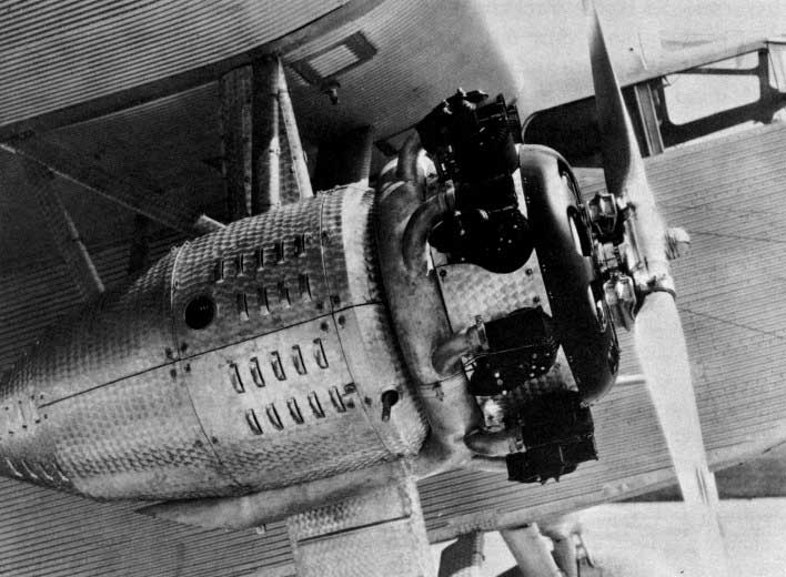
Figure 35.—Ford 11-AT-1 Trimotor, 1930, with 3 Packard 225-hp DR-980 diesel engines, right side view of right engine nacelle. (Smithsonian photo A48311.)
Richard Totten,[26] airplane mechanic:
The Ford Trimotor was the poorest of the lot. It was inherently noisy and slow, and with the Packards installed it was on the point of being underpowered. It was almost impossible to synchronize the three engines, and the beat was almost unbearable. It was not flown much but it made a fine conversation piece standing on the airport apron....
The Waco taperwing developed the unnerving habit of breaking flying and landing wires from the vibration, and most of the time sat on the hangar floor with its wings drooping like a sick pigeon. In flight the open cockpit filled with exhaust smoke and unburned fuel and the pilot would land after an hour’s flight looking like an Indianapolis 500 Mile Race driver....
The Stinson “Detroiter,” the Bellanca “Pacemaker” and the Buhl-Verville “Airsedan” were the most successful ships and were the most used. The “Airsedan,” in which Woolson was killed, was his favorite ship, and the one I believe that was the most flown.
[Pg 31]The Towle TA-3 amphibian flew beautifully, but not for long. It never got a chance to do much as it was a victim of the depression. The Towle was powered by 2 Packard diesels on loan from the Packard Motor Car Company. It was built of corrugated aluminum exactly like the Ford Trimotor. As a matter of fact, Towle had been employed by Ford until Ford cancelled airplane building. Towle got his airplane built at the hangar on Grosse Isle in Detroit, and ran out of money during the flight testing program. He now looked for money to continue with and found a backer in the person of one Doctor Adams, a widely advertised “Painless Dentist” of Detroit. Adams wanted a quicker return on his money than the average backer and he insisted that Towle put the airplane in service so it could start earning some money. At this time the amphibian was beginning to become popular for intercity flying, especially around the Great Lakes region as all of the major cities were located on the waterfront. What was more natural than an airline flying passengers right into the downtown area of a city? Thompson was doing it between Detroit and Cleveland, Marquette was doing it between Detroit and Milwaukee, so Adams applied for permission to operate an airplane between Detroit and Cleveland and other cities on the lakes. In those days it was necessary to prove an airplane’s reliability by flying a certain number of trips over the proposed route with a simulated payload. This payload was supposed to consist of sand bags, but usually consisted of any mechanic or pilot who happened to be loose at the moment, and who had nerve enough to go along. Mechanics were easier to load and unload than sand bags.
The Towle was in the middle of the qualification flights, and the publicity began to appear about the new airline. Much newsprint was devoted to the fact that the Towle was powered by the new Packard diesel engine, and this, of course, made it the only safe airline since all its competitors were using the old-fashioned dangerous gasoline. On the last payload trip of the Towle the pilot asked me if I wanted to go along, and of course I was delighted. I neglected to mention that I had been hired by the Adams airline as a mechanic because of my experience in repairing the corrugated skin of the Ford Trimotor owned by my employer, the Knowles Flying Service. The mere fact that I did many repairs to the airframe did not preclude me from getting my share of the engine work too, and since I was already familiar with the Packard diesel, I was quickly hired by Dr. Adams.
The last flight was indeed the last flight. We took off from the Detroit City Airport and when we crossed the Detroit river the pilot decided to land at the Solvay Coal Company docks and fuel up for the opening of the airline the next day. The Solvay Coal Company was the only place in Detroit where diesel fuel was obtainable at the time and all of the diesel powered yachts got fuel there. The pilot was not too experienced in the operation of amphibians, and he put the wheels down as we approached the river. When we hit the water the airplane went over on its back and sunk to the bottom. It[Pg 32] came up to the surface again, and we all climbed out onto the keel, and waited for rescue. A police boat came over and took us to the dock. The police sent us to the hospital and then went back and towed the airplane over to the shipyard next door to Solvay. While we were at the hospital, the crane man hooked onto the Towle and lifted it out of the water and gently set it down on the dock. He was only trying to help, but he inadvertently set it down on its back instead of its wheels. That was the end of the Adams airline. The Packard Company took back their engines. I helped remove them the next day. We dismantled the airplane and trucked it back to the airport where it sat in a state of neglect for some time. The pilot was fired, I lost my job, and Towle lost his airplane.
A Packard diesel advertisement which appeared in Aero Digest for June 1930 stated that this engine had three major advantages over its gasoline rivals: Greater reliability because of extreme simplicity of design; greater economy because of lower fuel cost plus lower fuel consumption, permitting greater payloads with longer range of flight; and greater safety because of removal of the fire hazard through the use of fire-safe fuel and absence of electrical ignition equipment.
These were the engine’s principal advantages. Others are analyzed here by the author in order of their importance. At low altitudes the diesel uses an excess of air to eliminate a smoking exhaust; consequently at high altitudes, where the air is less dense, the diesel is still able to maintain much of its power. In contrast, the carburetored gasoline engine is sensitive to the fuel-air ratio and thus has no surplus air available at higher altitudes. A malfunctioning carburetor could cause a gasoline engine to cease operating, but an inoperative fuel injector would cause the Packard diesel to lose one ninth of its power, since each cylinder had its own independently operating injector. In practice, however, because of the excessive vibration, the engine was generally shut off immediately after a cylinder cut out.[27] Shielding was unnecessary because the diesel had no electrical ignition system. Carburetor icing was an impossibility because there was no carburetor.
Any excess lubricating oil in a diesel engine’s cylinder is consumed cleanly to produce power. By contrast, such oil in a gasoline engine’s cylinder is only partly burned. As a result carbon deposits form that eventually cause malfunctioning of the spark plugs, valves, and combustion chambers. This advantage accrued to the diesel because it utilized an excess of air, and in addition its cylinder walls were hotter. The engine was very clean-running from the standpoint of oil leakage. This was a safety factor since it eliminated the possibility of a fire starting on the outside surfaces of the engine, and in addition it saved the time and money that was normally spent cleaning engines.[28] Since the diesel utilized its heat of combustion more efficiently than the gasoline engine, its cooling fin area could be reduced by 35 percent. This permitted better streamlining. Having less cooling fin area, it warmed up more rapidly than a gasoline engine.
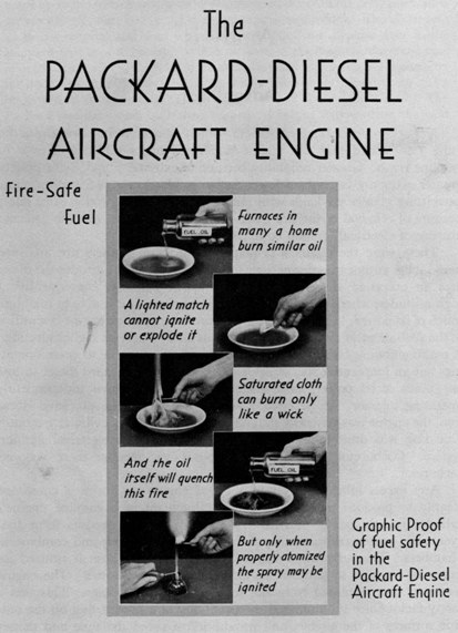
Figure 36.—Advertisement emphasizing the advantages of fire-safe fuel. (Smithsonian photo A48848.)
Due to the greater simplicity, it was more practical to build a large diesel than a large gasoline engine. Large airplanes would therefore need fewer engines if diesel powered. Smaller fuel tanks could be used because of the greater fuel economy of the diesel, and also because of the high specific gravity of fuel oil as compared to gasoline. Furthermore, these smaller tanks could be placed in more convenient locations. Not having a carburetor the engine could not backfire, further reducing the fire hazard. The exhaust note was lower because of the diesel’s higher expansion ratio. The absence of an ignition system permitted the diesel to operate in the heaviest types of precipitation. Such conditions might cause the ignition system of a gasoline engine to malfunction. The Packard diesel was flown at times without exhaust stacks or manifolds; this was practical from a safety standpoint because of the diesel’s lower exhaust temperature due to its higher expansion ratio. Elimination of these parts reduced the weight and cost of the engine installation. Finally, the engine was ideal for aerobatics, since the injectors, unlike carburetors, would work equally well whether right side up or upside down.
An advantage peculiar to the Packard among aeronautical diesels was its light weight. The English Beardmore “Tornado III” weighed 6.9 lb/hp, and the German Junkers SL-1 (FO-4) weighed 3.1 lb/hp, while the Packard weighed but 2.3 lb/hp. In fairness to the Beardmore, it was the only one of the three engines designed for airship use, and part of its heaviness was due to the special requirements of lighter-than-air craft. A contemporary and comparable American gasoline engine, the Lycoming R-680, weighed 2.2 lb/hp. To have designed a diesel aircraft engine as light as a gasoline one was a remarkable achievement.
There are four main reasons why the Packard diesel was not successful. First the Packard Motor Car Company put the engine into production a brief three years after it was created. The only successful airplane diesel, the German Junkers “Jumo,” was in development more than three times [Pg 36]as long (1912-1929). The following tests indicate that the Packard diesel was not ready for production, and hence was unreliable.
Packard Motor Car Company 50-Hour Test (Feb. 15-18, 1930): This test was identical to the standard Army 50-hour test which was used for the granting of the Approved Type Certificate. The engine tested was numbered 100, and was the first to be made with production tools (approximately half a dozen engines had been handmade previously). It had to be stopped three times, twice due to failure of the fuel pump plunger springs and once due to the loosening of the oil connection ring. These failures were attributed to manufacturing discrepancies. In addition, 4 out of a total of 103 valve springs broke.[29]
U.S. Navy 50-Hour Test (Jan. 22, 1931, to March 15, 1931): The engine used in the Navy test was numbered 120. (Apparently only 20 production engines had been built during the preceding 12 months; Dorner in a letter of March 3, 1962, states that the total number of Packard diesels produced was approximately 25.) The engine had to be stopped three times, twice due to valve-spring collar failures and once due to a valve head breaking. Because of these failures this test was not completed. The following significant quotations have been extracted from the test: “The engine is not recommended for service use.... Flight tests, until the durability of the engine is improved, be limited to a determination of the critical engine speeds, and to short hops in seaplanes.... It is believed that this size engine should be made suitable for service use before this type in a larger class is attempted.” This latter statement probably refers to the 400-hp model.
A year had passed between the making of engine 100 and 120, yet the reliability had not improved. Although unreliability was the immediate cause of failure, there were two design defects which would have doomed the engine even if it had been reliable. All the Packard diesels were of the 4-stroke cycle unblown type, yet the most successful airplane diesels were of the 2-stroke cycle blown type.[30] The advantages of the latter type for aeronautical use are that it is of a more compact engine, of lower [Pg 37]weight and greater efficiency.[31] The engine was therefore built around the wrong cycle.
The Packard diesel of 1928 was designed to compete with the Wright J-5 “Whirlwind” which powered Lindbergh’s “Spirit of St. Louis” in 1927.[32] The specifications were within two percent of each other. The diesel engine’s fuel consumption was far less although its price was considerably higher.
| Packard Diesel DR-980 | Wright J-5 “Whirlwind” | |||
| Diameter (in.) | 4511⁄16 | 45 | ||
| Horsepower | 225 | 225 | ||
| Weight (lb) | 510 | 510 | ||
| Weight-horsepower ratio | 2.26 | 2.26 | ||
| Fuel consumption (lb per hp/hr at cruising). | 0.40 | 0.60 | ||
| Cost | $4025 | $3000 |
The advantages of lower fuel cost and greater cruising range offered by the diesel engine would be relatively unimportant to a private pilot flying for pleasure, but would be vital to the commercial operator using airplanes powered by engines having several times the horsepower of the Packard diesel. Its size, moreover, was too small for the technology of fuel injectors.[33] The Packard Company realized that the production engine was too small.[34] In 1930 a 400-hp version was built but was not put into production, probably because of the unreliability of the 225-hp model.
The fourth principal reason why the engine failed is explained by the following quotation from The Propulsion of Aircraft, by M. J. B. Davy (published in 1936 by His Majesty’s Stationery Office, London):
Although the development and adoption for transport purposes of the relatively high-speed compression ignition engine has been rapid during the last few years, there has been no corresponding advance in its adoption for aircraft propulsion. A reason for this is the recent great advance in “take-off” power in the petrol (gasoline) engine due to the introduction of 87 octane fuel (which permits higher compression ratios) and the strong probability of 100 octane fuels in the near future, still further increasing this power. The need for increased take-off power results from the higher wing loading necessitated by the modern demand for commercial aircraft with higher cruising speeds with reasonable power expenditure.
[Pg 38]Production of the Packard diesel ceased in 1933. During that same year the Pratt & Whitney Aircraft Company and the Wright Aeronautical Corporation specified 87-octane fuel for certain of their engines. Less than 10 years later octane ratings had increased to over 100, putting the diesel at a further disadvantage.[35]
Although the above disadvantages sealed the Packard diesel’s fate, there were other minor reasons for its failure. The Packard diesel had the highest maximum cylinder pressure (up to 1500 psi at peak rpm) of any proven contemporary aircraft diesel engine. Leigh M. Griffith, vice president and general manager, Emsco Aero Engine Company, had this to say about the Packard diesel’s high maximum cylinder pressure in the September 1930 S.A.E. Journal:
The designers considered it necessary to adopt unusual but admittedly clever expedients to counteract the great torque irregularity caused by the excessive maximum pressure. The adoption of the lower pressure of 800 lbs. would have eliminated the necessity for the pivoted spring-mounted counterweights and the shock-absorbing rubber propeller-drive.... The use of such high pressures is in reality the quick and easy way to secure high-speed operation and can be justified only from this standpoint, although the resulting increased difficulty in keeping the engine light enough was a strong offsetting factor.[36]
Insofar as the engine life was concerned it is true that 1,500-psi peak pressures were observed but the engine was so developed to withstand these pressures.... One of the most severe problems connected with the development of this engine was the piston ring sealing. Special compression rings were made with no gaps and further work in this respect could have been used to advantage had the engine been kept in production.[37]
[Pg 39]It is significant that in 1930 the Packard diesel had a compression ratio of 16:1, whereas in 1931 it has been reduced to 14:1. This was probably done to reduce vibration and the problem of piston-ring sealing.[38] The exhaust products had an unpleasant odor which was particularly objectionable during taxiing. Professor C. Fayette Taylor, writing in the January 1931 issue of Aviation, remarked about this fault: “One is inclined to question whether the disagreeable escaping of exhaust gas from the intake ports can be overcome, while still retaining the obvious advantages in weight and simplicity of the single valve.” The engine exhaust deposited a black oily film. In fact some airplanes fitted with the Packard diesel engine were painted black, so that soot deposits from the exhaust would not be noticed.[39] Since the passengers’ and pilots’ compartments were generally located behind the engines, and were not airtight, damage to clothing resulted. This fault could have been eliminated by the use of separate valves for the intake and exhaust systems.
It was not possible to start the engine when the temperature dropped much below 32° F unless glow plugs were used. These spark-plug-like devices, which were only used for starting, had resistance windings which glowed continuously when turned on. The additional heat glow plugs provided made starting an easy matter in the coldest weather; however, they complicated the design of an engine noted for its simplicity, and they used so much electricity that only a long flight would allow the generator to fully recharge the battery.
H. R. Ricardo, writing in the June 4, 1930, issue of The Aeroplane said: “Referring to the very fine achievement of the Packard Company of America in producing a small radial air-cooled heavy-oil engine, a petrol engine of similar design and with the same margin of safety would weigh less than 1½ lbs. per hp.” The important point made is that a gasoline engine designed along the same lines as the Packard diesel would weigh considerably less, but would then suffer from the Packard’s reduced structural safety factor. It is significant that as the Packard developed, it became heavier.[40]
Like other diesels, the Packard cost more to build than a comparable gasoline engine, because of the type of construction required for the diesel’s higher maximum cylinder pressures and the difficulty of machining the fuel injectors. Having fuel injectors, the engine was more sensitive to [Pg 40]dirt in the fuel system than a carburetor-equipped gasoline engine.[41] The fuel injectors were “a crude and deficient mechanism” subject to rapid wear, and often these injectors caused smoking exhausts and high fuel consumptions.[42] In the event of battery or starter failure, a comparable gasoline engine could be started by swinging the propeller. Because of the engine’s high compression, it would have been impossible to have hand-started a Packard diesel this way.
In a letter to the Air Museum, January 15, 1962, Dorner commented: “During my first demonstration (of high-speed diesel engines) in 1926 in California and later in Detroit I learned from Capt. Woolson that the large transport airlines were controlled by oil companies which were not interested in (supplying) two different kinds of aircraft fuel, and in savings of fuel.” The May issue of Aero Digest had a full-page illustrated advertisement titled “Announcing National Distribution for Texaco Aerodiesel Fuel.” Although distribution was limited, the American oil industry did not prevent the airplane diesel from becoming a success in the civil market. However, it is significant that the advertisement was placed by Frank Hawks of the Texas Company largely as a gesture of friendship to Woolson.[43]
The situation in the military market was different, however, as testified by this quotation from the same letter. “The military administration, having paid all of the expenses for the testing period to that date (1931), came after the tests to the conclusion that the advantages of the diesel as compared to its disadvantages did not justify the great risk to procure and distribute two different kinds of fuel in case of war.”
Two accidents, which received wide publicity and no doubt did considerable harm to the entire project, occurred to Packard diesel-powered airplanes. The following quotation is from the Herald Tribune for April 23, 1930: “Attica, New York—Losing their bearings in a blinding snowstorm and mistaking the side of a snow-covered hill for a suitable landing place, three men, one of them Capt. Lionel M. Woolson, aeronautical engineer for the Packard Motor Company and adapter of the diesel engine to airplanes, were killed here today.”
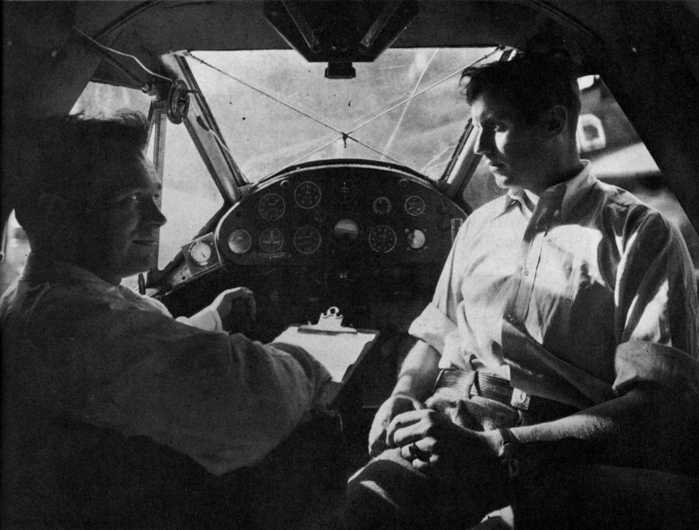
Figure 37.—Interior of Bellanca, showing Parker D. Cramer, pilot (left), and Oliver L. Paquette, radio operator, just before taking off from Detroit, Michigan, on July 28, 1931. (Smithsonian photo A202.)
The second of these accidents is described in the September 1931 issue of U.S. Air Services:
Columbus wanted to sail west beyond the limits set by the learned navigators of his time, and in much the same consuming fashion Parker D. Cramer wanted to show his generation and posterity that a subarctic air route to Europe via Canada, Greenland, Iceland, Norway, and Denmark was feasible.... On July 27, without any preliminary announcement, Cramer left Detroit in a Diesel-engined Bellanca, and following the course he took with Bert Hassel three years ago, he flew first to Cochrane, on Hudson Bay. His next stop was Great Whales and then Wakeham Bay. From there he flew to Pangnirtum, Baffin Land, and across the Hudson Straits to Holsteinborg, Greenland. He crossed the icecap at a point farther north than the routes that have been discussed heretofore, but almost on the most direct or Great Circle route from Detroit to Copenhagen. He was accompanied by Oliver Paquette, radio operator. They were on their way more than a week before they were discovered. To Iceland, to the Faroe Islands, to the Shetlands.
[Pg 42]They were taxiing across the little harbor of Lerwick, Shetland Islands, when a messenger from the bank waved a yellow paper. It was a warning of gales on the coast east to Copenhagen. Cramer apparently thought it was an enthusiastic bon voyage, and, after circling the town, flew away. A Swedish radio station reported a faint “Hello, Hello, Hello” in English, but the plane was not seen again.
As the result of a personal conversation with his brother, William A. Cramer, in 1964, the author learned that the fuselage and floats of the airplane were found six weeks later. Since there was no indication of a heavy impact (not a single glass dial on the instrument panel was broken), a successful landing must have been made. Several weeks later, a package was found wrapped in a torn oilskin containing instruments, maps, and a personal letter, all substantiating the evidence that the landing was successful. It can only be surmised that there was engine failure, probably due to a clogged oil filter.[44]
Once before during the trip a forced landing had been made due to engine malfunctioning, and a successful takeoff was accomplished in spite of a moderately rough sea. This time, however, storm conditions probably made the takeoff impossible.
As a final summary of the author’s analysis of the Packard diesel engine, it must be emphasized that although the engine burned a much cheaper and safer fuel more efficiently than any of its gasoline rivals, it was too unreliable to compete with them. Even if it had been reliable, it was too small to be useful to the large transport operators, to whom its fuel economy would have appealed. In addition, this mechanism operated on the wrong cycle: 4-stroke, rather than the lighter, more compact, and more efficient blown 2-stroke cycle. Lastly, it was doomed by the advent of high octane gasolines, first used while it was still in the development stage. These new fuels reduced the diesel’s advantage resulting from low fuel consumption, and, in addition, gave the gasoline engine a definite advantage from the standpoint of performance. The Packard diesel was a daring design but, for the reasons analyzed in this chapter, it could not meet this competition, and therefore failed to survive.
this agreement made this 18th day of August 1927, by and between hermann dorner, of Hanover, Germany, hereinafter referred to as “Licensor”, and packard motor car company, a Corporation of the State of Michigan, United States of America, of Detroit, Michigan, hereinafter referred to as “Licensee”;
witnesseth, that
whereas, Licensor owns certain Letters Patent of the United States and other countries relating to oil burning engines under which he desires to license the Licensee;
whereas, Licensee desires rights under said Letters Patent;
now, therefore, for the mutual considerations hereinafter set forth, the parties have agreed as follows:
1. Licensor warrants that he is the inventor of an oil burning engine, is the sole owner of United States patent Number 1,628,657, dated May 17, 1927, and United States patent applications, Serial Numbers 46,383 filed July 27, 1925, and 88,409 and 88,411, filed February 15, 1926, relating to such engines and is joint or sole owner of patents or patent rights relating to said engines in England, Germany and Sweden.
2. Licensor agrees to furnish the Licensee at cost price but not exceeding Thirty Dollars ($30.00) cash, as many pump and nozzle units as are needed for use in building one or more experimental engines.
3. Licensor hereby gives and grants unto Licensee an exclusive license for the manufacture, within the United States and its dependencies, and a non-exclusive license for the use and sale, of engines for aircraft, and a non-exclusive license for the manufacture, use, and sale of engines for motor vehicles and motor boats, under said United States patent Number 1,628,657, under all after-acquired patents and under all patents that may result from said patent applications, and from all other patent applications pertaining to his present oil burning engine or reasonable variations thereof, such licenses to extend for the full life and term of all such patents, provided however, that there is specially excepted from this grant—stationary engines, tractor engines, and engines for agricultural purposes.
4. Licensor further hereby permits said Licensee to export to all other countries and sell and use there, without further royalty, all engines made by Licensee in the United States under this license.
5. Licensor acknowledges receipt of One Thousand Dollars ($1,000.00) in[Pg 44] payment of a portion of the expenses heretofore incurred by him and as one of the considerations for this agreement.
6. Licensor agrees to devote all time necessary from this date to November 1, 1928 to supervision of the design of an engine and construction thereof at the plant of the Licensee and will in his absence furnish the services of a competent assistant, the expenses of Licensor and assistant to be paid for by Licensee at the rate of One Thousand Dollars ($1,000.00) per month for the first three (3) months, and Five Hundred Dollars ($500.00) per month thereafter until the decision in paragraph eight has been made by Licensee.
7. Licensee agrees to build and test at least one experimental aircraft engine with special Dorner features, and to take all reasonable measures to reach the stage of final test. All Dorner feature engines made by Licensee will be marked “Licensed Under Dorner Patents.”
8. Within one year after the completion of tests of the aircraft engine built by Licensee hereunder, or in any event not later than November 1, 1928, Licensee will decide whether it will proceed with the manufacture of engines hereunder, or not. If Licensee decides in the affirmative then it will pay Licensor forthwith the sum of Five Thousand Dollars ($5,000.00) as advance on royalties and as minimum royalty for the first production year. If Licensee decides in the negative for reasons which are under the influence of Licensor, then Licensee will give Licensor notice and sufficient time to try to correct possible imperfections, and the time for final decision will be correspondingly extended. If the reasons for the negative decision are under the influence of Licensee, then Licensee will grant to Licensor an oral conference at Detroit and explain the reasons in detail. In event a negative decision is finally rendered by Licensee this agreement may be terminated at any time thereafter upon sixty (60) days’ notice in writing to Licensee and both parties released from all further obligations hereunder.
9. Licensee agrees that if after three (3) years from the date hereof Licensee is not manufacturing and does not contemplate the manufacture of, a certain size and type of aircraft engine which Licensor would like to grant another manufacturer the right to build and which would not reasonably compete with anything manufactured by Licensee, Licensee will release such size and type aircraft engine from the exclusiveness of this license and thereby permit Licensor to grant a license to such other manufacturer to make, use and sell such engine and such engine only.
10. Licensee agrees to pay royalty on all engines manufactured and sold or used under this agreement, based on effective brake horsepower under normal load, as follows:
On each of the first Five Thousand (5,000) such engines produced and sold in any one calendar year, the royalty shall be at the rate of Twenty-five Cents ($.25) per horsepower; and on all over Five Thousand (5,000) in such calendar year, at the rate of Ten Cents ($.10) per horsepower;
[Pg 45]provided that, after a total of Fifty Thousand Dollars ($50,000.00) has been paid in royalties the royalties shall be reduced one-half (½).
11. After the beginning of the second year of production, Licensee agrees that if the royalties under the above schedule amount to less than Ten Thousand Dollars ($10,000.00) per year then the royalty shall be Ten Thousand Dollars ($10,000.00) per year payable in quarterly instalments of Two Thousand Five Hundred Dollars ($2,500.00) each, or in other words, the minimum royalty payable shall be Ten Thousand Dollars ($10,000.00) per year.
12. Royalties shall continue only during the life of said patent Number 1,628,657, and when a total of Two Hundred Fifty Thousand Dollars ($250,000.00) has been paid by Licensee to Licensor, all royalties shall cease and the license hereunder shall be free thereafter.
13. Licensor agrees that Licensee shall have the benefit of any more favorable royalty rates that may be hereafter granted to or enjoyed by any other manufacturer of engines other than aircraft engines.
14. Licensee agrees to keep proper books of account showing the number of engines manufactured and sold or used under this agreement and to report quarterly to Licensor.
15. In case of suit against the Licensee for infringement of patents by any of the Dorner features built under this license Licensor agrees to assist in the defense of any such suit and pay the expenses thereof up to an amount equal to Ten Percent (10%) of all royalties paid by Licensee to Licensor hereunder.
16. In event of default of the Licensee in the payment of any of the sums herein provided for, Licensor may terminate this license agreement by serving upon the Licensee Sixty (60) days’ notice in writing of its desire and determination so to do and stating the default upon which the notice is based, and at the expiration of such Sixty (60) days this license shall thereupon be terminated, provided however that such termination shall not release the Licensee from obligations already accrued hereunder and not performed, and provided further that if, during said Sixty (60) days’ notice period, the default named in said notice shall have been made good then this license to continue as if no default and notice had been made or given.
17. At the expiration of any one year from November 1, 1929, Licensee may terminate this agreement upon Sixty (60) days’ notice in writing to Licensor of its desire and determination so to do, provided however, that such termination shall not release the Licensee from obligations already accrued hereunder and not performed.
18. In case of differences of opinion regarding any of the terms of this agreement, the dispute shall be submitted to arbitration. Each party shall select one arbitrator and if they, after five days, fail to agree upon a third, the United States Court for the Detroit District shall be asked to appoint such a third arbitrator, and the decision of a majority of the arbitrators shall be binding upon both parties.
[Pg 46]In witness whereof, we have hereto set our hands and seals at Detroit, Michigan, on the day and year first above written.
Witnesses—(Signatures):
Hermann Dorner
L. A. Wright
Adolf Widmann
packard motor car company
Alvan Macauley
President
(Seal)
Attest: Milton Tibbetts
Assistant Secretary
Will Start Construction at Once on New Three Story Factory to Handle Work
[From Aviation, March 2, 1929, vol. 26, no. 10]
DETROIT, MICH.—Indications that the Diesel type airplane engine, recently developed by Capt. L. M. Woolson, chief aeronautical engineer of the Packard Motor Car Co., will become a commercial reality and possibly a revolutionary factor in airplane engine design, is seen here in the announcement of the concern that it will begin construction immediately of a $650,000 plant to produce the engines in large quantity for the commercial market.
The new plant, according to the announcement by Hugh J. Ferry, treasurer of the Packard firm, will be completed and in operation within five weeks. Between 600 and 700 men will be employed and, according to expectations, production will be carried on at the rate of about 500 Diesel engines per month by July.
The Packard Diesel was announced first in October, following experiments covering several years. The original engine was placed in a Stinson-Detroiter, which was flown successfully by Captain Woolson and Walter Lees, Packard pilot. Since that time Captain Woolson has built four of the engines, all of 200 hp. capacity, developing 1 hp. for every 2 lb. of weight.
The Diesel, installed on the Stinson-Detroiter, it was said, now has had 200 hr. flying time, and gives not the slightest indication that it will need an overhauling for some time. The other three engines have been tested on the block in the company’s research plant.
It is claimed by the builders that the Packard Diesel will produce a saving of about 20 per cent. in fuel consumption as compared with engines using gasoline. It[Pg 47] is claimed further that the Diesel will prove far more reliable in construction than any airplane engine yet developed. Evidence of this, it was pointed out, is seen in the performance of the initial Diesel.
Details Not Announced
Although neither Mr. Ferry, nor Captain Woolson, would disclose any technical details as to the engine’s construction in making it applicable to airplane use, the secret of its success was reported to be an especially designed pumping device creating high compression necessary for Diesel firing.
Since announcement of the engine, the Packard factory has been literally a Mecca for engineers from many parts of the world wishing to see the engine. The Crown Prince of Spain, in Detroit last fall, was given a flight in the Diesel powered Stinson. None of the construction secrets, however, have been divulged, it was said.
The Packard announcement set at rest rumors that the company planned construction of a plant costing several million dollars, as well as reports that the company was going into the production of airplanes. “Our efforts,” Mr. Ferry said, “will be confined to the engine, or power plant end of the aircraft industry. We will continue to build the water-cooled type we have been producing for years.” The new Diesel plant will be primarily an assembly plant, although some machine work will be done there. The bulk of the machine work, however, will be done in the present Packard machine shops.
Although no approximation of selling price on the new Diesel was divulged, it was intimated that the engine will retail at a price competitive with or slightly under the price of present gasoline consuming air-cooled engines of that horsepower range. Captain Woolson will have complete charge of the Diesel plant, it was announced.
[From P. H. Schweitzer and E. R. Klinge, “Oxygen-Boosting of Diesel Engines for Take-Off,” The Pennsylvania State College Bulletin (April 1, 1941), vol. 35, no. 14, p. 25.]
Practical Conclusions
Airplanes require about one third more power during the take-off than in flight. In diesel-engined airplanes the size of the engine could be reduced by 25 percent by feeding oxygen into the intake air during the takeoff. Applying the results of the experiments to a transport plane, Fig. 31 shows the possible weight saving with various oxygen boosts. The curves are based on 6000 cruising horsepower and an estimated engine weight of 2 lb per hp.
For the take-off 8000 hp are necessary. To supply the additional 2000 hp, 200 lb of oxygen are fed into the intake air during the take-off. The[Pg 48] volume of 200 lb of liquid oxygen is approximately 20 gal. Standard liquid air containers of 55 litre capacity weigh 75 lb. Therefore the weight of the oxygen and container is 350 lb while the possible saving in engine weight is 4000 lb. The weight per take-off horsepower is thereby reduced from 2 to 1.54 lb. The calculation is shown in Table 1.
| Figure 38.—Effect of Oxygen Boost on Power and Weight. (Cruising horsepower 6000, takeoff horsepower 8000.) | 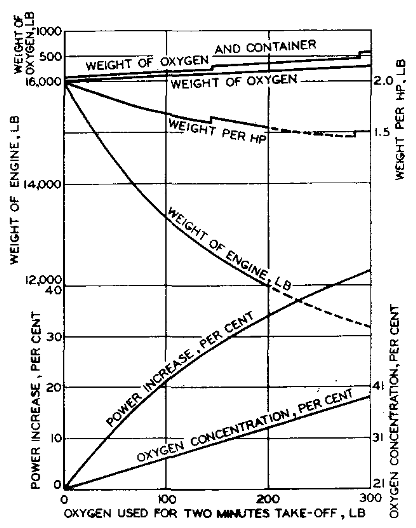 |
Oxygen addition may be used for starting diesel engines. The raising of the oxygen concentration from the normal 21 per cent to 45 per cent was found to be equivalent to a raise of approximately 10 cetane numbers as far as starting is concerned.
Five per cent increase in oxygen concentration eliminated exhaust smoke completely.
Table 1
| Normal horsepower | 6000 |
| Take-off horsepower | 8000 |
| Normal fuel consumption | 0.4 lb per hp-hr, or 53.5 lb per min |
| Normal air consumption | 900 lb per min |
| Normal oxygen consumption, 21 per cent oxygen concentration | 189 lb per min |
| Boosted oxygen consumption, 32 per cent oxygen concentration | 289 lb per min |
| Oxygen to be supplied | 100 lb per min |
| Weight of 8000-hp engine | 16,000 lb |
| Weight of boosted 6000-hp engine | 12,000 lb |
| Weight of oxygen for 2-min boost | 200 lb |
| Weight of container for 29 lb of liquid oxygen | 150 lb |
| Net weight saving by oxygen boost | 3650 lb |
| Weight per horsepower, nonboosted engine | 2 lb |
| Weight per horsepower, boosted engine | 1.54 lb |
Footnotes:
[2] Letter, Hermann I. A. Dorner to National Air Museum, March 3, 1962.
[5] Aeronautics (October 1929), vol. 5, no. 4, p. 32.
[6] The Packard Diesel Aircraft Engine—A New Chapter in Transportation Progress (Detroit: Packard Motor Car Co., 1930), p. 5.
[7] A memorial to Woolson who was killed in the crash of a Packard diesel-powered Verville “Air Sedan” on April 23, 1930.
[8] Packard Inner Circle (April 18, 1932), vol. 17, no. 6, p. 1.
[9] Aero Digest (February 1932), vol. 20, no. 2, p. 54.
[10] Letter, Richard Totten to National Air Museum, January 28, 1964.
[11] Instruction Book for the Packard-Diesel Aircraft Engine (Detroit: Packard Motor Car Company, 1931), p. 3.
[12] S.A.E. Journal (April 1930), vol. 24, no. 4, pp. 431 and 432.
[13] Letter, Richard Totten to National Air Museum, January 28, 1964.
[14] Letter, Hermann I. A. Dorner to National Air Museum, December 16, 1961.
[15] The National Aeronautic Magazine (April 1932), vol. 10, no. 4. p. 18.
[16] Aviation (May 1931), vol. 30, no. 5, p. 281.
[17] The Packard Diesel Aircraft Engine, p. 5.
[18] Instruction Book for the Packard-Diesel Aircraft Engine, p. 3.
[19] “Test of Packard-Diesel radial air-cooled engine,” Navy Department, Bureau of Aeronautics, Report AEL-335, July 13, 1931, Bu. Aer. Proj. 2265.
[20] Aviation (May 1931), vol. 30, no. 5, p. 281.
[21] Letter, Clarence H. Wiegman to National Air Museum, November 1, 1961.
[22] Letter, Dorner to National Air Museum, January 15, 1962.
[23] Letter, Hugo T. Byttebier to National Air Museum, October 20, 1961.
[24] Letter, Clarence D. Chamberlin to National Air Museum, February 8, 1964.
[25] Ruth Nichols, Wings For Life (Philadelphia and New York: J. B. Lippincott Co., 1957), p. 205.
[26] Letter, Richard Totten to National Air Museum, January 28, 1964.
[27] Letter, Richard Totten to National Air Museum, January 28, 1961.
[28] Aero Digest (February 1931), vol. 18, no. 2, p. 58.
[29] “50-Hour Test of Packard Diesel Aircraft Engine,” Packard Motor Car Company, Detroit, Michigan, serial no. 426, test no. 234-73, February 19, 1930.
[30] Blower in this sense refers to a low-pressure air pump (supercharger) designed to increase cylinder scavenging efficiency by blowing out exhaust gasses. In doing this it also increases somewhat the amount of fresh air introduced into the cylinders. Woolson invented a 2-stroke cycle blown engine; the patent was issued in 1932 (patent 1853714) with rights assigned to the Packard Motor Car Company. (Woolson himself died in 1930.)
[31] A 2-stroke cycle engine completes 360° of crankshaft rotation in what it takes a 4-stroke cycle engine 720° to accomplish. A 3-cylinder two-stroke cycle engine therefore has the same capacity to do work as a 6-cylinder four-stroke cycle engine. For this reason the former type of engine is both more compact and lighter than the latter type.
The above advantages, plus the increased efficiency of the blown 2-cycle diesel, are discussed in Flight—The Aeronautical Engineer Supplement (December 26, 1940), vol. 19, no. 11, pp. 545 and 552.
[32] Packard advertisement—Aero Digest (June 1930), vol. 16, no. 6, p. 23.
[33] Aviation (March 15, 1930), vol. 28, no. 11, p. 531.
[34] The National Aeronautic Magazine (April 1932), vol. 10, no. 4., p. 18.
[36] See Woolson’s patent 1794047, issued in 1931 and assigned to the Packard Motor Car Company. “An object of my invention is to automatically regulate the compression ratio in an engine inversely to the speed....” See also his patent 1891321, issued in 1932 and assigned to the Packard Motor Car Company. It describes a similar but nonautomatic system. Woolson therefore fully realized the disadvantages of the high cylinder pressures his engine developed at high rpm’s.
[37] Letter, Clarence H. Wiegman to National Air Museum, November 1, 1961.
[38] Ibid.
[39] Major George E. A. Hallet, U.S. Air Service, former director of engineering division, McCook Field, Dayton, Ohio.
[40] “Test of Packard-Diesel radial air-cooled engine,” Navy Department, Bureau of Aeronautics, Report AEL-335, July 13, 1931, BuAer Proj. 2265.
[41] Aviation Week and Space Technology (February 19, 1962), vol. 76, no. 8, p. 101.
[42] Aeronautics (October 1929), vol. 5, no. 4, p. 31.
[43] Letter, Richard Totten to National Air Museum, January 28, 1964.
[44] According to Frederic E. Hatch of the National Air Museum, it is possible that the engine failed because the fuel injectors became clogged. He notes that the airplane refueled at several fishing ports, and therefore must have used diesel oil set aside for fishing boats. This oil was generally quite dirty. As a result it was routine for the fishermen to have to clean engine oil filters frequently enroute. The oil filters of the Packard diesel could not be cleaned in flight.
Transcriber’s Notes:
Other than the corrections noted by hover information in the text, printer’s inconsistencies in spelling, punctuation, and hyphenation usage have been retained.
End of the Project Gutenberg EBook of The First Airplane Diesel Engine:
Packard Model DR-980 of 1928, by Robert B. Meyer

*** END OF THIS PROJECT GUTENBERG EBOOK FIRST AIRPLANE DIESEL ENGINE ***

***** This file should be named 31023-h.htm or 31023-h.zip *****
This and all associated files of various formats will be found in:
        https://www.gutenberg.org/3/1/0/2/31023/

Produced by Chris Curnow, Joseph Cooper, Stephanie Eason,
and the Online Distributed Proofreading Team at
https://www.pgdp.net.


Updated editions will replace the previous one--the old editions
will be renamed.

Creating the works from public domain print editions means that no
one owns a United States copyright in these works, so the Foundation
(and you!) can copy and distribute it in the United States without
permission and without paying copyright royalties.  Special rules,
set forth in the General Terms of Use part of this license, apply to
copying and distributing Project Gutenberg-tm electronic works to
protect the PROJECT GUTENBERG-tm concept and trademark.  Project
Gutenberg is a registered trademark, and may not be used if you
charge for the eBooks, unless you receive specific permission.  If you
do not charge anything for copies of this eBook, complying with the
rules is very easy.  You may use this eBook for nearly any purpose
such as creation of derivative works, reports, performances and
research.  They may be modified and printed and given away--you may do
practically ANYTHING with public domain eBooks.  Redistribution is
subject to the trademark license, especially commercial
redistribution.


*** START: FULL LICENSE ***

THE FULL PROJECT GUTENBERG LICENSE
PLEASE READ THIS BEFORE YOU DISTRIBUTE OR USE THIS WORK

To protect the Project Gutenberg-tm mission of promoting the free
distribution of electronic works, by using or distributing this work
(or any other work associated in any way with the phrase "Project
Gutenberg"), you agree to comply with all the terms of the Full Project
Gutenberg-tm License (available with this file or online at
https://gutenberg.org/license).


Section 1.  General Terms of Use and Redistributing Project Gutenberg-tm
electronic works

1.A.  By reading or using any part of this Project Gutenberg-tm
electronic work, you indicate that you have read, understand, agree to
and accept all the terms of this license and intellectual property
(trademark/copyright) agreement.  If you do not agree to abide by all
the terms of this agreement, you must cease using and return or destroy
all copies of Project Gutenberg-tm electronic works in your possession.
If you paid a fee for obtaining a copy of or access to a Project
Gutenberg-tm electronic work and you do not agree to be bound by the
terms of this agreement, you may obtain a refund from the person or
entity to whom you paid the fee as set forth in paragraph 1.E.8.

1.B.  "Project Gutenberg" is a registered trademark.  It may only be
used on or associated in any way with an electronic work by people who
agree to be bound by the terms of this agreement.  There are a few
things that you can do with most Project Gutenberg-tm electronic works
even without complying with the full terms of this agreement.  See
paragraph 1.C below.  There are a lot of things you can do with Project
Gutenberg-tm electronic works if you follow the terms of this agreement
and help preserve free future access to Project Gutenberg-tm electronic
works.  See paragraph 1.E below.

1.C.  The Project Gutenberg Literary Archive Foundation ("the Foundation"
or PGLAF), owns a compilation copyright in the collection of Project
Gutenberg-tm electronic works.  Nearly all the individual works in the
collection are in the public domain in the United States.  If an
individual work is in the public domain in the United States and you are
located in the United States, we do not claim a right to prevent you from
copying, distributing, performing, displaying or creating derivative
works based on the work as long as all references to Project Gutenberg
are removed.  Of course, we hope that you will support the Project
Gutenberg-tm mission of promoting free access to electronic works by
freely sharing Project Gutenberg-tm works in compliance with the terms of
this agreement for keeping the Project Gutenberg-tm name associated with
the work.  You can easily comply with the terms of this agreement by
keeping this work in the same format with its attached full Project
Gutenberg-tm License when you share it without charge with others.

1.D.  The copyright laws of the place where you are located also govern
what you can do with this work.  Copyright laws in most countries are in
a constant state of change.  If you are outside the United States, check
the laws of your country in addition to the terms of this agreement
before downloading, copying, displaying, performing, distributing or
creating derivative works based on this work or any other Project
Gutenberg-tm work.  The Foundation makes no representations concerning
the copyright status of any work in any country outside the United
States.

1.E.  Unless you have removed all references to Project Gutenberg:

1.E.1.  The following sentence, with active links to, or other immediate
access to, the full Project Gutenberg-tm License must appear prominently
whenever any copy of a Project Gutenberg-tm work (any work on which the
phrase "Project Gutenberg" appears, or with which the phrase "Project
Gutenberg" is associated) is accessed, displayed, performed, viewed,
copied or distributed:

This eBook is for the use of anyone anywhere at no cost and with
almost no restrictions whatsoever.  You may copy it, give it away or
re-use it under the terms of the Project Gutenberg License included
with this eBook or online at www.gutenberg.org

1.E.2.  If an individual Project Gutenberg-tm electronic work is derived
from the public domain (does not contain a notice indicating that it is
posted with permission of the copyright holder), the work can be copied
and distributed to anyone in the United States without paying any fees
or charges.  If you are redistributing or providing access to a work
with the phrase "Project Gutenberg" associated with or appearing on the
work, you must comply either with the requirements of paragraphs 1.E.1
through 1.E.7 or obtain permission for the use of the work and the
Project Gutenberg-tm trademark as set forth in paragraphs 1.E.8 or
1.E.9.

1.E.3.  If an individual Project Gutenberg-tm electronic work is posted
with the permission of the copyright holder, your use and distribution
must comply with both paragraphs 1.E.1 through 1.E.7 and any additional
terms imposed by the copyright holder.  Additional terms will be linked
to the Project Gutenberg-tm License for all works posted with the
permission of the copyright holder found at the beginning of this work.

1.E.4.  Do not unlink or detach or remove the full Project Gutenberg-tm
License terms from this work, or any files containing a part of this
work or any other work associated with Project Gutenberg-tm.

1.E.5.  Do not copy, display, perform, distribute or redistribute this
electronic work, or any part of this electronic work, without
prominently displaying the sentence set forth in paragraph 1.E.1 with
active links or immediate access to the full terms of the Project
Gutenberg-tm License.

1.E.6.  You may convert to and distribute this work in any binary,
compressed, marked up, nonproprietary or proprietary form, including any
word processing or hypertext form.  However, if you provide access to or
distribute copies of a Project Gutenberg-tm work in a format other than
"Plain Vanilla ASCII" or other format used in the official version
posted on the official Project Gutenberg-tm web site (www.gutenberg.org),
you must, at no additional cost, fee or expense to the user, provide a
copy, a means of exporting a copy, or a means of obtaining a copy upon
request, of the work in its original "Plain Vanilla ASCII" or other
form.  Any alternate format must include the full Project Gutenberg-tm
License as specified in paragraph 1.E.1.

1.E.7.  Do not charge a fee for access to, viewing, displaying,
performing, copying or distributing any Project Gutenberg-tm works
unless you comply with paragraph 1.E.8 or 1.E.9.

1.E.8.  You may charge a reasonable fee for copies of or providing
access to or distributing Project Gutenberg-tm electronic works provided
that

- You pay a royalty fee of 20% of the gross profits you derive from
     the use of Project Gutenberg-tm works calculated using the method
     you already use to calculate your applicable taxes.  The fee is
     owed to the owner of the Project Gutenberg-tm trademark, but he
     has agreed to donate royalties under this paragraph to the
     Project Gutenberg Literary Archive Foundation.  Royalty payments
     must be paid within 60 days following each date on which you
     prepare (or are legally required to prepare) your periodic tax
     returns.  Royalty payments should be clearly marked as such and
     sent to the Project Gutenberg Literary Archive Foundation at the
     address specified in Section 4, "Information about donations to
     the Project Gutenberg Literary Archive Foundation."

- You provide a full refund of any money paid by a user who notifies
     you in writing (or by e-mail) within 30 days of receipt that s/he
     does not agree to the terms of the full Project Gutenberg-tm
     License.  You must require such a user to return or
     destroy all copies of the works possessed in a physical medium
     and discontinue all use of and all access to other copies of
     Project Gutenberg-tm works.

- You provide, in accordance with paragraph 1.F.3, a full refund of any
     money paid for a work or a replacement copy, if a defect in the
     electronic work is discovered and reported to you within 90 days
     of receipt of the work.

- You comply with all other terms of this agreement for free
     distribution of Project Gutenberg-tm works.

1.E.9.  If you wish to charge a fee or distribute a Project Gutenberg-tm
electronic work or group of works on different terms than are set
forth in this agreement, you must obtain permission in writing from
both the Project Gutenberg Literary Archive Foundation and Michael
Hart, the owner of the Project Gutenberg-tm trademark.  Contact the
Foundation as set forth in Section 3 below.

1.F.

1.F.1.  Project Gutenberg volunteers and employees expend considerable
effort to identify, do copyright research on, transcribe and proofread
public domain works in creating the Project Gutenberg-tm
collection.  Despite these efforts, Project Gutenberg-tm electronic
works, and the medium on which they may be stored, may contain
"Defects," such as, but not limited to, incomplete, inaccurate or
corrupt data, transcription errors, a copyright or other intellectual
property infringement, a defective or damaged disk or other medium, a
computer virus, or computer codes that damage or cannot be read by
your equipment.

1.F.2.  LIMITED WARRANTY, DISCLAIMER OF DAMAGES - Except for the "Right
of Replacement or Refund" described in paragraph 1.F.3, the Project
Gutenberg Literary Archive Foundation, the owner of the Project
Gutenberg-tm trademark, and any other party distributing a Project
Gutenberg-tm electronic work under this agreement, disclaim all
liability to you for damages, costs and expenses, including legal
fees.  YOU AGREE THAT YOU HAVE NO REMEDIES FOR NEGLIGENCE, STRICT
LIABILITY, BREACH OF WARRANTY OR BREACH OF CONTRACT EXCEPT THOSE
PROVIDED IN PARAGRAPH F3.  YOU AGREE THAT THE FOUNDATION, THE
TRADEMARK OWNER, AND ANY DISTRIBUTOR UNDER THIS AGREEMENT WILL NOT BE
LIABLE TO YOU FOR ACTUAL, DIRECT, INDIRECT, CONSEQUENTIAL, PUNITIVE OR
INCIDENTAL DAMAGES EVEN IF YOU GIVE NOTICE OF THE POSSIBILITY OF SUCH
DAMAGE.

1.F.3.  LIMITED RIGHT OF REPLACEMENT OR REFUND - If you discover a
defect in this electronic work within 90 days of receiving it, you can
receive a refund of the money (if any) you paid for it by sending a
written explanation to the person you received the work from.  If you
received the work on a physical medium, you must return the medium with
your written explanation.  The person or entity that provided you with
the defective work may elect to provide a replacement copy in lieu of a
refund.  If you received the work electronically, the person or entity
providing it to you may choose to give you a second opportunity to
receive the work electronically in lieu of a refund.  If the second copy
is also defective, you may demand a refund in writing without further
opportunities to fix the problem.

1.F.4.  Except for the limited right of replacement or refund set forth
in paragraph 1.F.3, this work is provided to you 'AS-IS' WITH NO OTHER
WARRANTIES OF ANY KIND, EXPRESS OR IMPLIED, INCLUDING BUT NOT LIMITED TO
WARRANTIES OF MERCHANTIBILITY OR FITNESS FOR ANY PURPOSE.

1.F.5.  Some states do not allow disclaimers of certain implied
warranties or the exclusion or limitation of certain types of damages.
If any disclaimer or limitation set forth in this agreement violates the
law of the state applicable to this agreement, the agreement shall be
interpreted to make the maximum disclaimer or limitation permitted by
the applicable state law.  The invalidity or unenforceability of any
provision of this agreement shall not void the remaining provisions.

1.F.6.  INDEMNITY - You agree to indemnify and hold the Foundation, the
trademark owner, any agent or employee of the Foundation, anyone
providing copies of Project Gutenberg-tm electronic works in accordance
with this agreement, and any volunteers associated with the production,
promotion and distribution of Project Gutenberg-tm electronic works,
harmless from all liability, costs and expenses, including legal fees,
that arise directly or indirectly from any of the following which you do
or cause to occur: (a) distribution of this or any Project Gutenberg-tm
work, (b) alteration, modification, or additions or deletions to any
Project Gutenberg-tm work, and (c) any Defect you cause.


Section  2.  Information about the Mission of Project Gutenberg-tm

Project Gutenberg-tm is synonymous with the free distribution of
electronic works in formats readable by the widest variety of computers
including obsolete, old, middle-aged and new computers.  It exists
because of the efforts of hundreds of volunteers and donations from
people in all walks of life.

Volunteers and financial support to provide volunteers with the
assistance they need are critical to reaching Project Gutenberg-tm's
goals and ensuring that the Project Gutenberg-tm collection will
remain freely available for generations to come.  In 2001, the Project
Gutenberg Literary Archive Foundation was created to provide a secure
and permanent future for Project Gutenberg-tm and future generations.
To learn more about the Project Gutenberg Literary Archive Foundation
and how your efforts and donations can help, see Sections 3 and 4
and the Foundation web page at https://www.pglaf.org.


Section 3.  Information about the Project Gutenberg Literary Archive
Foundation

The Project Gutenberg Literary Archive Foundation is a non profit
501(c)(3) educational corporation organized under the laws of the
state of Mississippi and granted tax exempt status by the Internal
Revenue Service.  The Foundation's EIN or federal tax identification
number is 64-6221541.  Its 501(c)(3) letter is posted at
https://pglaf.org/fundraising.  Contributions to the Project Gutenberg
Literary Archive Foundation are tax deductible to the full extent
permitted by U.S. federal laws and your state's laws.

The Foundation's principal office is located at 4557 Melan Dr. S.
Fairbanks, AK, 99712., but its volunteers and employees are scattered
throughout numerous locations.  Its business office is located at
809 North 1500 West, Salt Lake City, UT 84116, (801) 596-1887, email
business@pglaf.org.  Email contact links and up to date contact
information can be found at the Foundation's web site and official
page at https://pglaf.org

For additional contact information:
     Dr. Gregory B. Newby
     Chief Executive and Director
     gbnewby@pglaf.org


Section 4.  Information about Donations to the Project Gutenberg
Literary Archive Foundation

Project Gutenberg-tm depends upon and cannot survive without wide
spread public support and donations to carry out its mission of
increasing the number of public domain and licensed works that can be
freely distributed in machine readable form accessible by the widest
array of equipment including outdated equipment.  Many small donations
($1 to $5,000) are particularly important to maintaining tax exempt
status with the IRS.

The Foundation is committed to complying with the laws regulating
charities and charitable donations in all 50 states of the United
States.  Compliance requirements are not uniform and it takes a
considerable effort, much paperwork and many fees to meet and keep up
with these requirements.  We do not solicit donations in locations
where we have not received written confirmation of compliance.  To
SEND DONATIONS or determine the status of compliance for any
particular state visit https://pglaf.org

While we cannot and do not solicit contributions from states where we
have not met the solicitation requirements, we know of no prohibition
against accepting unsolicited donations from donors in such states who
approach us with offers to donate.

International donations are gratefully accepted, but we cannot make
any statements concerning tax treatment of donations received from
outside the United States.  U.S. laws alone swamp our small staff.

Please check the Project Gutenberg Web pages for current donation
methods and addresses.  Donations are accepted in a number of other
ways including including checks, online payments and credit card
donations.  To donate, please visit: https://pglaf.org/donate


Section 5.  General Information About Project Gutenberg-tm electronic
works.

Professor Michael S. Hart was the originator of the Project Gutenberg-tm
concept of a library of electronic works that could be freely shared
with anyone.  For thirty years, he produced and distributed Project
Gutenberg-tm eBooks with only a loose network of volunteer support.


Project Gutenberg-tm eBooks are often created from several printed
editions, all of which are confirmed as Public Domain in the U.S.
unless a copyright notice is included.  Thus, we do not necessarily
keep eBooks in compliance with any particular paper edition.


Most people start at our Web site which has the main PG search facility:

     https://www.gutenberg.org

This Web site includes information about Project Gutenberg-tm,
including how to make donations to the Project Gutenberg Literary
Archive Foundation, how to help produce our new eBooks, and how to
subscribe to our email newsletter to hear about new eBooks.