The Project Gutenberg EBook of The 'Pioneer': Light Passenger Locomotive
of 1851, by John H. White

This eBook is for the use of anyone anywhere at no cost and with
almost no restrictions whatsoever.  You may copy it, give it away or
re-use it under the terms of the Project Gutenberg License included
with this eBook or online at www.gutenberg.org


Title: The 'Pioneer': Light Passenger Locomotive of 1851
       United States Bulletin 240, Contributions from the Museum
              of History and Technology, paper 42, 1964

Author: John H. White

Release Date: February 23, 2009 [EBook #28160]

Language: English

Character set encoding: ISO-8859-1

*** START OF THIS PROJECT GUTENBERG EBOOK LIGHT PASSENGER LOCOMOTIVE ***


Produced by Chris Curnow, Louise Pattison, Joseph Cooper
and the Online Distributed Proofreading Team at
http://www.pgdp.net
This is Paper 42 from the Smithsonian Institution United States National Museum Bulletin 240, comprising Papers 34-44, which will also be available as a complete e-book.
The front material, introduction and relevant index entries from the Bulletin are included in each single-paper e-book.
Underlined Figure numbers link to high resolution copies of selected images.
Corrections to typographical errors are underlined like this. Mouse over to view the original text.
SMITHSONIAN PRESS
MUSEUM OF HISTORY AND TECHNOLOGY
Contributions
From the
Museum
of History and
Technology
Papers 34-44
On Science and Technology
SMITHSONIAN INSTITUTION · WASHINGTON, D.C. 1966
Publications of the United States National Museum
The scholarly and scientific publications of the United States National Museum include two series, Proceedings of the United States National Museum and United States National Museum Bulletin.
In these series, the Museum publishes original articles and monographs dealing with the collections and work of its constituent museums—The Museum of Natural History and the Museum of History and Technology—setting forth newly acquired facts in the fields of anthropology, biology, history, geology, and technology. Copies of each publication are distributed to libraries, to cultural and scientific organizations, and to specialists and others interested in the different subjects.
The Proceedings, begun in 1878, are intended for the publication, in separate form, of shorter papers from the Museum of Natural History. These are gathered in volumes, octavo in size, with the publication date of each paper recorded in the table of contents of the volume.
In the Bulletin series, the first of which was issued in 1875, appear longer, separate publications consisting of monographs (occasionally in several parts) and volumes in which are collected works on related subjects. Bulletins are either octavo or quarto in size, depending on the needs of the presentation. Since 1902 papers relating to the botanical collections of the Museum of Natural History have been published in the Bulletin series under the heading Contributions from the United States National Herbarium, and since 1959, in Bulletins titled “Contributions from the Museum of History and Technology,” have been gathered shorter papers relating to the collections and research of that Museum.
The present collection of Contributions, Papers 34-44, comprises Bulletin 240. Each of these papers has been previously published in separate form. The year of publication is shown on the last page of each paper.
Frank A. Taylor
Director, United States National Museum
John H. White
THE CUMBERLAND VALLEY RAILROAD 244
SERVICE HISTORY OF THE “PIONEER” 249
MECHANICAL DESCRIPTION OF THE “PIONEER” 251

Figure 1.—The “Pioneer,” built in 1851, shown here as renovated and exhibited in the Museum of History and Technology, 1964. In 1960 the locomotive was given to the Smithsonian Institution by the Pennsylvania Railroad through John S. Fair, Jr. (Smithsonian photo 63344B.)
[Pg 243]John H. White
In the mid-nineteenth century there was a renewed interest in the light, single-axle locomotives which were proving so very successful for passenger traffic. These engines were built in limited number by nearly every well-known maker, and among the few remaining is the 6-wheel “Pioneer,” on display in the Museum of History and Technology, Smithsonian Institution. This locomotive is a true representation of a light passenger locomotive of 1851 and a historic relic of the mid-nineteenth century.
The Author: John H. White is associate curator of transportation in the Smithsonian Institution’s Museum of History and Technology.
The “Pioneer” is an unusual locomotive and on first inspection would seem to be imperfect for service on an American railroad of the 1850’s. This locomotive has only one pair of driving wheels and no truck, an arrangement which marks it as very different from the highly successful standard 8-wheel engine of this period. All six wheels of the Pioneer are rigidly attached to the frame. It is only half the size of an 8-wheel engine of 1851 and about the same size of the 4—2—0 so common in this country some 20 years earlier. Its general arrangement is that of the rigid English locomotive which had, years earlier, proven unsuitable for use on U.S. railroads.
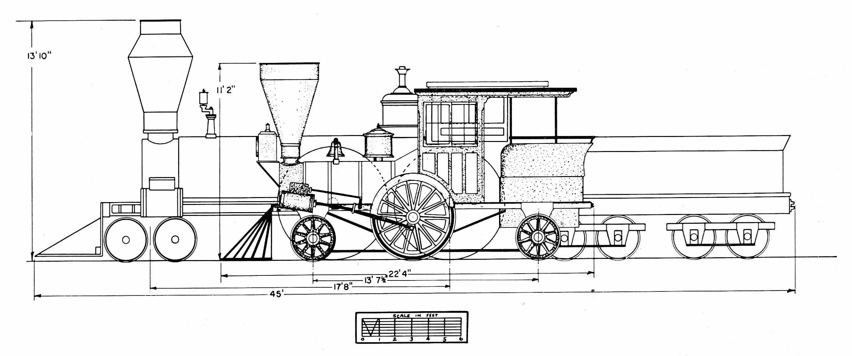
These objections are more apparent than real, for the Pioneer, and other engines of the same design, proved eminently successful when used in the service for which they were built, that of light passenger traffic. The Pioneer’s rigid wheelbase is no problem, for when it is compared to that of an 8-wheel engine it is found to be about four feet less; and its small size is no problem when we realize it was not intended for heavy service. Figure 2, a diagram, is a comparison of the Pioneer and a standard 8-wheel locomotive.
Since the service life of the Pioneer was spent on the Cumberland Valley Railroad, a brief account of that line is necessary to an understanding of the service history of this locomotive.
The Cumberland Valley Railroad (C.V.R.R.) was chartered on April 2, 1831, to connect the Susquehanna and Potomac Rivers by a railroad through the Cumberland Valley in south-central Pennsylvania. The Cumberland Valley, with its rich farmland and iron-ore deposits, was a natural north-south route long used as a portage between these two rivers. Construction began in 1836, and because of the level valley some 52 miles of line was completed between Harrisburg and Chambersburg by November 16, 1837. In 1860, by way of the Franklin Railroad, the line extended to Hagerstown, Maryland. It was not until 1871 that the Cumberland Valley Railroad reached its projected southern terminus, the Potomac River, by extending to Powells Bend, Maryland. Winchester, Virginia, was entered in 1890 giving the Cumberland Valley Railroad about 165 miles of line. The railroad which had become associated with the Pennsylvania Railroad in 1859, was merged with that company in 1919.
By 1849 the Cumberland Valley Railroad was in poor condition; the strap-rail track was worn out and new locomotives were needed. Captain Daniel Tyler was hired to supervise rebuilding the line with T-rail, and easy grades and curves. Tyler recommended that a young friend of his, Alba F. Smith, be put in charge of modernizing and acquiring new equipment. Smith recommended to the railroad’s Board of Managers on June 25, 1851, that “much lighter engines than those now in use may be substituted for the passenger transportation and thereby effect a great saving both in point of fuel and road repairs....”[1] Smith may well have gone on to explain that the road was operating 3- and 4-car passenger trains with a locomotive weighing about 20 tons; the total weight was about 75 tons, equalling the uneconomical deadweight of 1200 pounds per passenger. Since speed was not an important consideration (30 mph being a good average), the use of lighter engines would improve the deadweight-to-passenger ratio and would not result in a slower schedule.
The Board of Managers agreed with Smith’s recommendations and instructed him “... to examine the two locomotives lately built by Mr. Wilmarth and now in the [protection?] of Captain Tyler at Norwich and if in his judgment they are adequate to our wants ... have them forwarded to the road.”[2] Smith inspected the locomotives not long after this resolution was passed, for they were on the road by the time he made the following report[3] to the Board on September 24, 1851:
In accordance with a resolution passed at the last meeting of your body relative to the small engines built by Mr. Wilmarth I proceeded to Norwich to make trial of their capacity—fitness or suitability to the Passenger transportation of our Road—and after as thorough a trial as circumstances would admit (being on another Road than our own) I became satisfied that with some necessary improvements which would not be expensive (and are now being made at our shop)[Pg 245] the engines would do the business of our Road not only in a manner satisfactory in point of speed and certainty but with greater ultimate economy in Expenses than has before been practised in this Country.

Figure 2.—Diagram comparing the Pioneer (shaded drawing) with the Columbia, a standard 8-wheel engine of 1851. (Drawing by J. H. White.)
|
Columbia |
Pioneer |
After making the above trial of the Engines—I stated to your Hon. President the result of the trial—with my opinion of their Capacity to carry our passenger trains at the speed required which was decidedly in favor of the ability of the Engines. He accordingly agreed that the Engines should at once be forwarded to the Road in compliance with the Resolution of your Board. I immediately ordered the Engines shipped at the most favorable rates. They came to our Road safely in the Condition in which they were shipped. One of the Engines has been placed on the Road and I believe performed in such a manner as to convince all who are able to judge of this ability to perform—although the maximum duty of the Engines was not performed on account of some original defects which are now being remedied as I before stated.
Within ten days the Engine will be able to run regularly with a train on the Road where in shall be enabled to judge correctly of their merits.
An accident occurred during the trial of the Small Engine at Norwich which caused a damage of about $300 in which condition the Engine came here and is now being repaired—the cost of which will be presented to your Board hereafter. As to the fault or blame of parties connected with the accident as also the question of responsibility for Repairs are questions for your disposal. I therefore leave the matter until further called upon.
The Expenses necessarily incurred by the trial of the Engines and also the Expenses of transporting the same are not included in the Statement herewith presented, the whole amount of which will not probably exceed $400.00.
These two locomotives became the Cumberland Valley Railroad’s Pioneer (number 13) and Jenny Lind (number 14). While Smith notes that one of the engines was damaged during the inspection trials, Joseph Winters, an employee of the Cumberland Valley who claimed he was accompanying the engine enroute to Chambersburg at the time of their delivery, later recalled that both engines were damaged in transit.[4] According to Winters a train ran into the rear of the Jenny Lind, damaging both it and the Pioneer, the accident occurring near Middletown, Pennsylvania. The Jenny Lind was repaired at Harrisburg but the Pioneer, less seriously damaged, was taken for repairs to the main shops of the Cumberland Valley road at Chambersburg.

Figure 3.—“Pioneer,” about 1901, showing the sandbox and large headlamp. Note the lamp on the cab roof, now used as the headlight. (Smithsonian photo 49272.)
While there seems little question that these locomotives were not built as a direct order for the Cumberland Valley Railroad, an article[5] appearing in the Railroad Advocate in 1855 credits their design to Smith. The article speaks of a 2—2—4 built for the Macon and Western Railroad and says in part:
This engine is designed and built very generally upon the ideas, embodied in some small tank engines designed by A. F. Smith, Esq., for the Cumberland Valley road. Mr. Smith is a strong advocate of light engines, and his novel style and proportions of engines, as built for him a few years since, by Seth Wilmarth, at Boston, are known to some of our readers. Without knowing all the circumstances under which these engines are worked on the Cumberland Valley road, we should not venture to repeat all that we have heard of their performances, it is enough to say that they are said to do more, in proportion to their weight, than any other engines now in use.
The author believes that the Railroad Advocate’s claim of Smith’s design of the Pioneer has been confused with his design of the Utility (figs. 6, 7). Smith designed this compensating-lever engine to haul trains over the C.V.R.R. bridge at Harrisburg. It was built by Wilmarth in 1854.

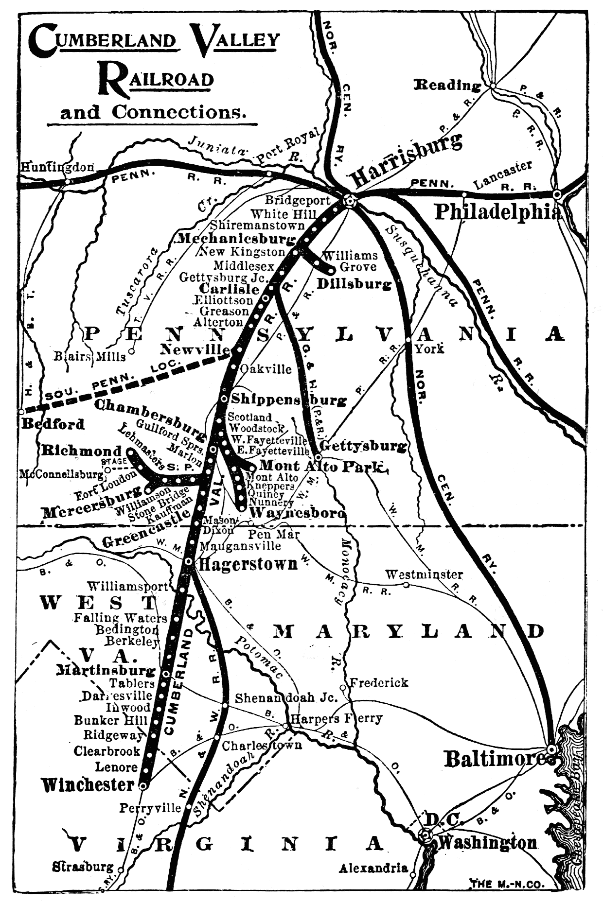
Figure 4.—Map of the Cumberland Valley Railroad as it appeared in 1919.

Figure 5.—An early broadside of the Cumberland Valley Railroad.
According to statements of Smith and the Board of Managers quoted on page 244, the Pioneer and the Jenny Lind were not new when purchased from their maker, Seth Wilmarth. Although of recent manufacture, previous to June 1851, they were apparently doing service on a road in Norwich, Connecticut. It[Pg 247] should be mentioned that both Smith and Tyler were formerly associated with the Norwich and Worcester Railroad and they probably learned of these two engines through this former association. It is possible that the engines were purchased from Wilmarth by the Cumberland Valley road, which had bought several other locomotives from Wilmarth in previous years. It was the practice of at least one other New England engine builder, the Taunton Locomotive Works, to manufacture engines on the speculation that a buyer would be found; if no immediate buyers appeared the engine was leased to a local road until a sale was made.[6]
Regarding the Jenny Lind and Pioneer, Smith reported[7] to the Board of Managers at their meeting of March 17, 1852:
The small tank engines which were purchased last year ... and which I spoke in a former report as undergoing at that time some necessary improvements have since that time been fairly tested as to their capacity to run our passenger trains and proved to be equal to the duty.
The improvements proposed to be made have been completed only on one engine [Jenny Lind] which is now running regularly with passenger trains—the cost of repairs and improvements on this engine (this being the one accidentally broken on the trial) amounted to $476.51. The other engine is now in the shop, not yet ready for service but will be at an early day.

Figure 6.—The “Utility” as rebuilt to an 8-wheel engine, about 1863 or 1864. It was purchased by the Carlisle Manufacturing Co. in 1882 and was last used in 1896. (Smithsonian photo 36716F.)

Figure 7.—The “Utility,” designed by Smith A. F. and constructed by Seth Wilmarth in 1854, was built to haul trains across the bridge at Harrisburg, Pa.

Figure 8.—The earliest known illustration of the Pioneer, drawn by A. S. Hull, master mechanic of the Cumberland Valley Railroad in 1876. It depicts the engine as it appeared in 1871. (Courtesy of Paul Westhaeffer.)
The Pioneer and Jenny Lind achieved such success in action that the president of the road, Frederick Watts, commented on their performance in the annual report of the Cumberland Valley Railroad for 1851. Watts stated that since their passenger trains were rarely more than a baggage car and two coaches, the light locomotives “... have been found to be admirably adapted to our business.” The Cumberland Valley Railroad, therefore, added two more locomotives of similar design in the next few years. These engines were the Boston and the Enterprise, also built by Wilmarth in 1854-1855.
Watts reported the Pioneer and Jenny Lind cost $7,642. A standard 8-wheel engine cost about $6,500 to $8,000 each during this period. In recent years, the Pennsylvania Railroad has stated the Pioneer cost $6,200 in gold, but is unable to give the source for this information. The author can discount this statement for it does not seem reasonable that a light, cheap engine of the pattern of the Pioneer could cost as much as a machine nearly twice its size.

Figure 9.—Annual pass of the Cumberland Valley Railroad issued in 1863.

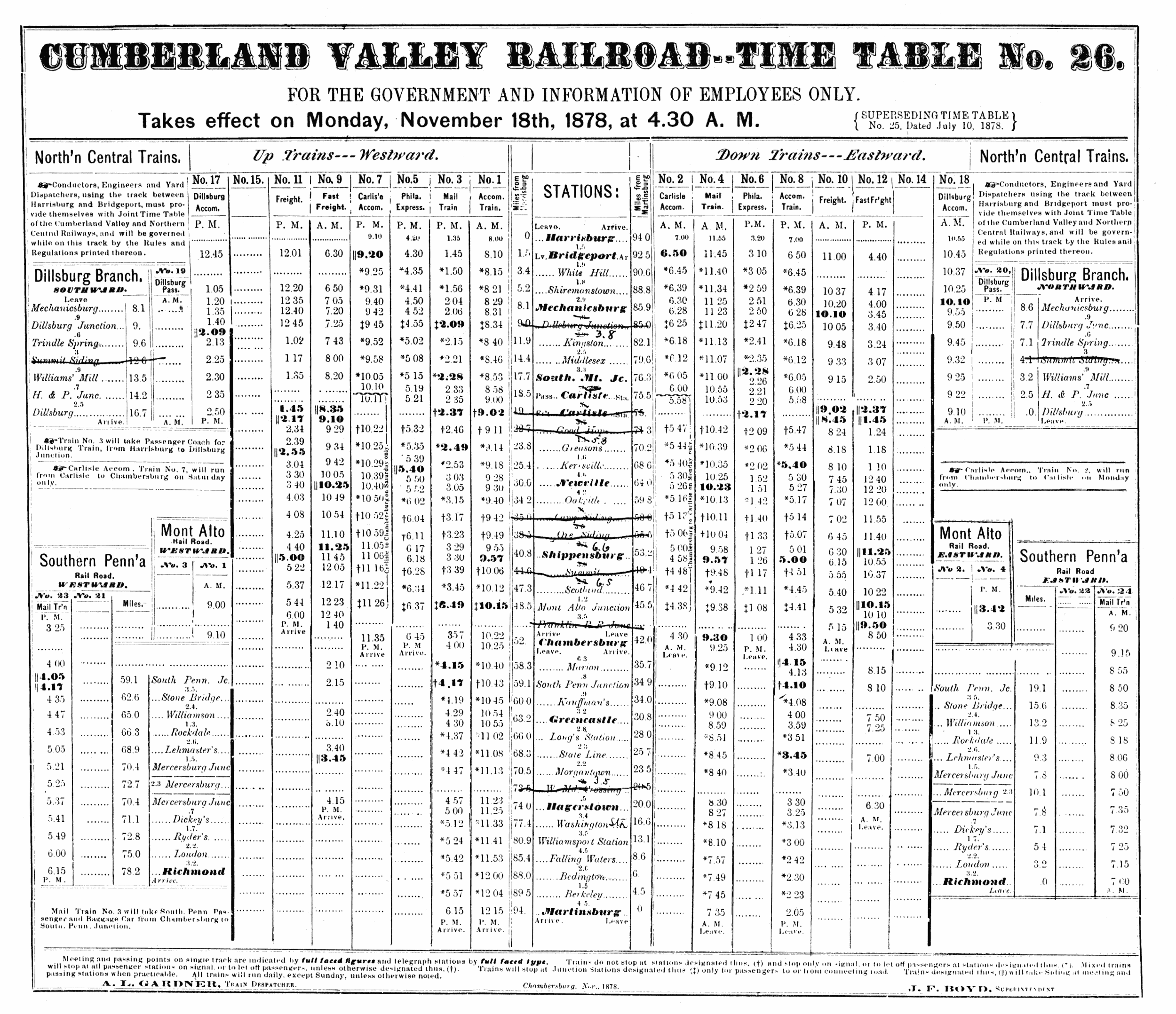
Figure 10.—Timetable of the Cumberland Valley Railroad for 1878.
After being put in service, the Pioneer continued to perform well and was credited as able to move a 4-car passenger train along smartly at 40 mph.[8] This tranquility was shattered in October 1862 by a raiding party led by Confederate General J. E. B. Stuart which [Pg 251]burned the Chambersburg shops of the Cumberland Valley Railroad. The Pioneer, Jenny Lind, and Utility were partially destroyed. The Cumberland Valley Railroad in its report for 1862 stated:
The Wood-shop, Machine-shop, Black-smith-shop, Engine-house, Wood-sheds, and Passenger Depot were totally consumed, and with the Engine-house three second-class Engines were much injured by the fire, but not so destroyed but that they may be restored to usefulness.
However, no record can be found of the extent or exact nature of the damage. The shops and a number of cars were burned so it is reasonable to assume that the cab and other wooden parts of the locomotive were damaged. One unverified report in the files of the Pennsylvania Railroad states that part of the roof and brick wall fell on the Pioneer during the fire causing considerable damage. In June 1864 the Chambersburg shops were again burned by the Confederates, but on this occasion the railroad managed to remove all its locomotives before the raid. During the Civil War, the Cumberland Valley Railroad was obliged to operate longer passenger trains to satisfy the enlarged traffic. The Pioneer and its sister single-axle engines were found too light for these trains and were used only on work and special trains. Reference to table 1 will show that the mileage of the Pioneer fell off sharply for the years 1860-1865.
Table 1.—Yearly Mileage of the Pioneer
(From Annual Reports of the Cumberland Valley Railroad)
| Year: | Miles |
| 1852 | [a] 3,182 |
| 1853 | [b] 20,722 |
| 1854 | 18,087 |
| 1855 | 14,151 |
| 1856 | 20,998 |
| 1857 | 22,779 |
| 1858 | 29,094 |
| 1859 | 29,571 |
| 1860 | 4,824 |
| 1861 | 4,346 |
| 1862 | ( [c] ) |
| 1863 | 5,339 |
| 1864 | 224 |
| 1865 | 2,215 |
| 1866 | 20,546 |
| 1867 | 5,709 |
| 1868 | 13,626 |
| 1869 | 1,372 |
| 1870 | ... |
| 1871 | 2,102 |
| 1872 | 4,002 |
| 1873 | 3,721 |
| 1874 | 3,466 |
| 1875 | 636 |
| 1876 | 870 |
| 1877 | 406 |
| 1878 | 4,433 |
| 1879 | ... |
| 1880 | 8,306 |
| 1881 | ( [d] ) |
| ————— | |
| Total | [e] 244,727 |
[a] Mileage 1852 for January to September (no record of mileage recorded in Annual Reports previous to 1852).
[b] 15,000 to 20,000 miles per year was considered very high mileage for a locomotive of the 1850’s.
[c] No mileage reported for any engines due to fire.
[d] Not listed on roster.
[e] The Pennsylvania Railroad claims a total mileage of 255,675. This may be accounted for by records of mileages for 1862, 1870, and 1879.
In 1871 the Pioneer was remodeled by A. S. Hull, master mechanic of the railroad. The exact nature of the alterations cannot be determined, as no drawings or photographs of the engine previous to this time are known to exist. In fact, the drawing (fig. 8) prepared by Hull in 1876 to show the engine as remodeled in 1871 is the oldest known illustration of the Pioneer. Paul Westhaeffer, a lifelong student of Cumberland Valley R. R. history, states that according to an interview with one of Hull’s descendants the only alteration made to the Pioneer during the 1871 “remodeling” was the addition of a handbrake. The road’s annual report of 1853 describes the Pioneer as a six-wheel tank engine. The report of 1854 mentions that the Pioneer used link motion. These statements are enough to give substance to the idea that the basic arrangement has survived unaltered and that it has not been extensively rebuilt, as was the Jenny Lind in 1878.
By the 1870’s, the Pioneer was too light for the heavier cars then in use and by 1880 it had reached the end of its usefulness for regular service. After nearly thirty years on the road it had run 255,675 miles. Two new passenger locomotives were purchased in 1880 to handle the heavier trains. In 1881 the Pioneer was dropped from the roster, but was used until about 1890 for work trains. After this time it was stored in a shed at Falling Spring, Pennsylvania, near the Chambersburg yards of the C.V.R.R.

Figure 11.—“Pioneer,” about 1901, scene unknown. (Photo courtesy of Thomas Norrell.)
After the early 1840’s the single-axle locomotive, having one pair of driving wheels, was largely [Pg 252]superseded by the 8-wheel engine. The desire to operate longer trains and the need for engines of greater traction to overcome the steep grades of American roads called for coupled driving wheels and machines of greater weight than the 4—2—0. After the introduction of the 4—4—0, the single-axle engine received little attention in this country except for light service or such special tasks as inspection or dummy engines.

Figure 12.—The “Pioneer” in Carlisle, Pa., 1901. (Photo courtesy of Thomas Norrell.)
There was, however, a renewed interest in “singles” in the early 1850’s because of W. B. Adams’ experiments with light passenger locomotives in England. In 1850 Adams built a light single-axle tank locomotive for the Eastern Counties Railway which proved very economical for light passenger traffic. It was such a success that considerable interest in light locomotives was generated in this country as well as in England. Nearly 100 single-axle locomotives were built in the United States between about 1845-1870. These engines were built by nearly every well-known maker, from Hinkley in Boston to the Vulcan Foundry in San Francisco. Danforth Cooke & Co. of Paterson built a standard pattern 4—2—4 used by many roads. One of these, the C. P. Huntington, survives to the present time.
The following paragraphs describe the mechanical details of the Pioneer as it appears on exhibition in the Smithsonian Institution’s new Museum of History and Technology.
The boiler is the most important and costly part of a steam locomotive, representing one-fourth to one-third of the total cost. A poorly built or designed boiler will produce a poor locomotive no matter how well made the remainder of mechanism. The boiler of the Pioneer is of the wagon-top, crownbar, fire-tube[Pg 253] style and is made of a 5/16-inch thick, wrought-iron plate. The barrel is very small, in keeping with the size of the engine, being only 27 inches in diameter. While some readers may believe this to be an extremely early example of a wagon-top boiler, we should remember that most New England builders produced few locomotives with the Bury (dome) boiler and that the chief advocates of this later style were the Philadelphia builders. By the early 1850’s the Bury boiler passed out of favor entirely and the wagon top became the standard type of boiler with all builders in this country.
Sixty-three iron tubes, 1-7/8 inches by 85 inches long are used. The original tubes may have been copper or brass since these were easier to keep tight than the less malleable iron tubes. The present tube sheet is of iron but was originally copper. Its thickness cannot be conveniently measured, but it is greater than that of the boiler shell, probably about 1/2 to 5/8 inch. While copper tubes and tube sheets were not much used in this country after about 1870, copper was employed as recently as 1950 by Robert Stephenson & Hawthorns, Ltd., on some small industrial locomotives.
The boiler shell is lagged with wooden tongue-and-groove strips about 2-1/2 inches wide (felt also was used for insulation during this period). The wooden lagging is covered with Russia sheet iron which is held in place and the joints covered by polished brass bands. Russia sheet iron is a planish iron having a lustrous, metallic gray finish.

Figure 13.—Advertisement of Seth Wilmarth appearing in Boston city directory for 1848-1849.

Figure 14.—The “Fury,” built for the Boston and Worcester Railroad in 1849 by Wilmarth. It was known as a “Shanghai” because of its great height. (Smithsonian Chaney photo 6443.)

Figure 15.—The “Neptune,” built for the Boston and Worcester in 1847 by Hinkley and Drury. Note the similarity of this engine and the Fury.

Figure 16.—The “Pioneer” as first exhibited in the Arts and Industries building of the Smithsonian Institution prior to restoration of the sandbox. (Smithsonian photo 48069D.)
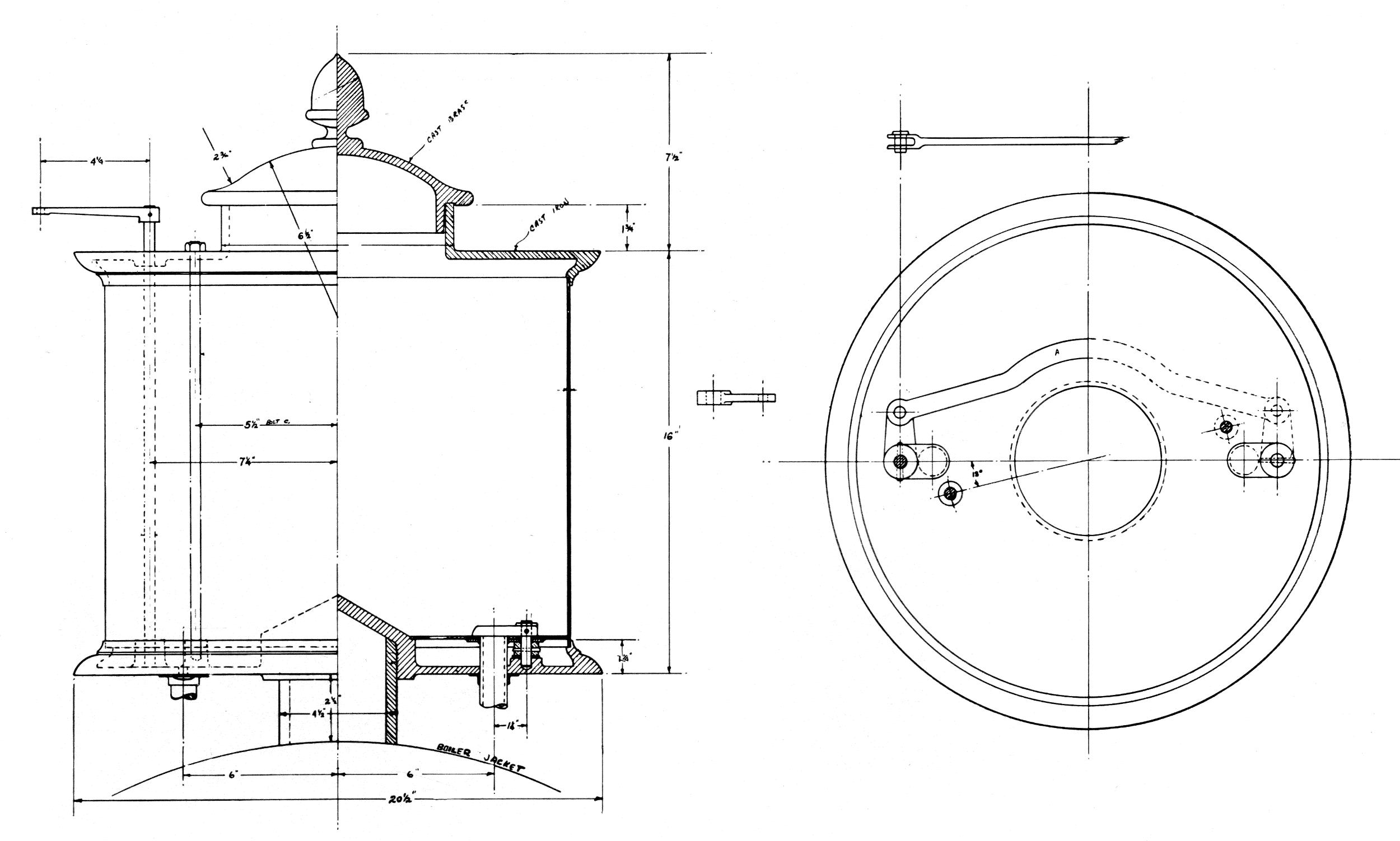
The steam dome (fig. 18) is located directly over the firebox, inside the cab. It is lagged and jacketed in an identical manner to the boiler. The shell of the dome is of 5/16-inch wrought iron, the top cap is a cast-iron plate which also serves as a manhole cover offering access to the boiler’s interior for inspection and repair.
")
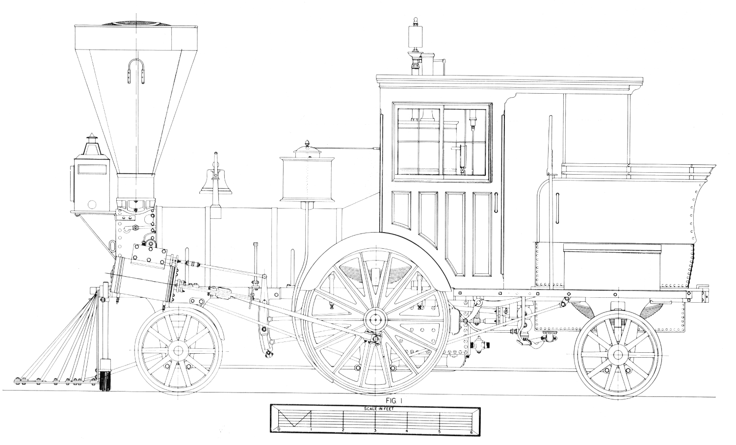
Figure 17.—“Pioneer” locomotive. (Drawing by J. H. White.)
")
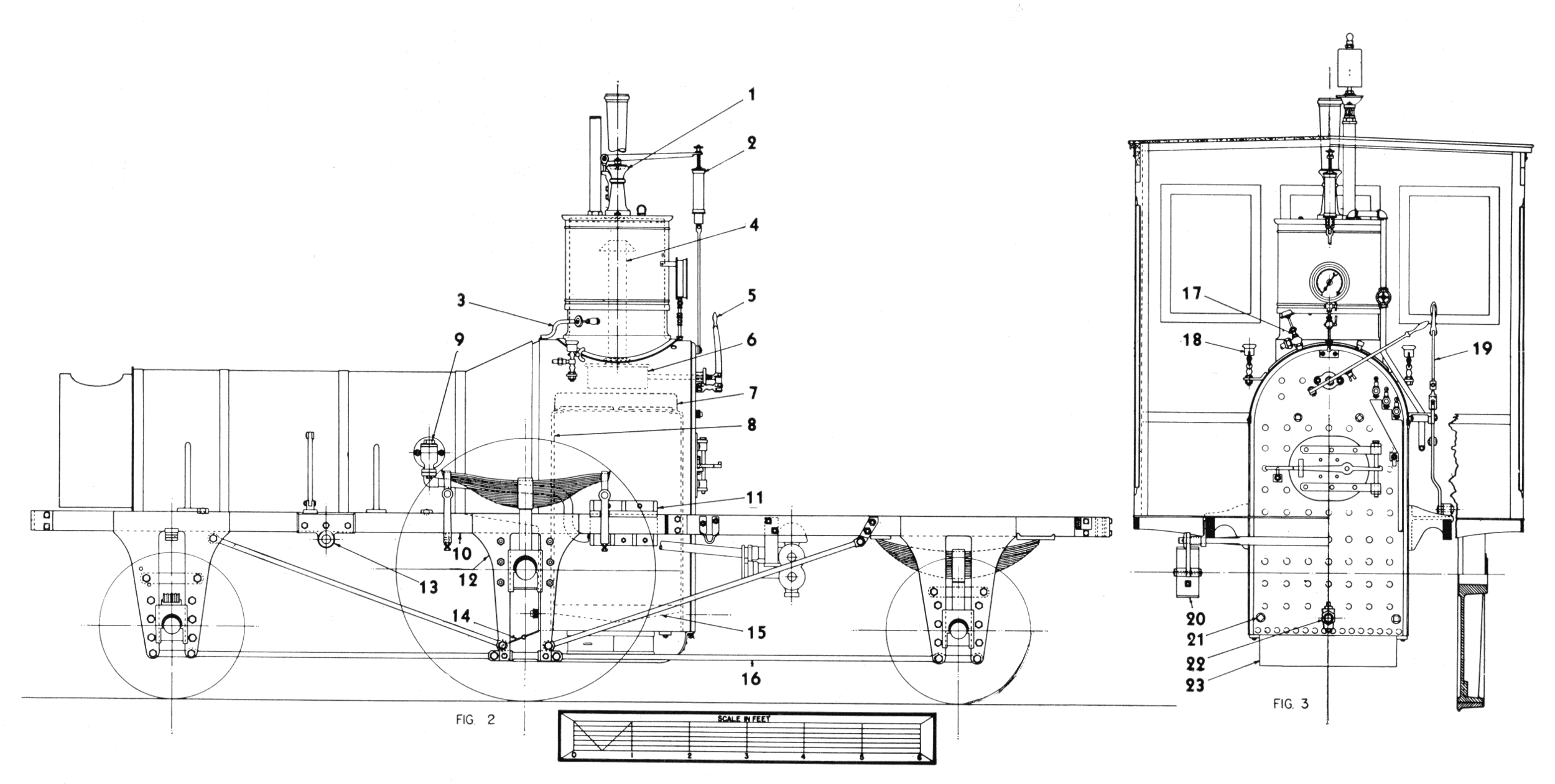
Figure 18.—“Pioneer” locomotive, (1) Safety valve, (2) spring balance, (3) steam jet, (4) dry pipe, (5) throttle lever, (6) throttle, (7) crown bar, (8) front tube sheet, (9) check valve, (10) top rail, (11) rear-boiler bracket, (12) pedestal, (13) rocker bearing, (14) damper, (15) grate, (16) bottom rail, (17) pump heater valve, (18) cylinder lubricator, (19) reversing lever, (20) brake shoe, (21) mud ring, (22) blowoff cock, (23) ashpan. (Drawing by J. H. White.)
A round plate, 20 inches in diameter, riveted on the forward end of the boiler, just behind the bell stand, was found when the old jacket was removed in May 1963. The size and shape of the hole, which the plate[Pg 258] covers, indicate that a steam dome or manhole was located at this point. It is possible that this was the original location of the steam dome since many builders in the early 1850’s preferred to mount the dome forward of the firebox. This was done in the belief that there was less danger of priming because the water was less agitated forward of the firebox.
The firebox is as narrow as the boiler shell and fits easily between the frame. It is a deep and narrow box, measuring 27 inches by 28 inches by about 40 inches deep, and is well suited to burning wood. A deep firebox was necessary because a wide, shallow box suitable for coal burning, allowed the fuel to burn so quickly it was difficult to fire the engine effectively. With the deep, narrow firebox, wood was filled up to the level of the fire door. In this way, the fire did not burn so furiously and did not keep ahead of the fireman; at the same time, since it burned so freely, a good fire was always on hand. The Pioneer burned oak and hickory.[14] For the firebox 5/16-inch thick sheet was used, for heavier sheet would have blistered and flaked off because of the intense heat of the fire and the fibrous quality of wrought-iron sheet of the period. Sheet iron was fabricated from many small strips of iron rolled together while hot. These strips were ideally welded into a homogeneous sheet, but in practice it was found the thicker the sheet the less sure the weld.
The fire grates are cast iron and set just a few inches above the bottom of the water space so that the water below the grates remains less turbulent and mud or other impurities in the water settle here. Four bronze mud plugs and a blowoff cock are fitted to the base of the firebox so that the sediment thus collected can be removed (figs. 17, 18).
The front of the boiler is attached to the frame by the smokebox, which is a cylinder, bolted on a light, cast-iron saddle (not part of the cylinder castings nor attached to them, but bolted directly to the top rail of the frame; it may be a hastily made repair put on at the shops of the C.V.R.R.). The rear of the boiler is attached to the frame by two large cast-iron brackets, one on each side of the firebox (fig. 18). These are bolted to the top rail of the frame but the holes in the brackets are undoubtedly slotted, so that they may slide since the boiler will expand about 1/4 inch when heated. In addition to the crown bars, which strengthen the crown sheet, the boiler is further strengthened by stay bolts and braces located in the wagon top over the firebox, where the boiler had been weakened by the large hole necessary for the steam dome. This boiler is a remarkably light, strong, and compact structure.
Few boiler fittings are found on the Pioneer and it appears that little was done to update the engine with more modern devices during its many years of service. With the exception of the steam gauge, it has no more boiler fitting than when it left the builder’s shop in 1851.

Figure 19.—Backhead of the Pioneer. (Smithsonian photo 48069F.)
The throttle valve is a simple slide valve and must have been primitive for the time, for the balance-poppet throttle valve was in use in this country previous to 1851. It is located directly below the steam dome even though it was common practice to place the throttle valve at the front of the boiler in the smokebox. Considering the cramped condition inside the smokebox, there would seem to be little space for the addition of the throttle valve; hence its present location. The dry pipe projects up into the steam dome to gather the hottest, driest steam for the cylinders. The inverted, funnel-like cap on the top of the dry pipe is to prevent priming, as drops of water may travel up the sides of the pipe and then to the cylinders, with the possibility of great damage. After the steam enters the throttle valve it passes through the front end of the valve, through the top of the boiler via the dry pipe (fig. 18), through the front tube sheet, and then to the cylinders via the petticoat pipes. The throttle lever is a simple arrangement readily understood from the drawings. It has no latch and the throttle lever is held in any desired setting by the wingnut and quadrant shown in figure 18. The water level in the boiler is indicated by the three brass cocks located on the backhead. No gauge glass is used; they were not employed in this country until the 1870’s, although they were commonly used in England at the time the Pioneer was built.
While two safety valves were commonly required, only one was used on the Pioneer. The safety valve is located on top of the steam dome. Pressure is exerted on the lever by a spring balance, fixed at the forward end by a knife-blade bearing. The pressure can be adjusted by the thumbscrew on the balance. The graduated scale on the balance gave a general but uncertain indication of the boiler pressure. The valve itself is a poppet held against the face of the valve seat by a second knife blade attached to the[Pg 259] lever. The ornamental column forming the stand of the safety valve is cast iron and does much to decorate the interior of the cab. The pipe carrying the escaping steam projects through the cab roof. It is made of copper with a decorative brass band. This entire mechanism was replaced by a modern safety valve for use at the Chicago Railroad Fair (1949). Fortunately, the old valve was preserved and has since been replaced on the engine.
The steam gauge is a later addition, but could have been put on as early as the 1860’s, since the most recent patent date that it bears is 1859. It is an Ashcroft gauge having a handsome 4—4—0 locomotive engraved on its silver face.
The steam jet (item 3, fig. 18) is one of the simplest yet most notable boiler fitting of the Pioneer, being nothing more than a valve tapped into the base of the steam dome with a line running under the boiler jacket to the smokestack. When the valve is opened a jet of steam goes up the stack, creating a draft useful for starting the fire or enlivening it as necessary. This device was the invention of Alba F. Smith in 1852, according to the eminent 19th-century technical writer and engineer Zerah Colburn.[15]
The two feedwater pumps (fig. 20) are located beneath the cab deck (1, fig. 17). They are cast-iron construction and are driven by an eccentric on the driving-wheel axle (fig. 27). The airchamber or dome (1, fig. 27) imparts a more steady flow of the water to the boiler by equalizing the surges of water from the reciprocating pump plunger. A steam line (3, fig. 18), which heats the pump and prevents freezing in cold weather, is regulated by a valve in the cab (figs. 18, 27). Note that the line on the right side of the cab has been disconnected and plugged.
The eccentric drive for the pumps is unusual, and the author knows of no other American locomotive so equipped. Eastwick and Harrison, it is true, favored an eccentric drive for feed pumps, but they mounted the eccentric on the crankpin of the rear driving wheel and thus produced in effect a half-stroke pump. This was not an unusual arrangement, though a small crank was usually employed in place of the eccentric. The full-stroke crosshead pump with which the Jenny Lind (fig. 22) is equipped, was of course the most common style of feed pump used in this country in the 19th century.
Of all the mechanisms on a 19th-century locomotive, the feed pump was the most troublesome. If an engineer could think of nothing else to complain about, he could usually call attention to a defective pump and not be found a liar. Because of this, injectors were adopted after their introduction in 1860. It is surprising that the Pioneer, which was in regular service as late as 1880 and has been under steam many times since for numerous exhibitions, was never fitted with one of these devices. Because its stroke is[Pg 260] short and the plunger is in less rapid motion, the present eccentric arrangement is more complex but less prone to disorder than the simpler but faster crosshead pump.

Figure 20.—Feedwater pump of the Pioneer. (Smithsonian photo 63344.)
The check valves are placed slightly below the centerline of the boiler (fig. 18). These valves are an unfinished bronze casting and appear to be of a recent pattern, probably dating from the 1901 renovation. At the time the engine was built, it was usual to house these valves in an ornamental spun-brass casing. The smokestack is of the bonnet type commonly used on wood-burning locomotives in this country between about 1845 and 1870. The exhaust steam from the cylinders is directed up the straight stack (shown in phantom in fig. 27) by the blast pipe. This creates a partial vacuum in the smokebox that draws the fire, gases, ash, and smoke through the boiler tubes from the firebox. The force of the exhausting steam blows them out the stack. At the top of the straight stack is a deflecting cone which slows the velocity of the exhaust and changes its direction causing it to go down into the funnel-shaped outer casing of the stack. Here, the heavy embers and cinders are collected and prevented from directly discharging into the countryside as dangerous firebrands. Wire netting is stretched overtop of the deflecting cone to catch the lighter, more volatile embers which may defy the action of the cone. The term “bonnet stack” results from the fact that this netting is similar in shape to a lady’s bonnet. The cinders thus accumulated in the stack’s hopper could be emptied by opening a plug at the base of the stack.
While the deflecting cone was regarded highly as a spark arrester and used practically to the exclusion of any other arrangement, it had the basic defect of keeping the smoke low and close to the train. This was a great nuisance to passengers, as the low trailing smoke blew into the cars. If the exhaust had been allowed to blast straight out the stack high into the air, most of the sparks would have burned out before touching the ground.

Figure 21.—“Pioneer” on exhibit in old Arts and Industries building of the Smithsonian Institution. In this view can be seen the bonnet screen of the stack and arrangement of the boiler-frame braces and other details not visible from the floor. (Smithsonian photo 48069A.)

Figure 22.—“Jenny Lind,” sister engine of the Pioneer, shown here as rebuilt in 1878 for use as an inspection engine. It was scrapped in March 1905. (Photo courtesy of E. P. Alexander.)

Figure 23.—Cylinder head with valve box removed.

Figure 24.—Bottom of valve box with slide valve removed.


Figures 25 and 26.—Cylinder with valve box removed, showing valve face.
The frame of the Pioneer defies an exact classification but it more closely resembles the riveted- or sandwich-type frame than any other (figs. 18, 27). While the simple bar frame enjoyed the greatest popularity in the last century, riveted frames were widely used in this country, particularly by the New England builders between about 1840 and 1860. The riveted frame was fabricated from two plates of iron, about 5/8-inch thick, cut to the shape of the top rail and the pedestal. A bar about 2 inches square was riveted between the two plates. A careful study of photographs of Hinkley and other New England-built engines of the period will reveal this style of construction. The frame of the Pioneer differs from the usual riveted frame in that the top rail is 1-3/4 inches thick by 4-1/8 inches deep and runs the length of the locomotive. The pedestals are made of two 3/8-inch plates flush-riveted to each side of the top rail. The cast-iron shoes which serve as guides for the journal boxes also act as spacers between the pedestal plates.
The bottom rail of the frame is a 1-1/8-inch diameter rod which is forged square at the pedestals and forms the pedestal cap. The frame is further stiffened by two diagonal rods running from the top of each truck-wheel pedestal to the base of the driving-wheel pedestal, forming a truss. Six rods, riveted to the boiler shell and bolted to the frame’s top rail, strengthen the frame laterally. Four of these rods can be seen easily as they run from the frame to the middle of the boiler; the other two are riveted to the underside of the boiler. The attachment of these rods to the boiler was an undesirable practice, for the boiler shell[Pg 264] was thus subjected to the additional strain of the locomotive’s vibrations as it passed over the road. In later years, as locomotives grew in size, this practice was avoided and frames were made sufficiently strong to hold the engine’s machinery in line without using the boiler shell.
The front and rear frame beams are of flat iron plate bolted to the frame. The rear beam had been pushed in during an accident, and instead of its being replaced, another plate was riveted on and bent out in the opposite direction to form a pocket for the rear coupling pin. Note that there is no drawbar and that the coupler is merely bolted to the beams. Since the engine only pulled light trains, the arrangement was sufficiently strong.
The running gear is simply sprung with individual leaf springs for each axle; it is not connected by equalizing levers. To find an American locomotive not equipped with equalizers is surprising since they were almost a necessity to produce a reasonably smooth ride on the rough tracks of American railroads. Equalizers steadied the motion of the engine by distributing the shock received by any one wheel or axle to all the other wheels and axles so connected, thus minimizing the effects of an uneven roadbed. The author believes that the Pioneer is a hard-riding engine.
The springs of the main drives are mounted in the usual fashion. The rear boiler bracket (fig. 18) is slotted so that the spring hanger may pass through for its connection with the frame. The spring of the leading wheels is set at right angles to the frame (fig. 27) and bears on a beam, fabricated of iron plate, which in turn bears on the journal boxes. The springs of the trailing wheels are set parallel with the frame and are mounted between the pedestal plates (fig. 18).
The center of the driving wheel is cast iron and has spokes of the old rib pattern, which is a T in cross section, and was used previous to the adoption of the hollow spoke wheel. In the mid-1830’s Baldwin and others used this rib-pattern style of wheel, except that the rib faced inside. The present driving-wheel centers are unquestionably original. The sister engine Jenny Lind (fig. 22) was equipped with identical driving wheels. The present tires are very thin and beyond their last turning. They are wrought iron and shrunk to fit the wheel centers. Flush rivets are used for further security. The left wheel, shown in figure 17, is cracked at the hub and is fitted with an iron ring to prevent its breaking.
The truck wheels, of the hollow spoke pattern, are cast iron with chilled treads. They were made by Asa Whitney, one of the leading car-wheel manufacturers in this country, whose extensive plant was located in Philadelphia. Made under Whitney’s patent of 1866, these wheels may well have been added to the Pioneer during the 1871 rebuilding. Railroad wheels were not cast from ordinary cast iron, which was too weak and brittle to stand the severe service for which they were intended, but from a high-quality cast iron similar to that used for cannons. Its tensile strength, which ranged from 31,000 to 36,000 psi, was remarkably high and very nearly approached that of the best wrought-iron plate.
The cylinders are cast iron with an 8-1/2-inch bore about half the size of the cylinders of a standard 8-wheel engine. The cylinders are bolted to the frame but not to the saddle, and are set at a 9° angle to clear the leading wheels and at the same time to line up with the center of the driving-wheel axle. The wood lagging is covered with a decorative brass jacket. Ornamental brass jacketing was extensively used on mid-19th-century American locomotives to cover not only the cylinders but steam and sand boxes, check valves, and valve boxes. The greater expense for brass (Russia iron or painted sheet iron were a cheaper substitute) was justified by the argument that brass lasted the life of the engine, and could be reclaimed for scrap at a price approaching the original cost; and also that when brightly polished it reflected the heat, preventing loss by radiation, and its bright surface could be seen a great distance, thus helping to prevent accidents at grade crossings. The reader should be careful not to misconstrue the above arguments simply as rationalization on the part of master mechanics more intent on highly decorative machines than on the practical considerations involved.
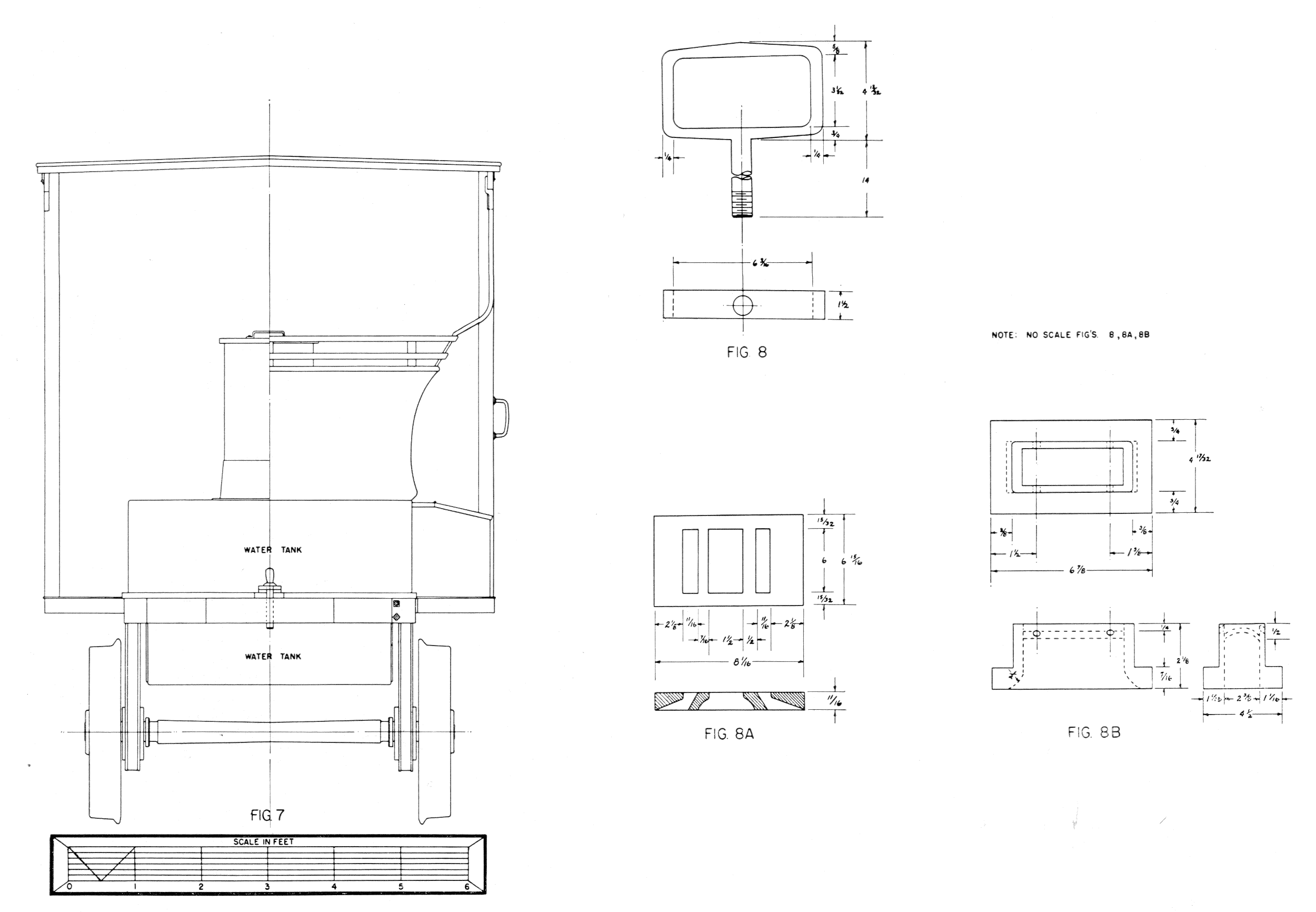
The valve box, a separate casting, is fastened to the cylinder casting by six bolts. The side cover plates when removed show only a small opening suitable for inspection and adjustment of the valve. The valve box must be removed to permit repair or removal of the valve. A better understanding of this mechanism and the layout of the parts can be gained from a study of figures 23-26, 28 (8, 8A, and 8B).

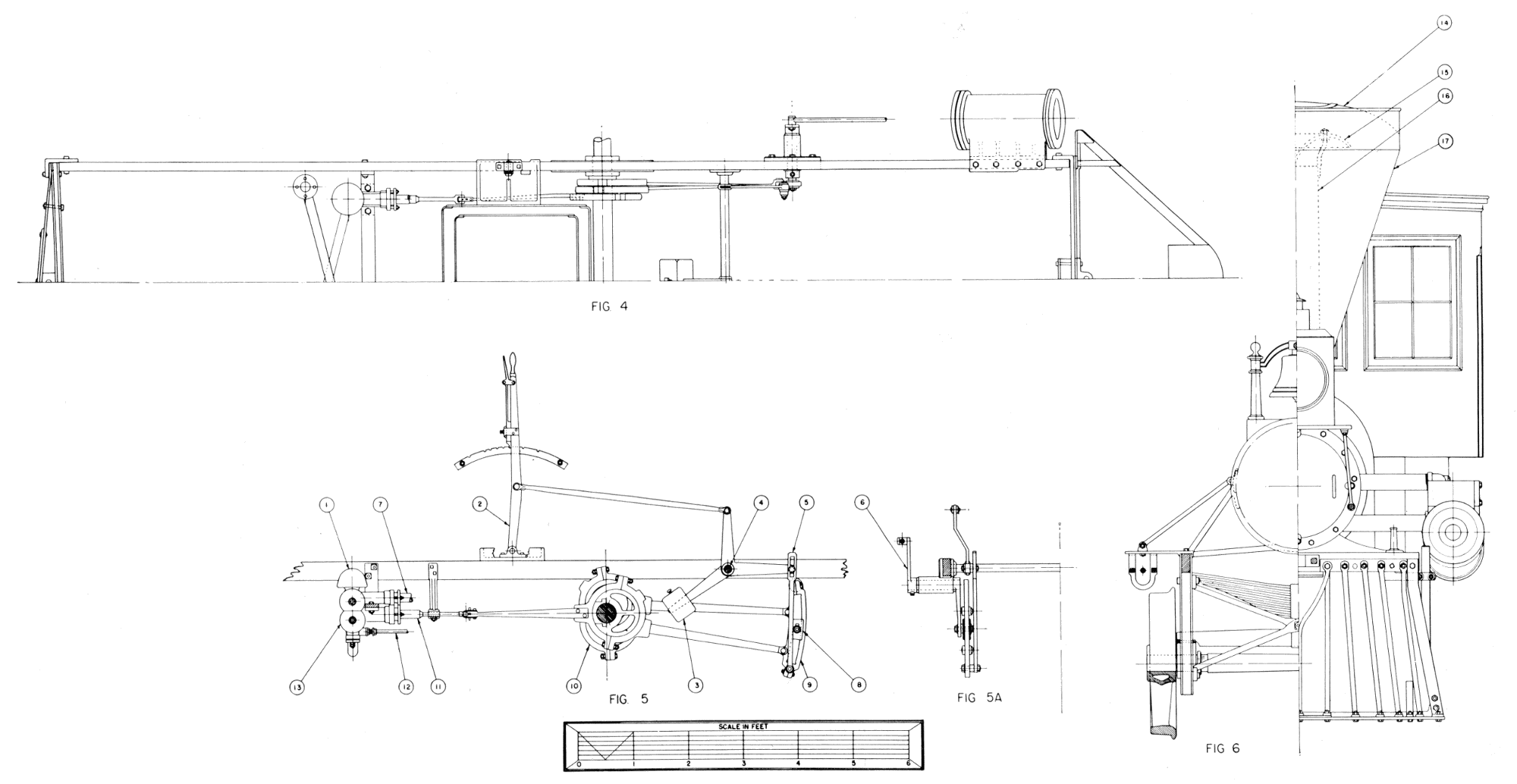
Figure 27.—“Pioneer” locomotive. (1) Air chamber, (2) reversing lever, (3) counterweight, (4) reversing shaft, (5) link hanger, (6) rocker, (7) feedwater line to boiler, (8) link block, (9) link, (10) eccentric, (11) pump plunger, (12) pump steamheater line, (13) feedwater pump, (14) wire netting [bonnet], (15) deflecting cone, (16) stack, (17) stack hopper. (Drawing by J. H. White.)

Figure 28.—Rear elevation of Pioneer and detail of valve shifter; valve face and valve. (Drawing by J. H. White.)
Both crossheads were originally of cast iron but one of these has been replaced and is of steel. They run into steel guides, bolted at the forward end to the rear cylinder head and supported in the rear by a yoke. The yoke is one of the more finished and better made pieces on the entire engine (fig. 27). The main rod is of the old pattern, round in cross section, and only 1-1/2 inches in diameter at the largest point.
The valve gear is of the Stephenson shifting-link pattern (see fig. 27), a simple and dependable motion used extensively in this country between about 1850 and 1900. The author believes that this is the original valve gear of the Pioneer, since the first mention (1854) in the Annual Report of the Cumberland Valley Railroad of the style of valve gear used by each engine, states that the Pioneer was equipped with a shifting-link motion. Assuming this to be the original valve gear of the Pioneer, it must be regarded as an early application, because the Stephenson motion was just being introduced into American locomotive practice in the early 1850’s. Four eccentrics drive the motion; two are for forward motion and two for reverse. The link is split and made of two curved pieces. The rocker is fabricated of several forged pieces keyed and bolted together. On better made engines the rocker would be a one-piece forging. The lower arm of each rocker is curiously shaped, made with a slot so that the link block may be adjusted. Generally, the only adjustment possible was effected by varying the length of the valve stem by the adjusting nuts provided. A simple weight and lever attached to the reversing shaft serve as a counterbalance for the links and thus assist the engineer in shifting the valve motion. There are eight positions on the quadrant of the reversing lever.

Figure 29.—“Pioneer” on exhibit in old Arts and Industries building, showing the tank and backhead. (Smithsonian photo 48069E.)
The cab is solid walnut with a natural finish. It is very possible that the second cab was added to the locomotive after the 1862 fire. A brass gong used by the[Pg 267] conductor to signal the engineer is fastened to the underside of the cab roof. This style of gong was in use in the 1850’s and may well be original equipment.
The water tank is in two sections, one part extending below the deck, between the frame. The tank holds 600 gallons of water. The tender holds one cord of wood.
The small pedestal-mounted sandbox was used on several Cumberland Valley engines including the Pioneer. This box was removed from the engine sometime between 1901 and 1904. It was on the engine at the time of the Carlisle sesquicentennial but disappeared by the time of the St. Louis exposition. Two small sandboxes, mounted on the driving-wheel splash guards, replaced the original box. The large headlamp (fig. 3) apparently disappeared at the same time and was replaced by a crudely made lamp formerly mounted on the cab roof as a backup light. Headlamps of commercial manufacture were carefully finished and made with parabolic reflectors, elaborate burners, and handsomely fitted cases. Such a lamp could throw a beam of light for 1000 feet. The present lamp has a flat cone-shaped piece of tin for a reflector.
The brushes attached to the pilot were used in the winter to brush snow and loose ice off the rail and thus improve traction. In good weather the brushes were set up to clear the tracks.

Figure 30.—Reconstructed sandbox replaced on the locomotive, August 1962. (Drawing by J. H. White.)
After the Pioneer had come to the National Museum, it was decided that some refinishing was required to return it as nearly as possible to the state of the original engine. Replacing the sandbox was an obvious change.[20] The brass cylinder jackets were also replaced. The cab was stripped and carefully refinished as natural wood. The old safety valve was replaced, [Pg 268]as already mentioned. Rejacketing the boiler with simulated Russia iron produced a most pleasing effect, adding not only to the authenticity of the display but making the engine appear lighter and relieving the somber blackness which was not characteristic of a locomotive of the 1850’s. Several minor replacements are yet to be done; chiefly among these are the cylinder-cock linkage and a proper headlamp.
The question arises, has the engine survived as a true and accurate representation of the original machine built in 1851? In answer, it can be said that although the Pioneer was damaged en route to the Cumberland Valley Railroad, modified on receipt, burned in 1862, and operated for altogether nearly 40 years, surprisingly few new appliances have been added, nor has the general arrangement been changed. Undoubtedly, the main reason the engine is so little changed is that its small size and odd framing did not invite any large investment for extensive alteration for other uses. But there can be no positive answer as to its present variance from the original appearance as represented in the oldest known illustration of it—the Hull drawing of 1871 (fig. 8). There are few, if any, surviving 19th-century locomotives that have not suffered numerous rebuildings and are not greatly altered from the original. The John Bull, also in the U.S. National Museum collection, is a good example of a machine many times rebuilt in its 30 years of service.[21] Unless other information is uncovered to the contrary, it can be stated that the Pioneer is a true representation of a light passenger locomotive of 1851.
[1] Minutes of the Board of Managers of the Cumberland Valley Railroad. This book may be found in the office of the Secretary, Pennsylvania Railroad, Philadelphia, Pa., June 25, 1851. Hereafter cited as “Minutes C.V.R.R.”
[2] Ibid.
[3] Minutes C.V.R.R.
[4] Franklin Repository (Chambersburg, Pa.), August 26, 1909.
[5] Railroad Advocate (December 29, 1855), vol. 2, p. 3.
[6] C. E. Fisher, “Locomotives of the New Haven Railroad, ” Railway and Locomotive Historical Society Bulletin (April 1938), no. 46, p. 48.
[7] Minutes C.V.R.R.
[8] Evening Sentinel (Carlisle, Pa.), October 23, 1901.
[9] Norwich Bulletin (Norwich, Conn.), July 24, 1879. All data regarding A. F. Smith is from this source unless otherwise noted.
[10] Railway Age (September 13, 1889), vol. 14, no. 37. Page 600 notes that Tyler worked on C.V.R.R. 1851-1852; Smith’s obituary (footnote 9) mentions 1849 as the year; and minutes of C.V.R.R. mention Tyler as early as 1850.
[11] Minutes C.V.R.R.
[12] A. F. Holley, American and European Railway Practice (New York: 1861). An illustration of Smith’s superheater is shown on plate 58, figure 13.
[13] John H. White, “Introduction of the Locomotive Safety Truck,” (Paper 24, 1961, in Contributions from the Museum of History and Technology: Papers 19-30, U.S. National Museum Bulletin 228; Washington: Smithsonian Institution, 1963), p. 117.
[14] Annual Report, C.V.R.R., 1853.
[15] Zerah Colburn, Recent Practice in Locomotive Engines (1860), p. 71.
[16] Railroad Gazette (September 27, 1907), vol. 43, no. 13, pp. 357-360. These notes on Wilmarth locomotives by C. H. Caruthers were printed with several errors concerning the locomotives of the Cumberland Valley Railroad and prompted the preparation of these present remarks on the history of Wilmarth’s activities. Note that on page 359 it is reported that only one compensating-lever engine was built for the C.V.R.R. in 1854, and not two such engines in 1852. The Pioneer is incorrectly identified as a “Shanghai,” and as being one of three such engines built in 1871 by Wilmarth.
[17] The author is indebted to Thomas Norrell for these and many of the other facts relating to Wilmarth’s Union Works.
[18] Railroad Gazette (October 1907), vol. 43, p. 382.
[19] Boston Daily Evening Telegraph (Boston, Mass.), August 11, 1854. The article stated that one engine a week was built and that 10 engines were already completed for the Erie. Construction had started on 30 others.
[20] The restoration work has been ably handled by John Stine of the Museum staff. Restoration started in October 1961.
[21] S. H. Oliver, The First Quarter Century of the Steam Locomotive in America (U.S. National Museum Bulletin 210; Washington: Smithsonian Institution, 1956), pp. 38-46.
U.S. GOVERNMENT PRINTING OFFICE: 1964
For sale by the Superintendent of Documents, U.S. Government Printing
Office
Washington, D.C., 20402—Price 30 cents.
Adams, W. B., 252
Baldwin, Matthias William, 264
Boston Locomotive Works, 260
Colburn, Zerah, 259
Danforth Cooke & Co., 252
Drury, Gardner P., 260
Eastwick, Andrew M., 259
Harrison, Joseph, Jr., 259
Hinkley, Holmes, 252, 260, 263
Smith, Alba F., 244, 246, 247, 259
Stephenson, Robert, & Hawthorns, Ltd., 253
Stuart, J. E. B., 249
Taunton Locomotive Works, 247
Union Works, 260
Vulcan Foundry, 252
Watts, Frederick, 249
Westhaeffer, Paul, 251
Wilmarth, Seth, 244, 246, 247, 249, 260
Winters, Joseph, 244
Transcriber's corrections:
P. 259: ‘1880 and has been under steam’—was ‘1880 and has been under stream.’
P. 267: ‘made with parabolic reflectors’—was ‘made with parobolic reflectors.’
End of the Project Gutenberg EBook of The 'Pioneer': Light Passenger
Locomotive of 1851, by John H. White

*** END OF THIS PROJECT GUTENBERG EBOOK LIGHT PASSENGER LOCOMOTIVE ***

***** This file should be named 28160-h.htm or 28160-h.zip *****
This and all associated files of various formats will be found in:
        http://www.gutenberg.org/2/8/1/6/28160/

Produced by Chris Curnow, Louise Pattison, Joseph Cooper
and the Online Distributed Proofreading Team at
http://www.pgdp.net


Updated editions will replace the previous one--the old editions
will be renamed.

Creating the works from public domain print editions means that no
one owns a United States copyright in these works, so the Foundation
(and you!) can copy and distribute it in the United States without
permission and without paying copyright royalties.  Special rules,
set forth in the General Terms of Use part of this license, apply to
copying and distributing Project Gutenberg-tm electronic works to
protect the PROJECT GUTENBERG-tm concept and trademark.  Project
Gutenberg is a registered trademark, and may not be used if you
charge for the eBooks, unless you receive specific permission.  If you
do not charge anything for copies of this eBook, complying with the
rules is very easy.  You may use this eBook for nearly any purpose
such as creation of derivative works, reports, performances and
research.  They may be modified and printed and given away--you may do
practically ANYTHING with public domain eBooks.  Redistribution is
subject to the trademark license, especially commercial
redistribution.


*** START: FULL LICENSE ***

THE FULL PROJECT GUTENBERG LICENSE
PLEASE READ THIS BEFORE YOU DISTRIBUTE OR USE THIS WORK

To protect the Project Gutenberg-tm mission of promoting the free
distribution of electronic works, by using or distributing this work
(or any other work associated in any way with the phrase "Project
Gutenberg"), you agree to comply with all the terms of the Full Project
Gutenberg-tm License (available with this file or online at
http://gutenberg.org/license).


Section 1.  General Terms of Use and Redistributing Project Gutenberg-tm
electronic works

1.A.  By reading or using any part of this Project Gutenberg-tm
electronic work, you indicate that you have read, understand, agree to
and accept all the terms of this license and intellectual property
(trademark/copyright) agreement.  If you do not agree to abide by all
the terms of this agreement, you must cease using and return or destroy
all copies of Project Gutenberg-tm electronic works in your possession.
If you paid a fee for obtaining a copy of or access to a Project
Gutenberg-tm electronic work and you do not agree to be bound by the
terms of this agreement, you may obtain a refund from the person or
entity to whom you paid the fee as set forth in paragraph 1.E.8.

1.B.  "Project Gutenberg" is a registered trademark.  It may only be
used on or associated in any way with an electronic work by people who
agree to be bound by the terms of this agreement.  There are a few
things that you can do with most Project Gutenberg-tm electronic works
even without complying with the full terms of this agreement.  See
paragraph 1.C below.  There are a lot of things you can do with Project
Gutenberg-tm electronic works if you follow the terms of this agreement
and help preserve free future access to Project Gutenberg-tm electronic
works.  See paragraph 1.E below.

1.C.  The Project Gutenberg Literary Archive Foundation ("the Foundation"
or PGLAF), owns a compilation copyright in the collection of Project
Gutenberg-tm electronic works.  Nearly all the individual works in the
collection are in the public domain in the United States.  If an
individual work is in the public domain in the United States and you are
located in the United States, we do not claim a right to prevent you from
copying, distributing, performing, displaying or creating derivative
works based on the work as long as all references to Project Gutenberg
are removed.  Of course, we hope that you will support the Project
Gutenberg-tm mission of promoting free access to electronic works by
freely sharing Project Gutenberg-tm works in compliance with the terms of
this agreement for keeping the Project Gutenberg-tm name associated with
the work.  You can easily comply with the terms of this agreement by
keeping this work in the same format with its attached full Project
Gutenberg-tm License when you share it without charge with others.

1.D.  The copyright laws of the place where you are located also govern
what you can do with this work.  Copyright laws in most countries are in
a constant state of change.  If you are outside the United States, check
the laws of your country in addition to the terms of this agreement
before downloading, copying, displaying, performing, distributing or
creating derivative works based on this work or any other Project
Gutenberg-tm work.  The Foundation makes no representations concerning
the copyright status of any work in any country outside the United
States.

1.E.  Unless you have removed all references to Project Gutenberg:

1.E.1.  The following sentence, with active links to, or other immediate
access to, the full Project Gutenberg-tm License must appear prominently
whenever any copy of a Project Gutenberg-tm work (any work on which the
phrase "Project Gutenberg" appears, or with which the phrase "Project
Gutenberg" is associated) is accessed, displayed, performed, viewed,
copied or distributed:

This eBook is for the use of anyone anywhere at no cost and with
almost no restrictions whatsoever.  You may copy it, give it away or
re-use it under the terms of the Project Gutenberg License included
with this eBook or online at www.gutenberg.org

1.E.2.  If an individual Project Gutenberg-tm electronic work is derived
from the public domain (does not contain a notice indicating that it is
posted with permission of the copyright holder), the work can be copied
and distributed to anyone in the United States without paying any fees
or charges.  If you are redistributing or providing access to a work
with the phrase "Project Gutenberg" associated with or appearing on the
work, you must comply either with the requirements of paragraphs 1.E.1
through 1.E.7 or obtain permission for the use of the work and the
Project Gutenberg-tm trademark as set forth in paragraphs 1.E.8 or
1.E.9.

1.E.3.  If an individual Project Gutenberg-tm electronic work is posted
with the permission of the copyright holder, your use and distribution
must comply with both paragraphs 1.E.1 through 1.E.7 and any additional
terms imposed by the copyright holder.  Additional terms will be linked
to the Project Gutenberg-tm License for all works posted with the
permission of the copyright holder found at the beginning of this work.

1.E.4.  Do not unlink or detach or remove the full Project Gutenberg-tm
License terms from this work, or any files containing a part of this
work or any other work associated with Project Gutenberg-tm.

1.E.5.  Do not copy, display, perform, distribute or redistribute this
electronic work, or any part of this electronic work, without
prominently displaying the sentence set forth in paragraph 1.E.1 with
active links or immediate access to the full terms of the Project
Gutenberg-tm License.

1.E.6.  You may convert to and distribute this work in any binary,
compressed, marked up, nonproprietary or proprietary form, including any
word processing or hypertext form.  However, if you provide access to or
distribute copies of a Project Gutenberg-tm work in a format other than
"Plain Vanilla ASCII" or other format used in the official version
posted on the official Project Gutenberg-tm web site (www.gutenberg.org),
you must, at no additional cost, fee or expense to the user, provide a
copy, a means of exporting a copy, or a means of obtaining a copy upon
request, of the work in its original "Plain Vanilla ASCII" or other
form.  Any alternate format must include the full Project Gutenberg-tm
License as specified in paragraph 1.E.1.

1.E.7.  Do not charge a fee for access to, viewing, displaying,
performing, copying or distributing any Project Gutenberg-tm works
unless you comply with paragraph 1.E.8 or 1.E.9.

1.E.8.  You may charge a reasonable fee for copies of or providing
access to or distributing Project Gutenberg-tm electronic works provided
that

- You pay a royalty fee of 20% of the gross profits you derive from
     the use of Project Gutenberg-tm works calculated using the method
     you already use to calculate your applicable taxes.  The fee is
     owed to the owner of the Project Gutenberg-tm trademark, but he
     has agreed to donate royalties under this paragraph to the
     Project Gutenberg Literary Archive Foundation.  Royalty payments
     must be paid within 60 days following each date on which you
     prepare (or are legally required to prepare) your periodic tax
     returns.  Royalty payments should be clearly marked as such and
     sent to the Project Gutenberg Literary Archive Foundation at the
     address specified in Section 4, "Information about donations to
     the Project Gutenberg Literary Archive Foundation."

- You provide a full refund of any money paid by a user who notifies
     you in writing (or by e-mail) within 30 days of receipt that s/he
     does not agree to the terms of the full Project Gutenberg-tm
     License.  You must require such a user to return or
     destroy all copies of the works possessed in a physical medium
     and discontinue all use of and all access to other copies of
     Project Gutenberg-tm works.

- You provide, in accordance with paragraph 1.F.3, a full refund of any
     money paid for a work or a replacement copy, if a defect in the
     electronic work is discovered and reported to you within 90 days
     of receipt of the work.

- You comply with all other terms of this agreement for free
     distribution of Project Gutenberg-tm works.

1.E.9.  If you wish to charge a fee or distribute a Project Gutenberg-tm
electronic work or group of works on different terms than are set
forth in this agreement, you must obtain permission in writing from
both the Project Gutenberg Literary Archive Foundation and Michael
Hart, the owner of the Project Gutenberg-tm trademark.  Contact the
Foundation as set forth in Section 3 below.

1.F.

1.F.1.  Project Gutenberg volunteers and employees expend considerable
effort to identify, do copyright research on, transcribe and proofread
public domain works in creating the Project Gutenberg-tm
collection.  Despite these efforts, Project Gutenberg-tm electronic
works, and the medium on which they may be stored, may contain
"Defects," such as, but not limited to, incomplete, inaccurate or
corrupt data, transcription errors, a copyright or other intellectual
property infringement, a defective or damaged disk or other medium, a
computer virus, or computer codes that damage or cannot be read by
your equipment.

1.F.2.  LIMITED WARRANTY, DISCLAIMER OF DAMAGES - Except for the "Right
of Replacement or Refund" described in paragraph 1.F.3, the Project
Gutenberg Literary Archive Foundation, the owner of the Project
Gutenberg-tm trademark, and any other party distributing a Project
Gutenberg-tm electronic work under this agreement, disclaim all
liability to you for damages, costs and expenses, including legal
fees.  YOU AGREE THAT YOU HAVE NO REMEDIES FOR NEGLIGENCE, STRICT
LIABILITY, BREACH OF WARRANTY OR BREACH OF CONTRACT EXCEPT THOSE
PROVIDED IN PARAGRAPH F3.  YOU AGREE THAT THE FOUNDATION, THE
TRADEMARK OWNER, AND ANY DISTRIBUTOR UNDER THIS AGREEMENT WILL NOT BE
LIABLE TO YOU FOR ACTUAL, DIRECT, INDIRECT, CONSEQUENTIAL, PUNITIVE OR
INCIDENTAL DAMAGES EVEN IF YOU GIVE NOTICE OF THE POSSIBILITY OF SUCH
DAMAGE.

1.F.3.  LIMITED RIGHT OF REPLACEMENT OR REFUND - If you discover a
defect in this electronic work within 90 days of receiving it, you can
receive a refund of the money (if any) you paid for it by sending a
written explanation to the person you received the work from.  If you
received the work on a physical medium, you must return the medium with
your written explanation.  The person or entity that provided you with
the defective work may elect to provide a replacement copy in lieu of a
refund.  If you received the work electronically, the person or entity
providing it to you may choose to give you a second opportunity to
receive the work electronically in lieu of a refund.  If the second copy
is also defective, you may demand a refund in writing without further
opportunities to fix the problem.

1.F.4.  Except for the limited right of replacement or refund set forth
in paragraph 1.F.3, this work is provided to you 'AS-IS' WITH NO OTHER
WARRANTIES OF ANY KIND, EXPRESS OR IMPLIED, INCLUDING BUT NOT LIMITED TO
WARRANTIES OF MERCHANTIBILITY OR FITNESS FOR ANY PURPOSE.

1.F.5.  Some states do not allow disclaimers of certain implied
warranties or the exclusion or limitation of certain types of damages.
If any disclaimer or limitation set forth in this agreement violates the
law of the state applicable to this agreement, the agreement shall be
interpreted to make the maximum disclaimer or limitation permitted by
the applicable state law.  The invalidity or unenforceability of any
provision of this agreement shall not void the remaining provisions.

1.F.6.  INDEMNITY - You agree to indemnify and hold the Foundation, the
trademark owner, any agent or employee of the Foundation, anyone
providing copies of Project Gutenberg-tm electronic works in accordance
with this agreement, and any volunteers associated with the production,
promotion and distribution of Project Gutenberg-tm electronic works,
harmless from all liability, costs and expenses, including legal fees,
that arise directly or indirectly from any of the following which you do
or cause to occur: (a) distribution of this or any Project Gutenberg-tm
work, (b) alteration, modification, or additions or deletions to any
Project Gutenberg-tm work, and (c) any Defect you cause.


Section  2.  Information about the Mission of Project Gutenberg-tm

Project Gutenberg-tm is synonymous with the free distribution of
electronic works in formats readable by the widest variety of computers
including obsolete, old, middle-aged and new computers.  It exists
because of the efforts of hundreds of volunteers and donations from
people in all walks of life.

Volunteers and financial support to provide volunteers with the
assistance they need, are critical to reaching Project Gutenberg-tm's
goals and ensuring that the Project Gutenberg-tm collection will
remain freely available for generations to come.  In 2001, the Project
Gutenberg Literary Archive Foundation was created to provide a secure
and permanent future for Project Gutenberg-tm and future generations.
To learn more about the Project Gutenberg Literary Archive Foundation
and how your efforts and donations can help, see Sections 3 and 4
and the Foundation web page at http://www.pglaf.org.


Section 3.  Information about the Project Gutenberg Literary Archive
Foundation

The Project Gutenberg Literary Archive Foundation is a non profit
501(c)(3) educational corporation organized under the laws of the
state of Mississippi and granted tax exempt status by the Internal
Revenue Service.  The Foundation's EIN or federal tax identification
number is 64-6221541.  Its 501(c)(3) letter is posted at
http://pglaf.org/fundraising.  Contributions to the Project Gutenberg
Literary Archive Foundation are tax deductible to the full extent
permitted by U.S. federal laws and your state's laws.

The Foundation's principal office is located at 4557 Melan Dr. S.
Fairbanks, AK, 99712., but its volunteers and employees are scattered
throughout numerous locations.  Its business office is located at
809 North 1500 West, Salt Lake City, UT 84116, (801) 596-1887, email
business@pglaf.org.  Email contact links and up to date contact
information can be found at the Foundation's web site and official
page at http://pglaf.org

For additional contact information:
     Dr. Gregory B. Newby
     Chief Executive and Director
     gbnewby@pglaf.org


Section 4.  Information about Donations to the Project Gutenberg
Literary Archive Foundation

Project Gutenberg-tm depends upon and cannot survive without wide
spread public support and donations to carry out its mission of
increasing the number of public domain and licensed works that can be
freely distributed in machine readable form accessible by the widest
array of equipment including outdated equipment.  Many small donations
($1 to $5,000) are particularly important to maintaining tax exempt
status with the IRS.

The Foundation is committed to complying with the laws regulating
charities and charitable donations in all 50 states of the United
States.  Compliance requirements are not uniform and it takes a
considerable effort, much paperwork and many fees to meet and keep up
with these requirements.  We do not solicit donations in locations
where we have not received written confirmation of compliance.  To
SEND DONATIONS or determine the status of compliance for any
particular state visit http://pglaf.org

While we cannot and do not solicit contributions from states where we
have not met the solicitation requirements, we know of no prohibition
against accepting unsolicited donations from donors in such states who
approach us with offers to donate.

International donations are gratefully accepted, but we cannot make
any statements concerning tax treatment of donations received from
outside the United States.  U.S. laws alone swamp our small staff.

Please check the Project Gutenberg Web pages for current donation
methods and addresses.  Donations are accepted in a number of other
ways including checks, online payments and credit card donations.
To donate, please visit: http://pglaf.org/donate


Section 5.  General Information About Project Gutenberg-tm electronic
works.

Professor Michael S. Hart is the originator of the Project Gutenberg-tm
concept of a library of electronic works that could be freely shared
with anyone.  For thirty years, he produced and distributed Project
Gutenberg-tm eBooks with only a loose network of volunteer support.


Project Gutenberg-tm eBooks are often created from several printed
editions, all of which are confirmed as Public Domain in the U.S.
unless a copyright notice is included.  Thus, we do not necessarily
keep eBooks in compliance with any particular paper edition.


Most people start at our Web site which has the main PG search facility:

     http://www.gutenberg.org

This Web site includes information about Project Gutenberg-tm,
including how to make donations to the Project Gutenberg Literary
Archive Foundation, how to help produce our new eBooks, and how to
subscribe to our email newsletter to hear about new eBooks.