The SCIENTIFIC
AMERICAN BOY
OR
The Camp at Willow Clump Island
By
A. RUSSELL BOND

NEW YORK
MUNN & CO., Publishers
1906
COPYRIGHT, 1905, BY
MUNN & CO., NEW YORK
PRESS OF
THE KALKHOFF COMPANY
NEW YORK
PREFACE
All boys are nature lovers. Nothing appeals to them more than a summer vacation in the woods where they can escape from the restraints of civilization and live a life of freedom. Now, it may appear to be a bit of presumption to attempt to advise the boy camper how to spend his time. Surely the novelty of outdoor life, the fascinating charm of his surroundings, will provide him plenty of entertainment.
But, after all, a camp generally affords but two major amusements, hunting and fishing. These have been fully covered by a vast number of books. However, there is another side of camp life, particularly in a boys’ camp, which has been very little dealt with, namely, the exercise of one’s ingenuity in creating out of the limited resources at hand such devices and articles as will add to one’s personal comfort and welfare. It is, therefore, the aim of this book to 1 suggest certain diversions of this character for the boy camper which, aside from affording him plenty of physical exercise, will also develop his mental faculties, and above all stimulate that natural genius which is characteristic of every typical American boy. To this end the story contains descriptions of a large collection of articles which can be made by any boy of average intelligence, not only in the camp but at home as well.
The use of a narrative to connect the various incidents marks a departure in this class of book, and it is believed that the matter will thus be made more realistic and interesting. In all cases full directions are given for making the various articles. While it is not presumed that the directions will be slavishly followed, for this would defeat the general aim of the work, yet all the principal dimensions are given so that they can be used, if desired.
I beg to acknowledge the courtesy of Mr. Daniel C. Beard and Mr. Henry D. Cochrane in supplying a number of photographs. The directions for making the lee boards (page 119) were obtained from data 2 furnished by the latter. Many of the details recorded in the chapter on Tramping Outfits are to be accredited to Mr. Edward Thorpe. In the preparation of this book I have received valuable assistance from my colleague, Mr. A. A. Hopkins.
A. RUSSELL BOND.
New York, October, 1905.
CONTENTS
| CHAPTER I. | |
| PAGE | |
| “Bill” | 17 |
The Old Trunk. Christmas Vacation. “Bill’s” Skate Sail. Willow Clump Island. Organizing the Society. | |
| CHAPTER II. | |
| Skate Sails | 26 |
The Double Swedish Sail. The Single Swedish Sail. The Lanteen Sail. The Danish Sail. Bat’s Wings. | |
| CHAPTER III. | |
| Snow Shoes, Skis and Swamp Shoes | 35 |
Chair Seat Snow Shoe. Barrel Stave Snow Shoe. Barrel Hoop Snow Shoe. The Sioux Snow Shoe. The Iroquois Snow Shoe. The Ainu Snow Shoe. The Norwegian Ski. The Swamp Shoe or Swiss Snow Shoe. | |
| CHAPTER IV. | |
| Tent Making | 44 |
Farewell Meeting. Word from Uncle Ed. The Canvas Tent. Adjustable Ridge Pole. Tie Blocks. The Annex. | |
| CHAPTER V. | |
| Preparing for the Expedition | 53 |
Tent Fly. Provisions and Supplies. Umbrella Rib Crossbow. Megaphone. The Scow. | |
| CHAPTER VI. | |
| Off to the Island | 63 |
A Unique Alarm Clock. The Trip to the Island. Preliminary Exploration. A Rustic Table. The Small Filter. The Barrel Filter. The Klepalo. | |
| CHAPTER VII. | |
| Surveying | 73 |
The Surveying Instrument. Spirit Levels. The Tripod. Surveyor’s Chain. Surveyor’s Rod. A Simple Method of Surveying. Mapping the Island. | |
| CHAPTER VIII. | |
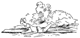
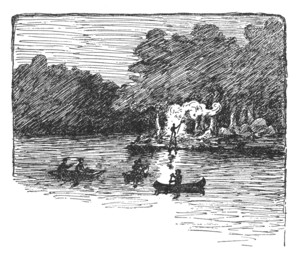
| Swimming | 84 |
Swimming on a Plank. Shooting the Rapids. Restoring the Drowned. How to Work over a Patient Alone. | |
| CHAPTER IX. | |
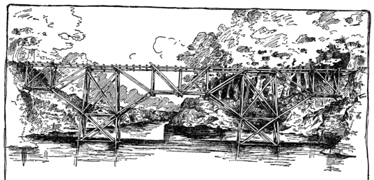
| Bridge Building | 95 |
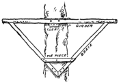
The Spar Bridge. The Rope Railway. The Suspension Bridge. The Pontoon Bridge. The King Rod Truss. Stiffening the Bridge. The King Post Bridge. | |
| CHAPTER X. | |
| Canvas Canoes | 109 |
Uncle Ed’s Departure. A Visit from Mr. Schreiner. The Sailing Canoe. Stretching on the Canvas. The Rudder. The Deep Keel. Canoe Sails. Lee Boards. Indian Paddling Canoe. | |
| CHAPTER XI. | |
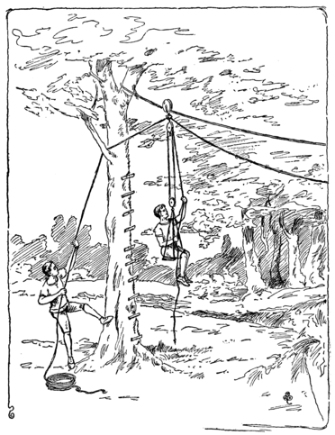
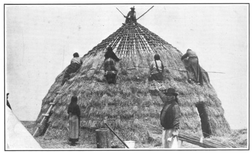
| House Building | 124 |
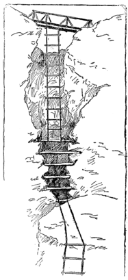
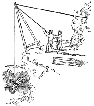
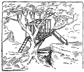
The Grass Hut. The Goblins’ Dancing Platform. Dutchy Takes a Dare. A Path Up the Fissure. Rope Ladders. The Derrick. The Tree House. Sliding Doors. | |
| CHAPTER XII. | |
| Trouble with the Tramps | 138 |
The Scow is Stolen. A Council of War. Vengeance. A Double Surprise. Tramp-proof Boat Mooring. | |
| CHAPTER XIII. | |
| Wigwagging and Heliographing | 144 |
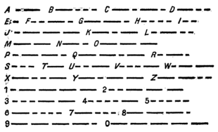
Wigwag Signals. The Wigwag Alphabet. Abbreviations. Wigwagging at Night. The Heliograph. The Single Mirror Instrument. The Sight Rod. The Screen. Focusing the Instrument. Heliograph Signaling. The International Telegraph Code. The Double Mirror Instrument. | |
| CHAPTER XIV. | |
| Ice Boats, Sledges and Toboggans | 158 |
Breaking Camp. The Ice Boat. The Sledge. The Toboggan. The Rennwolf. Ice Creepers. | |
| CHAPTER XV. | |
| The Subterranean Club | 171 |
A Cave-in. Excavating for the Cave. Covering the Cave. The Big Bug Club. Midnight Banquets. The Club Pin. The Combination Lock. | |
| CHAPTER XVI. | |
| Scooters | 183 |
A Sail in the Scow. Our Craft Strikes the Ice. The Scooter Scow. A Sprit Sail. Scooter Sailing. A Meeting of the Society. An Interview with Mr. Van Syckel. The Scooter Canoe. | |
| CHAPTER XVII. | |
| An Arctic Expedition | 193 |
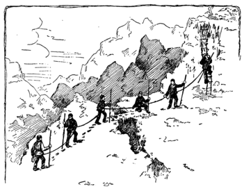
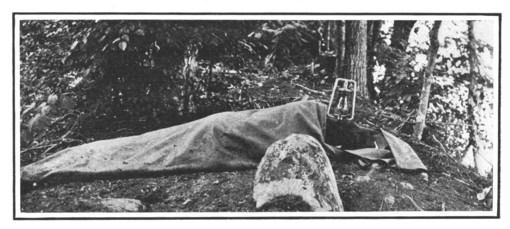
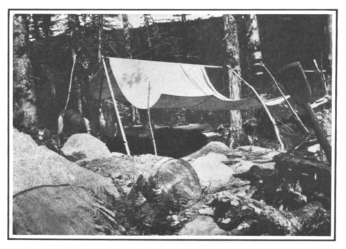
Willow Clump Island in Winter. Kindling a Camp Fire. The Outdoor Fireplace. A Stone-paved Fireplace. A Cold Night in the Hut. Mountain Climbing. A Poor Shelter. A Costly Camp Fire. A Friend in Time of Trouble. | |
| CHAPTER XVIII. | |
| Tramping Outfits | 203 |
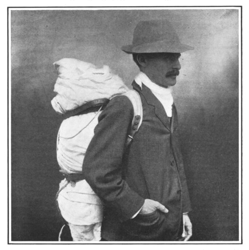
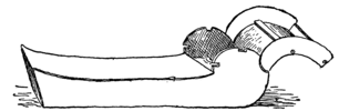
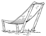
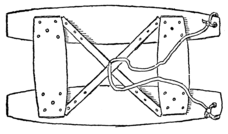
Sleeping Bags. Bill’s “Mummy Case.” The “A” Tent. A Camp Chair. A Camp Bed. The Camp Bed in a Shower. A Nightmare. Pack Harness. Riveting. | |
| CHAPTER XIX. | |
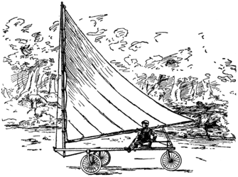
| The Land Yacht | 215 |
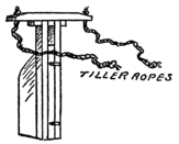
The Frame of the Yacht. A Simple Turnbuckle. Stepping the Mast. Mounting the Frame on Bicycle Wheels. The Tiller. A “Leg-of-Mutton” Sail. A Sail Through the Country. | |
| CHAPTER XX. | |
| Easter Vacation | 224 |
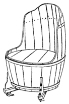
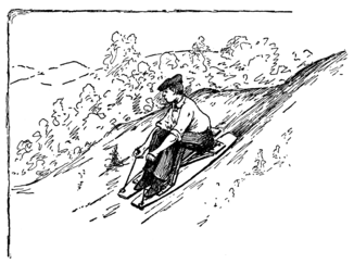
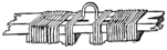
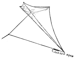
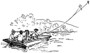
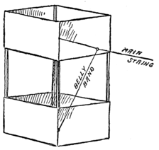
Bill’s Cave. The Barrel Stave Hammock. The Barrel Armchair. The Summer Toboggan. Tailless Kites. A Five-foot Malay Kite. An Eight-foot Malay Kite. The Elastic Belly Band. Putting the Kites to Work. The Diamond Box Kite. | |
| CHAPTER XXI. | |
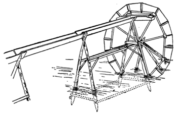
| The Water Wheel | 240 |
The Water Wheel. Surveying for the Water Wheel. Towers for the Water Wheel. The Wheel. The Buckets. The Paddles. The Receiving Trough. Setting Up the Towers. Mounting the Water Wheel. Cooling the Filter Barrel. The Canvas Bucket. Mr. Halliday’s Water Wheel. | |
| CHAPTER XXII. | |
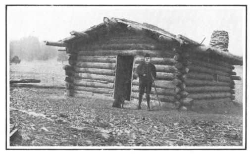
| The Log Cabin | 254 |
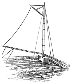
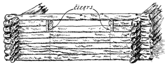
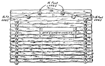
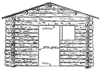
Foundation of Log Cabin. A Logging Expedition. The Log Raft. The Sail-Rigged Raft. Building the Log Cabin. The Roof of the Log Cabin. Door and Window Frames. The Fireplace. The Proper Way to Build a Stone Wall. The Floor of the Cabin. The Door Hinges and Latch. The Window Sash. Bunks. Stopping up the Chinks. | |
| CHAPTER XXIII. | |
| The Windmill | 273 |
Digging the Well. The Windmill Tower. The Crank Shaft. The Wind Wheel. A Simple Brake. The Pump. Pump Valves. Action of the Pump. | |
| CHAPTER XXIV. | |
| The Gravity Railroad | 283 |
The Car. The Flanged Wheels. Car Axles. Mounting the Wheels. The Railway Track. The Carpenter’s Miter Box. Laying the Track. The First Railway Accident. Testing the Track. | |
| CHAPTER XXV. | |
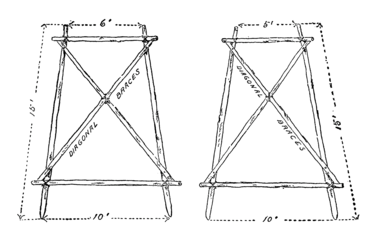
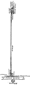
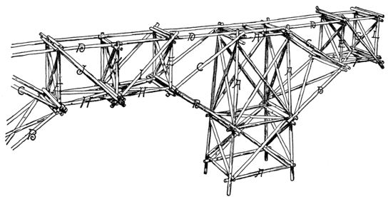
| The Cantilever Bridge | 292 |
Frames for the Cantilever Bridge. Erecting the Towers. Setting up the Frames. Binding and Anchoring the Structure. The Center Panels of the Bridge. A Serious Interruption. Dispossessed. Farewell to Willow Clump Island. Reddy’s Cantilever Bridge. | |
“Bill,” he was it, the Scientific American Boy, I mean. Of course, we were all American boys and pretty scientific chaps too, if I do say it myself, but Bill, well he was the whole show. What he didn’t know wasn’t worth knowing, so we all thought, and even to this day I sometimes wonder how he managed to contrive and execute so many remarkable plans. At the same time he was not a conceited sort of a chap and didn’t seem to realize that he was head and shoulders above the rest of us in ingenuity. But, of course, we didn’t all have an uncle like Bill did. Bill’s Uncle Ed was one of those rare men who take a great interest in boys and their affairs, a man who took time to answer every question put to him, explaining everything completely and yet so clearly that you caught on at once. Uncle Ed (we all called him that) was a civil engineer of very high standing in his profession, which had taken him pretty much all over 18 the world, and his naturally inquisitive nature, coupled with a wonderful memory, had made him a veritable walking encyclopedia. With such an uncle it is no wonder that Bill knew everything. Of course, there were some things that puzzled even Bill. But all such difficulties, after a reasonable amount of brain-work had failed to clear them, were submitted to Uncle Ed. Uncle Ed was always prompt (that was one thing we liked about him), and no matter where he was or what he was doing he would drop everything to answer a letter from the society.
The Old Trunk.
But hold on,
I am getting
ahead of my
story. I was
rummaging
through the
attic the other
day, and came across an
old battered trunk, one
that I used when I went
to boarding-school down in south Jersey. That trunk was
certainly a curiosity shop. It contained a miscellaneous
assortment of glass tubes, brass rods, coils of wire, tools, fish
hooks–in fact, it was a typical collection of all those
“valuables” that a boy is liable to pick up. Down in one
19
corner of the trunk was a black walnut box, marked, with
brass letters, “Property of the S. S. I. E. E. of W. C. I.”
On my key-ring I still carried the key to that box, which had
not been opened for
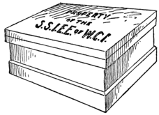
Fig. 2. The Black Walnut Box.
years. I unlocked
the box and
brought to light
the “Records and
Chronicles of the
Society for the
Scientific Investigation,
Exploration and Exploitation
of Willow
Clump Island.”
For hours I pored over those pages,
carried back to the good old times we used to have as boys
along the banks of the Delaware River, until I was brought
sharply back to the present by the sound of the dinner bell.
It seemed that the matter contained in those “Chronicles”
was too good to be kept locked up in an old trunk. Few
boys’ clubs ever had such a president as Bill, or such a wonderful
bureau of information as Uncle Ed. For the benefit
of boys and boykind in general, I decided then and there to
publish, as fully as practicable, a record of what our
society did.
Christmas Vacation.
This was how the society came to be formed. Bill, whom I met at boarding-school, was an orphan, and that’s why he 20 was sent to boarding-school. His uncle had to go down to Brazil to lay out a railroad, I believe, and so he packed Bill off to our school, which was chosen in preference to some others because one of the professors there had been a classmate of Uncle Ed’s at college. Bill roomed with me, and naturally we became great chums. When Christmas time came, of course I invited him to spend the holidays with me. My home was situated in the little village of Lamington, on the Jersey side of the Delaware River. Here we arrived late at night on the Saturday before Christmas. A cold wind was blowing which gave promise of breaking the spell of warm weather we had been having, and of giving us a chance to try our skates for the first time. True to our expectations, the next day was bitterly cold, and a visit to the canal which ran along the river bank, just beyond our back fence, showed that quite a thick skim of ice had formed on the water. Monday morning, bright and early, found us on the smooth, slippery surface of the canal. “Us” here includes, in addition to Bill and myself, my two younger brothers, Jack and Fred, and also Dutchy Van Syckel and Reddy Schreiner, neighbors of ours. It was the custom at the first of December every year to drain out most of the water in the canal, in order to prevent possible injury to the canal banks from the pressure of the ice. But there was always a foot or two of water covering the bottom of the canal, and this afforded a fine skating park of ample width and unlimited length, while the high canal banks on each side protected us from the bitter wind that was blowing. 21 Toward noon, however, the wind shifted and swept at a terrific rate down the narrow lane between the canal banks. We could scarcely make headway against the blow. It was too much for Bill, who wasn’t as used to skating as we were. He sat down in a sheltered nook and commenced to think. When Bill sat down to think it always meant that something was going to happen, as we soon learned.
“Say, Jim,” said he to me, “have you got any canvas up at the house?”
“No,” I replied. “What do you want it for?”
“I want to rig up a skate sail. If you have an old sheet, that will do just as well.”
“Well, I guess I can find you an old sheet. Do you think you can make one?”
“Sure thing,” answered Bill, and off we went to the house, where I received my first lesson on the practical genius of my chum.
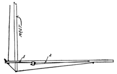
“Bill’s” Skate Sail.
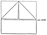
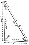
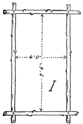
22The old sheet which Mother furnished us was laid out on
the floor and two corners were folded over to the center, as
shown in the drawing, making a triangle with base 7 feet
long and sides each about 4 feet 6 inches long. The surplus
end piece was then cut off, and a broad hem turned and
basted all around the edges of the triangle. Bill wanted
to work the sewing machine himself, but Mother was
afraid he would break something, so she sewed down
the hem for us. Then, under Bill’s supervision,
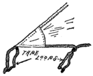
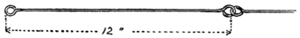
Fig. 4. The Tape Tie Strings.
she re-enforced the corners by
sewing on patches of cloth. Along
the diagonal a strip of heavy tape
was sewed, leaving loops at intervals,
which afterward were
cut and provided means for tying
the sail to the mast. Tie
strings of tape were
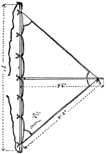
Fig. 5. “Bill’s” Sail Complete.
also sewed at the corners, as shown in the
illustration, and then a trip was made to
the garden in search of suitable
spars. A smooth bean pole of
about the right weight
served for the mast,
and another stick
with a crotch at
one end served as the
boom or cross-spar. The
spars were cut to proper length,
and the sail was then tied on, as
illustrated, with the crotch of the
cross-spar fitted against and tied to
the center of the mast. A light
rope, long enough to provide plenty
23
of slack, was tied to the ends of the mast to assist in guiding
the sail when in use. In the meantime I had procured
another sheet from one of our neighbors, and Bill helped me
make a sail for myself. It was not until long after dark
that we finished our work.
Willow Clump Island.
The next day we tried the sails and it didn’t take me very long to learn how to steer the device. The wind had changed again and this time blew up the canal. We took the line of least resistance, and went skimming up the ice lane like birds for several miles before we realized how far we were getting away from home. As we rounded a bend in the canal, much to my astonishment, I saw just before us the bridge at Raven Hill, eight miles from our town. We started to go back, but the wind was too strong for us, and there wasn’t much room in which to do any tacking; nor could we make any progress when the sails were folded. I began to get extremely tired and rather exasperated at Bill for not having thought of the return trip before he led me such a hot pace up the canal. But Bill was getting tired, too.
“Look here, Jim,” he said, “we haven’t covered a mile, and I’m worn out.”
“Why in thunder didn’t you think of this before we started?” I returned.
“How much money have you with you?” was the reply.
“What’s that got to do with it?”
“I’ll tell you in a minute. How much have you?”
24A careful search of my dozen odd pockets netted the sum of twenty-seven cents.
“I have fifty-nine,” said Bill, “and that makes eighty-six altogether, doesn’t it? Isn’t there a railroad depot near here?”
“There is one at Raven Hill, and the next is at Lumberville. That is about eleven miles from home.”
“Well,” said Bill, “at three cents each per mile that would amount to sixty-six cents. Let’s sail on to Lumberville and then take the train back.”
On we sped to Lumberville, only to find that the next train was not due until noon, and it was now just half past ten.
Time never hung heavy on our hands. Out on the river we espied an island. I had heard of this island–Willow Clump Island, it was called–but had never been on it; consequently I fell in with Bill’s suggestion that we make it a visit. Owing to the rapids which separated the island from the Jersey shore, we had to go up stream a quarter of a mile, to where a smooth sheet of ice had formed, over a quiet part of the river; thence we sailed down to the island along the Pennsylvania side.
“What a capital island for a camp,” cried Bill, after we had explored it pretty thoroughly. “Have you ever been out camping?”
I had to confess I never had, and then Bill gave me a glowing account of his experiences in the Adirondacks with his uncle the year before, which so stirred up the romance in me that I wanted to camp out at once.
25“Shucks!” said Bill, “We would freeze in this kind of weather, and besides, we’ve got to make a tent first.”
We then sat down and made elaborate plans for the summer. Suddenly the distant sound of a locomotive whistle interrupted our reveries.
“Jiminy crickets!” I exclaimed. “That’s the train coming through Spalding’s Cut. We’ve got to hustle if we are to catch it.”
We were off like the wind, and a merry chase brought us to the Lumberville depot in time to flag the train. We arrived at Lamington at half past twelve, a trifle late for dinner, rather tired and hungry, but with a glowing and I fear somewhat exaggerated account of our adventure for the credulous ears of the rest of the boys.
Organizing the Society.
The camping idea met with the hearty approval of all, and it was decided to begin preparations at once for the following summer. Dutchy, whose father was a member of a geographical society, suggested that we form a society for the exploration of Willow Clump Island. By general acclamation Bill was chosen president of the society, Dutchy was made vice-president, Reddy was elected treasurer, and they made me secretary. It was Dutchy who proposed the name “The Society for the Scientific Investigation, Exploration and Exploitation of Willow Clump Island.” It was decided to make an expedition of exploration as soon as we could make skate sails for the whole society.
The duties of the secretary, as defined in the constitution which Dutchy Van Syckel drew up, were to keep a record of all the acts of the society, the minutes of every meeting, and accurate detailed descriptions of all work accomplished. Therefore, while the rest of the society was busy cutting up old sheets, levied from the surrounding neighborhood, and sewing and rigging the sails under Bill’s direction, I, with pad and pencil in hand, took notes on all the operations.
The Double Swedish Sail.
Bill evolved some new types of sails which differed materially
from the type described in the first chapter. One
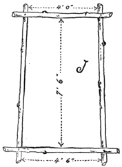
was a double sail–“the kind they use in Sweden,” he explained.
One of the
sheets which the foraging
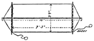
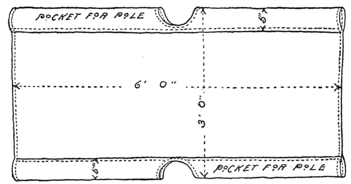
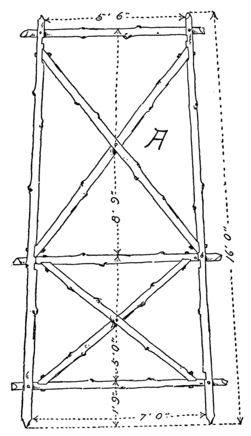
Fig. 6. Dimensions of Double Swedish Sail.
N. B.–The mark (') means feet and (") means inches.
party brought in
was extra large; it
measured approximately
two yards and
a half square. This
was folded on itself,
27
making a parallelogram seven feet six inches long and three
feet nine inches wide. The sheets we had were all rather worn
and some were badly torn, so that we had to make our sails
of double thickness, sewing patches over

Fig. 7. Halyards Looped onto Pole.
the weak spots. A broad hem was turned
down at each end, and heavy tape was
sewed on, leaving loops as before, to attach
them to the
spars. This reduced the length
of our sail to seven feet three
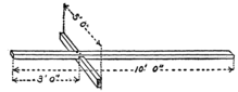
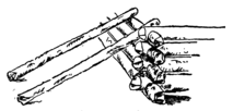
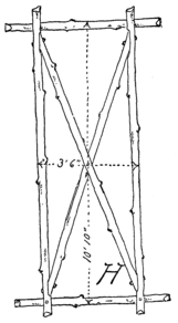
inches. The end spars were spaced apart by a light pole about ten feet long, to which they were
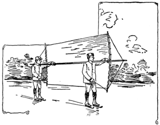
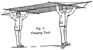
Fig. 8. The Double Swedish Sail.
tied at the points of intersection. The spars were also braced
by halyards looped over the ends of the pole in the manner
indicated in the drawing (Fig. 7). It took a crew of two
boys to manipulate this sail. In use, the pole of the rig was
carried on the shoulders, and the sail was guided by means
of ropes attached to the lower corners of the vertical spars.
28
These ropes in nautical
language are
called “sheets.”
The boy at the rear
was the pilot and
did the steering, because
his position behind the sail gave him an unobstructed
view in all directions. When changing tack the sail was
lifted overhead to the other side of the crew.
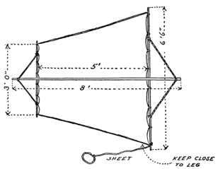
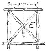
The Single Swedish Sail.
Another sail of similar form, but for use of one boy only, is shown in Fig. 10. This had a height of six and one-half feet at the forward end and three feet at the rear; and its length was five 29 feet. This sail was very satisfactory in light winds, owing to its great area. In use we found that it was very important to keep the lower edge against the leg, as indicated by the arrow. The rig was manipulated just like the double Swedish sail, lifting it over the head when it was desired to change tack.
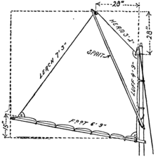
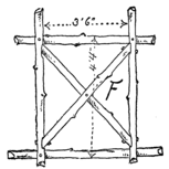
The Lanteen Sail.
The lanteen sail we
found to be a very good
rig. It was made in
the form of a triangle,
measuring
eight feet on one
side, seven and
one-half feet on
another side and
six and one-half
feet on the third.
The six and one-half
foot side
was secured to a
boom, and the seven and one-half
foot side to a yard. The yard and
boom were hinged together by a leather strap nailed on as
shown in Fig. 12, and to this hinge a rope was attached, which
served as a sheet. These spars were secured to a mast erected
perpendicularly to the boom and intersecting the yard a little
above its center. We had had some trouble with the first
30
sails we made in keeping the base of the sail against the
body, and to overcome this difficulty Bill proposed tying the
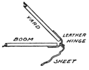
Fig. 12. Hinge for Spars.
bottom of the mast to the leg. This was
a rather risky thing to do, as we learned
later, for in case of accident it
would be difficult to get clear of
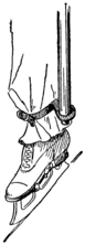
Fig. 13. Leather Mast Step.
the sail. It
was Reddy
who finally
solved the
problem by rigging up a step for the mast.
It consisted of a leather tag tied to the leg,
and provided with a hole into which the
bottom of the mast was
fitted. To prevent the
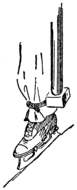
Fig. 14. Wooden Mast Step.
mast from slipping too
far into the step the lower
portion of it was whittled
down, leaving a shoulder
which rested on the leather. Bill later devised
another step, which consisted of a
wooden block (Fig. 14) strapped to the leg
and formed with a shallow socket to receive
the end of the mast.
The Danish Sail.
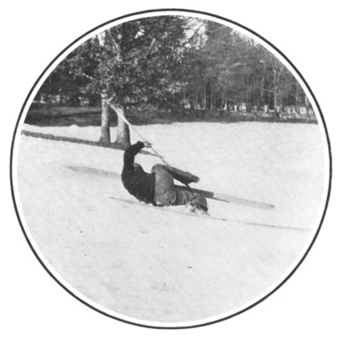
31But the most satisfactory sail we found to be the Danish
sail, though it was not until we had served quite a long
apprenticeship and
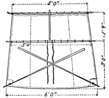
Fig. 15. The Danish Sail.
sustained many
pretty bad falls that
we mastered the
art of manipulating
these sails
properly. Our
ideas on this sail
were obtained
from a French illustrated
paper
which Dutchy
Van Syckel picked up in his father’s library. This sail was
formed with a topsail so arranged that it could be lowered
when the wind was too strong. The dimensions of the sail
as we made it are given in the drawing
(Fig. 15). The top of the sail
was lashed to a spar, which
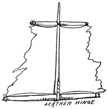
Fig. 16. Topsail of the Danish Rig.
was connected by a short
stick to another spar tied to
the mainsail about eighteen
inches lower down.
The sail was strengthened
with an extra
strip of cloth along
the lower spar,
and the tie strings
were applied in
the usual way. The connecting stick, or topmast we may
call it, was hinged to the lower spar by means of a short piece
of leather strap, which was passed round the spar in the
form of a loop and its two ends nailed to the bottom of the
topmast. The topmast extended above the upper spar a
short distance, and to this we fastened the flag which our
society had adopted. A couple of strong cords were secured
to the center spar to provide for fastening the sail onto the
skater. Tied to the lower corners of the mainsail were two
sticks which were used for guiding the sail when in flight.

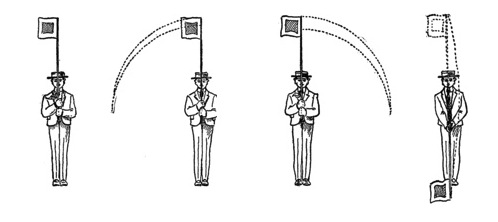
Fig. 17. Before the Wind. Fig. 18. Topsail Lowered. Fig. 19. Skating against the Wind. Fig. 20. On the Port Tack.
33The different methods of sailing with this rig are shown in Figs. 17-20. When sailing with the wind the skater would stand very erect, bending backward in proportion as the wind blew fresher. By inclining the sail in one direction or the other, the skater could tack to port or starboard. When moving against the wind by skating in the usual way, the body was bent forward in such manner that the sail lay horizontal, so that it would not offer a purchase for the wind.
Bat’s Wings.
One more sail deserves mention. It was Bill’s idea, and it
came near to ending his career the first day he tried it. It
had no spars at all, but was merely a strip of cloth of somewhat
triangular shape. The upper side was tied to the
head, and the two corners to the wrists, while the lower
portion was tied to the ankles. This converted him into a
huge white-winged bat. Bill had to try it at once, even
though the rest of the sails were not finished, and a very
34
comical spectacle he made as he flapped his wings in his
endeavors to tack. When the wind was too strong for him
he had merely to drop his arms and thus lower sail. At
length he became tired of holding his arms out at full length,
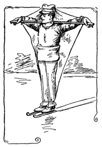
Fig. 21.
and I got him a stick
to put over his shoulders
and rest his arms
on. But that stick was
Bill’s undoing, for
coming around a sudden
bend in the canal
he caught the full
force of the wind,
which knocked him flat
on his back before he
could disentangle himself
from the stick and
lower sail. It took us
some time to bring him
back to consciousness,
and a very scared lot of boys we were for a while. However,
the lesson was a good one, for after that we were very
cautious in experimenting with sails that had to be tied on,
such as the Danish rig and the lanteen rig, before Reddy invented
the mast step.
It was not until the day after Christmas that the sails were all completed, but then there was scarcely any wind blowing and we could not attempt the expedition to the island.
The next day, Sunday, it began to snow, and we realized that our chance of skating up to Willow Clump Island was spoiled. All the afternoon it snowed, and the next morning we woke to find the ground covered to a depth of eight inches and snow still falling. But who ever heard of a boy complaining because there was snow on the ground? Here were new difficulties to overcome, new problems to solve, and new sports provided for our amusement. There was no disappointment shown by any of the members of the S. S. I. E. E. of W. C. I., as they met in the woodshed immediately after breakfast to discuss proceedings for the day. There seemed to be but one way of reaching the island, and that was by means of snow shoes. Bill had only a vague idea of how snow shoes were made.
Chair Seat Snow Shoe.
The first pair was made from a couple of thin wooden chair seats which we found in the shed. They proved quite serviceable, being very light and offering a fairly large bearing surface. The chair seats were trimmed off at each side to make the shoes less clumsy, and a loop of leather was 36 fastened near the center of each shoe, in which the toe could be slipped. This shoe possessed the disadvantage of being too flat and of picking up too much snow when used.
Barrel Stave Snow Shoe.
Another pair of shoes was made from barrel staves. At first one stave was made to serve for a shoe, but we found that two staves fastened together with a pair of wooden cleats were much better. Jack was the proud inventor of these shoes and insisted that they were far more satisfactory than the elaborate ones which were later devised.
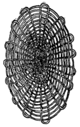
Barrel Hoop Snow Shoe.
Now that Jack had shown his ingenuity, Fred thought it was his turn to do something, and after mysteriously disappearing for the space of an hour we saw him suddenly come waddling back to the shed on a pair of barrel hoops covered with heavy canvas. He had stretched the canvas so tightly across the hoops that they were bent to an oval shape. It was claimed for these shoes, and with good reason, that they were not so slippery as the 37 barrel stave shoe, for they permitted the foot to sink slightly into the snow.
After dinner, Dutchy came back with a book of his father’s, a sort of an encyclopedia in which several different kinds of snow shoes were illustrated. Reddy, whose father owned a sawmill, volunteered to provide us with strips of hickory from which to make the frames.
The Sioux Snow Shoe.
The Sioux snow shoe was the first type we
tackled. Two strips of hickory 4 feet long
and 3/4 inch square in section, were bent
over a pair of spreaders and securely
fastened together at each end. The
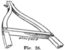
Fig. 26. Frame of the Sioux Shoe.
spreaders were about 12
inches long and located
about 15 inches apart.
They were
notched at the
ends, as shown in
Fig. 26, to receive
the side strips, which were not fastened
together until after they had been nailed to the spreaders.
We found that the most satisfactory way of fastening together
the ends of the hickory strips was to bolt them together.
When the frame was completed, we began the
tedious process of weaving in the filling or web of the snow
38
shoe. First we cut notches in the edges of the spreaders,
spacing these notches an inch apart. Then we procured
several balls of heavy twine at the corner store. Tying one
end of the cord to the right side stick about three inches
below the forward spreader, we stretched a strand down to
the notch at the left end of the lower spreader. The strand
was drawn taut, and after making several twists around it
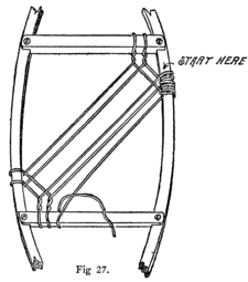
Fig 27. Web of the Sioux Shoe.
the cord was tied to the left
side stick three inches above
the spreader. From
this point the cord
was stretched to the notch at
the right end of the upper
spreader, twisted several
times and brought back to the
starting point. The cord was
now wrapped around the side
stick for a space of about an
inch, and then carried down
to the second notch on the
lower spreader, whence it was
woven through the other two
strands and tied about the left side stick about four inches
from the spreader. Thus the weaving continued, passing
the cord alternately over and under any cross strands encountered.
In order to make the left side correspond with
the right, a separate cord was wound around it, filling up the
space between the strands of the web. The filling above
39
and below the spreaders could not be so methodically done,
but we managed to weave the strands quite neatly with about
the same mesh as used at the
center. To facilitate the weaving
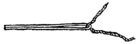
Fig. 28. Weaving Needle
we improvised a rough needle
of a piece of wire. The latter
was bent double to receive the cord which was wedged in between
the two arms of the needle.
The Iroquois Shoe.
But the best snow shoe we made was the Iroquois shoe.
The frame of this shoe was made of hickory strips of the
same width and thickness as used in the Sioux shoe, but
Fig. 29. Bending the Hickory Strips.
8 feet long. The strips were bent in a loop and the ends
were bolted together. How to bend the wood without breaking
it seemed a very difficult problem. Wood, we knew,
could be easily bent without
breaking if boiled or
steamed for a while; but
we had nothing large
enough in
which to boil a
strip of wood
8 feet long.
Bill hit upon
the plan of
wrapping the stick
with burlap and
40
then pouring boiling water on it until it became sufficiently
soft to bend easily. An old oats-sack was cut up into strips
and wound onto the hickory sticks for a distance of 18
inches at each side of the center. We then repaired to the
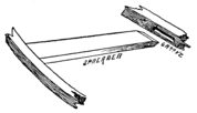
Fig. 30. Frame of Iroquois Shoe.
kitchen to do the steaming. The hickory stick was held over
a large dish-pan filled with boiling water, and from this we
dipped out the water and
poured it slowly over the
burlap wrapping of the
stick. After a little of this
treatment the stick was sufficiently
steamed to permit
of bending to the required shape. The ends
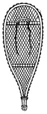
Fig. 31. Iroquois Snow Shoe.
were then firmly secured by means of bolts
passed through bolt holes which had been
previously drilled. The frame was completed
by fitting the spreader sticks in place,
after which it was laid away to dry. When
the frame was perfectly dry we started
weaving the web. In this case, however,
instead of cord we used cane strips, which
we had bought from a chair caner. This
necessitated drilling holes in the side sticks
to receive the cane strips. The web consisted
of strands crossing each other diagonally,
as illustrated. Our second pair
of Iroquois snow shoes was made with a web of rawhide
which we bought from a hardware store at Millville.
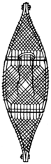
The Ainu Snow Shoe.
41One of the snowshoes described in the book was very much
like Fred’s barrel-hoop snow shoe in appearance. According
to the description, it was a type used by the Ainus, a peculiar
people living in the cold northern islands of Japan. As the
shoe seemed quite simple and rather unique, we thought we
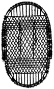
Fig. 32. Ainu Snow Shoe.
would make one like it. Two hickory
strips each 4 feet long were bent to a
U-shape and lashed together, forming
an oval about 2 feet 6 inches long by 18
inches wide. The frame was held to
oval shape by tying the sides together.
Then the filling was woven in, running
the strands diagonally, as shown in
Fig. 32.
We had excellent weather for snow shoes after that snowstorm. A thaw followed by a cold spell caused a thick crust to form on the snow which would nearly hold us up without the aid of our snowshoes. We were rather awkward with those shoes for a while, trying to keep them clear of each other, and we found it particularly hard to turn sharply without causing one shoe to run foul of the other. But with a little practice we soon felt quite at home on them. In order to prevent cutting the web with our heels, we found it necessary to wear rubbers.
42Our vacation came to an end before we were prepared for
the expedition to Willow Clump Island. But before leaving
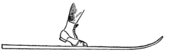
Fig. 33. The Norwegian Ski.
the subject on snow shoes,
two more shoes remain to
be described, namely the
Swiss snow
shoe and the
Norwegian
ski. The Swiss shoe was made during the summer and the
ski during the following winter.
The Norwegian Ski.
The Norwegian ski was made of close-grained wood, 1
inch thick, 3-1/2 inches wide and 6 feet long. About 18
inches from the forward end the wood was planed down to
a thickness of 1/4 of an inch. This end was placed in the
dish-pan of boiling water, and in a short time it was pliable
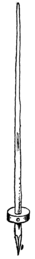
Fig. 35. The Ski Stick.
enough to permit of bending. It was secured
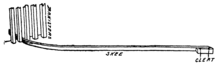
Fig. 34. Bending the Ski.
in the proper bent position by slipping the toe
end of the shoe between
the banisters
on the back porch
and nailing a cleat back of the heel end. When the ski was
perfectly dry the toe strap was nailed on just back of the
balancing point, and also another strap, to be secured about
the ankle. Then a cleat was nailed onto the ski to fit against
the heel of the shoe. In use we found it best to cut a groove
43
in the bottom of the ski, so as to give us a better
grip on the snow in climbing up hills. With the
skis we had to use short poles or “ski sticks” to assist
in starting, stopping and steering when coasting.
The ski stick was a bean pole provided with a wooden
block near the lower end, to prevent it from being
forced too far through the snow.
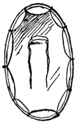
The Swiss Snow Shoe or Swamp Shoe.
The Swiss shoe was made primarily to assist us in exploring some boggy land a short distance up the river from our island. The original swamp shoes were made from the bottoms of two old baskets, and they worked so admirably that it was decided to equip the whole society with them. Uncle Ed, when told about them, informed us that that was the kind of snow shoe used in Switzerland. Of course, we could not afford to destroy a pair of baskets for each member of the club, and so we had to weave the shoes from the willows which grew on the island.
We had a farewell meeting of the society the evening before Bill and I had to return to boarding-school. At this meeting plans were made for the Easter vacation. We also considered the matter of getting parental permission for our summer outing. So far we had been afraid to breathe a word of our plans outside of the society, since Fred had said something about it in the presence of Father and had been peremptorily ordered to banish all such hair-brained, Wild West notions from his head. We realized from that incident that the consent of our parents would not be so very easily obtained. But Bill came forward with a promising suggestion. He would write to his Uncle Ed and see if he couldn’t be persuaded to join the expedition. At first we demurred. We didn’t want a “governor” around all the time. But Bill assured us that his uncle was “no ordinary man”; that he would not interfere with our plans, but would enter right into them and give us many valuable pointers. Though not by any means convinced, we told him to go ahead and invite his uncle, as that seemed about the only means of winning over our fathers and mothers. The society was then adjourned until our Easter vacation began, each member 45 promising to earn and save as much money as he could in the meantime to buy the materials for a tent and provisions for the summer outing.
Word From Uncle Ed.
Bill’s letter to Uncle Ed was answered as quickly as the mail could travel to Brazil and back. Uncle Ed heartily approved of our plans, and said that he would be delighted to join the expedition. He could not be on hand before the 1st of July, but that would give us plenty of time to make all necessary preparations. He told us not to worry about gaining the consent of our parents. He would write to them and see them all personally, if necessary to win their approval.
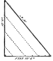
The Canvas Tent.
46When at last spring arrived and we returned to Lamington
on our Easter vacation, quite a sum of money had been
collected, nearly $15.00, if I remember rightly; at any rate
plenty to buy the materials for a good-sized tent and leave a
large surplus for provisions,
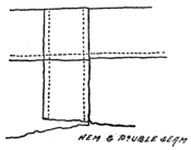
Fig. 38. The Sail Stitch.
etc. Bill figured out on paper
just how much canvas we
would need for a tent 7 feet
wide by 9-1/2 feet long, which
he estimated would be about
large enough to hold us.
It took 34 yards, 30
inches wide. Then we
visited the village store to make our purchase. Canvas we
found a little too expensive for us, but a material called drill
seemed about right. It cost ten cents a yard, but since we
wanted such a quantity of it the price was reduced to a total
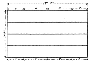
of $3.00. We repaired to the attic to lay out the material.
First we cut out four lengths of 5 yards and 26 inches
each. The strips were basted together, lapping the edges
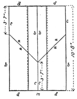
Fig. 39. Cutting out the Door Flaps.
1 inch and making a piece 17 feet 2 inches long by 9 feet 9
inches wide. Mother sewed the breadths together on the
machine, using a double seam, as in sail making; that is, two
parallel rows of stitching were sewed in, one along each
overlapping edge, as shown in Fig. 38. A 1-inch hem was
47
then turned and sewed at the
ends of the goods, so that the
piece measured exactly 17 feet
long. It served for the roof
and side walls of the tent.
Our next operation was to cut
three strips 11 feet long, and
sew them together with a
double seam as before. This
piece was now slit along the
center line m, Fig. 39, making
two lengths 3 feet 8
inches wide. The strips were
then cut along the diagonal lines a a, forming the
end walls or doors, so to speak, of the tent. In sewing
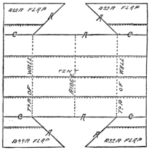
Fig. 40. Sewing on the Door Flaps.
on the door flaps we
started first at the
bottom of the side
c, sewing it to the
side edge of the
main piece, as shown
in Fig. 40, and running
the seam up for
a distance of exactly
3 feet 6 inches.
After all the door
strips had been
sewed along their c
edges the sewing was continued up the diagonal or a edges.
In cutting out the door pieces we had allowed 1 inch on each
side for hems and seams, so that the door pieces met without
lapping at the exact center of the main or body piece, that is,
48
at the peak of the tent.
Our next step was to fasten the necessary ropes and loops.
Ten 8-foot lengths of light rope were procured. These
were fastened at the top of the side walls, that is, 3 feet 6
inches from the ends of the main or body piece, one at each
corner and one on each seam. The cloth was
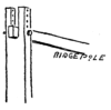
Fig. 41. Adjustable Ridge Pole.
strengthened at these points with
patches sewed on the inside. At
the bottom of the side walls we
sewed on loops of heavy tape.
These were spaced about 15 inches
apart. Along the b edges of the door pieces tie strings of
tape were fastened. A rope 15 feet long was attached to
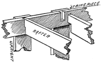
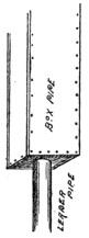
the peak at the front and at the rear of the tent. The front
and rear posts of the tent were made from scantlings measuring
2 by 4 inches, which were procured from Mr. Schreiner’s
lumber yard. They were planed smooth and sawed off to a
length of 7 feet 6 inches. A slot was cut in the end of each
stick to a depth of 6 inches and measuring slightly over an
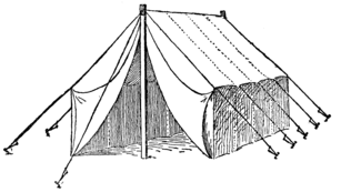
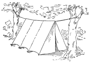
Fig. 42. The Tent Set Up.
inch in width. For the ridge pole a strip 1 inch thick, 2-1/2
inches wide and 10 feet long was secured. This was fitted
into the slotted ends of these posts, where it was fastened
by wooden pegs slipped into holes drilled through the ends
of the posts and the ridge pole. A number of these peg
49
holes were provided, so that if the canvas stretched the ridge
pole could be raised or lowered to prevent the walls from
dragging on the ground. We set up the tent in our back
yard to see if it was properly constructed. Twelve stakes
were required, ten for the sides and one for the ridge stays
at the front and rear. The side stakes were driven into the
ground at a distance of about 8 feet from the center of the
tent. First we tied the guy ropes to the stakes, but later we
found it much easier to secure them with tie blocks.
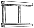
Tie Blocks.
These were made of wood 1/2 inch thick, 1 inch wide and
each measured 3 inches long. A hole was drilled into the
block at each end and through these holes the rope was
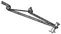
Fig. 44. The Wire Tie.
threaded. A knot in the rope then held the end from slipping
50
out. The loop between the two holes, or the bight, as
sailors would call it, was now slipped over the stake, and
the rope hauled tight by drawing up the tie block, as shown
in Fig. 43. A still later improvement consisted in making
ties of stout galvanized
iron wire, bent to the form
shown in Fig. 44. The
wooden ties were apt to
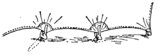
Fig. 45. Bottom of Tent Wall.
swell and split open when
exposed to the weather, while the wire ties could always be
relied upon.
The walls of the tent were held down along the bottom by railway spikes hooked through the tent loops and driven into the ground. Wooden pegs with notches to catch the loops would have served as well, but Dutchy happened to find a number of the spikes along the track and in his usual convincing manner argued that they were far better than pegs because their weight would hold the cloth down even if they were not firmly embedded in the ground.
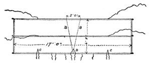
The Annex.
We were surprised to find out how small the tent was after it was set up. We could see at once that when we had put in all the stores and provisions we would need, there would not be room enough for six boys and a man to stretch themselves out comfortably in it. Bill had evidently made a miscalculation, but he suggested that we remedy the error by building an annex for our kitchen utensils and supplies.
51This gave us a two-room tent, which we found to be quite
an advantage. Twelve more yards of drill were bought and
cut into two strips, each 17 feet 2 inches long. The breadths
were then sewed together, and the ends turned up and
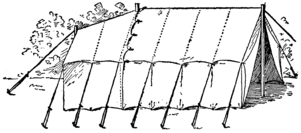
Fig. 47. The Annex Applied.
hemmed to make a piece 17 feet long and 4 feet 9 inches
wide. Tape loops were then sewed on as before, and ropes
were fastened on at the top of the side walls, that is, 3 feet
6 inches from the ends of the strips. We thought it would
be better to have a slanting ridge on the annex, so we cut out
a wedge-shaped piece from the center of the two strips, as
shown by dotted lines B B in Fig. 46. This wedge-shaped
piece measured 2 feet at the outer end of the annex, and
52
tapered down to a point at the inner end. The canvas was
then sewed together along these edges. Tie strings were
sewed to the inner edge of the annex and corresponding ones
were attached to the main tent a little ways back from the
edge, so that the two could be tied together, with the annex
lapping well over on the roof and side walls. A notch was
cut out of the peak of the annex, so that it could be tied
around the rear post of the tent, and notches were cut at
the top of the side walls to permit passing the cloth around
the wall ropes. Instead of supporting the ridge of the annex
on a ridge pole, we used the rear guy line of the tent, propping
it up with a scantling about 5-1/2 feet long.
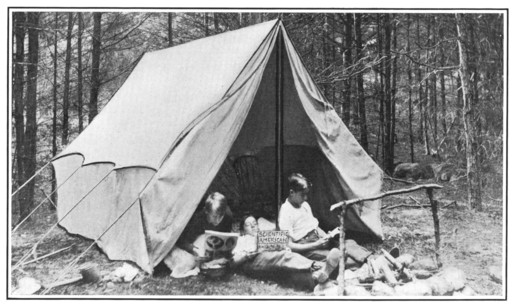
School closed on the 21st of June that year, just ten days before the expected arrival of Uncle Ed. The first thing we did was to set up our tent in the back yard and camp out so as to become acclimatized. It is good that we did this, for the very first night a heavy summer shower came up which nearly drenched us. The water beat right through the thin canvas roof of our tent. Had we been able to afford the best quality of canvas duck, such an occurrence would probably have been avoided. But we solved the difficulty by using a tent fly; that is, a strip of canvas stretched over the tent and spaced a short distance from it to break the fall of the rain drops.
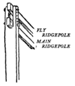
Tent Fly.
54Again we had to visit the village storekeeper; this time we bought out his whole remaining stock, sixteen yards of drill. This was cut into four-yard strips, which were sewed together as before and the ends turned up and hemmed. Tie strings were sewed to the ends of the strips so that the fly could be tied to the wall ropes of the tent. At the ridge the fly was supported about six inches above the tent rope by a second ridge pole held by pegs in the top holes of the tent posts.
Provisions and Supplies.
The ten days before Uncle Ed arrived were busy indeed. We had to gather together the necessary provisions and supplies. Our personal outfits were very simple. Each member supplied himself with a change of underwear, a bathing suit, a blanket and a toothbrush. A single comb and brush served for the entire society, and was used on Sundays, the only day we really dressed up. All the rest of the time we lived in our bathing suits, except, of course, on cold rainy days. Our kitchen outfit consisted of a large cooking pot, two kettles, a frying pan, a coffee pot, a small oil stove, a half-dozen each of plates, cups, saucers, knives and forks, a dozen spoons, two tablespoons, and, in addition, several large 55 plates and bowls for pantry use. We also took with us a dish-pan and several dish-towels. For our larder we collected the following: A bag of flour, ten pounds of sugar, two pounds of salt, three pounds of coffee, four pounds of oatmeal, four pounds of butter, two pounds of lard, six pound of beans, six pounds of rice, three pounds of bacon, six cans of condensed milk, a dozen eggs, box of pepper, and several jars of canned peaches and pears, and also a half dozen glasses of jelly.
It was Dutchy who suggested that we have a chicken yard, in connection with our camp, to supply us with fresh eggs. It was a capital idea, and by the dint of some coaxing we managed to secure the loan of a half dozen hens and a rooster.
Our miscellaneous list included a spade, pick and shovel, an ax, a hatchet, two large pails, a barn lantern, a can of kerosene, a dozen candles, a cocoa box filled with matches, a pair of scissors, needles, buttons, pins and safety pins, a spool of white and another of black cotton, fishing tackle, a roll of heavy twine, a coil of rope, and a set of dominoes and checkers. But most important of all was a chest of tools belonging to Reddy. These were all collected when Uncle Ed arrived. Dutchy also contributed a large compass, which we found very useful later on, for surveying the island.
Crossbow.
Reddy had a shotgun which he wanted to bring along, but my father, and Dutchy’s as well, wouldn’t let us go camping 56 if there was to be any gunpowder along, so we had to leave it behind. Of course we didn’t miss it at all when we got to the island, because there was so much else to do; but we all agreed with Dutchy, that “it wouldn’t be no sort of a scientific expedition without takin’ a gun along.” As a substitute I suggested a bow and arrow. They all laughed at such a “kiddish” idea; all but Bill, I mean.
“It ain’t such a bad notion,” said he, “only a crossbow
would be better. I’ve seen them made out of umbrella
ribs so they’d shoot like greased lightning.” Of course we
had to have one of these wonderful weapons. Down in the
ash heap we found two broken
umbrellas with 27-inch ribs. Bill
selected ten good ribs, from which
he wrenched off the spreaders with
a pair of pliers. The ribs were
then bound together by winding

Fig. 51. The Trigger.
stout twine around them. The winding was very evenly
and closely done, so that the cord completely covered the
ribs, making a solid rod of spring steel. But before winding
we had laid in between the ribs a piece of heavy twine, to
which the bowstrings could be tied after the bow was all
wound. The stock of our crossbow was cut out of a board
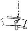
Fig. 52. The Trigger Set for Firing.
of soft wood 1 inch thick to as near the shape of a gun as
we could get it. A hole was drilled through the muzzle
end to receive the bow, and then the bowstring was tied fast.
Along the upper edge of the barrel a V-shaped channel was
cut. The channel was not very deep, only enough to receive
57
a tenpenny nail with the head projecting half-way above the
sides. A notch was cut across the barrel, through this channel,
at the trigger end, and a trigger made of heavy iron wire,
bent to the shape shown in Fig. 51,
was hinged to the gun by a bolt
which passed clear
through the stock and
through both eyes of the
trigger. By using two nuts on the bolt,
and tightening one against the other,
they were prevented from working loose
and coming off. When we wanted to fire the gun the bowstring
was drawn back, and held by slipping it into the notch,
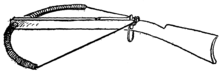
Fig. 53. The Umbrella Rib Crossbow.
and a nail was laid
in the channel with
its head against the
bowstring. Then, on
pulling the trigger, the
bowstring was lifted out of the notch, and sent the nail off
sailing. The long-grooved barrel insured a
very good aim.
Megaphone.
Another device we made in preparation
for the expedition was a megaphone.
A sheet of light cardboard 30 inches
square was procured. At the center of
one edge a pin was stuck into the
58
cardboard, then a piece of stout thread was looped over
the pin and the two ends were knotted together just
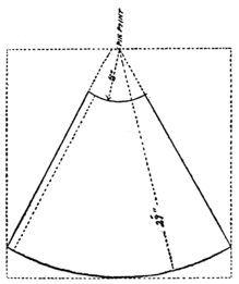
Fig. 55. Layout of the Megaphone.
5 inches from the
pin. Another
knot was also
made 29 inches
from the pin.
Now, with a pencil
hooked into
the loop, and resting
first against
the inner knot
and then against
the outer one, two
arcs were drawn
on the paper, one of 5-inch radius and the other of 29-inch
radius. A line was now drawn from the pin to the point
where the longer arc met the right hand edge of the paper,
and a dotted line was drawn from the pin to a point

Fig. 56. Brass Fastener.
1-1/2 inches from the edge at the
other end of the arc. From a point
1 inch to the left of the pin we
then drew a line to the left end of
the arc. With a scissors we cut the cardboard
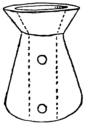
Fig. 57. The Mouthpiece.
along the arcs and straight lines, all
but the dotted line, leaving a piece of the
shape shown in Fig. 55. This piece was
rolled into a cone with the right edge
59
lapped over the left edge and lying against the dotted line.
In this position it was held by means of several brass fasteners
of the kind shown in Fig. 56.
A mouthpiece was formed out of a block of wood in which a large hole had been drilled. The block was then cut away until the walls were quite thin. The hole was reamed out at the top, as shown in Fig. 57, and the outer surface was tapered so that the small end of the megaphone would fit snugly on it.
We planned to reach our camping grounds by way of the canal, and had provided for that purpose a large scow, which we expected to tow up to Lumberville and drag over to the river.
The Scow.
Our scow was made as follows: Two 3/4-inch pine boards,
12 inches wide and 12 feet long, were selected from Reddy’s
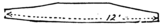
Fig. 58. Side pieces of the Scow.
father’s lumber pile. These were used for the side pieces
of the boat, and we tapered
them off at the end to a width
of 3-1/2 inches. This was done
by making a straight cut from the end to a point three feet
back along the edge of the board and then rounding off the
edge with a draw-knife. When one board had been shaped,
it was used as a pattern for the other, which was thus cut to
exactly the same size. For the end pieces two strips, 4
inches wide and 2 feet 10-1/2 inches long, were sawed out of
60
a 1-inch board. Then for the bottom we procured a number
of 3/4-inch boards, 12 feet long and 8 inches wide, which
we cut into 3-foot lengths. At Bill’s suggestion, before
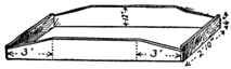
Fig. 59. Frame of the Scow.
nailing the parts together, we secured some strips of flannel,
which were saturated
with paint,
and laid between the
seams so as to make
the boat perfectly
water-tight. The side and end boards were then nailed
together, with the strips of flannel between, the side boards
overlapping the end boards, as shown in Fig. 59. After
planing down the end
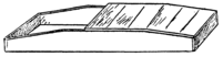
Fig. 60. Nailing on the Bottom.
boards until their
edges laid flush with
the edges of the side
pieces, the bottom
boards were nailed on, strips of cloth being inserted between
them, as well as along the edges of the side and end boards.
To brace the bottom a 3/4-inch board was placed at the
center, inside the boat, and bent down against the floor, to
which it was nailed with wire
nails. The nails were driven
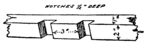
Fig. 61. Sockets for Rowlocks.
into the board from the outer
side of the boat and were
clinched inside. Along the upper edges of the side boards
two strips 2 inches wide and 1 inch thick were nailed. Two
notches were cut in the inner side of each strip before it was
61
nailed on. The notches were 1/2 inch deep, 1-1/2 inches wide,
3 inches apart and about 5-1/2 feet from the stern end. When

Fig. 62. Thole Pin.
the strips were nailed in place these notches formed sockets
to receive the rowlocks. A strip was also nailed
across the stern of the boat and formed with two
central notches, to receive the rowlocks for a
steering oar. This strip, however, was 3 inches
wide, and projected 1 inch above the end board,
so as to lie flush with the deck boards, which were
later applied. Six thole pins, 1/2 inch thick, 4-1/2
inches long and 2 inches
wide, were cut out of an
oak board. The lower
Fig. 63. Nailing on the Decks.
end of each pin was reduced
to a width of 1-1/2
inches for a length of 2
inches. The thole pins
were then fitted snugly in the notches. Two cleats, nailed
to the side boards inside, 7 inches below the upper edge,
served to support a seat board 1 inch thick and 2 feet 10-1/2
inches long. The aft edge of the seat was about 10 inches
forward of the rowlocks. The boat was completed by nailing
on a couple of deck boards at each end. The oars were
made of 2-inch pine boards, 5 feet long and 5 inches wide.
62
They were blocked out at Mr. Schreiner’s sawmill and then
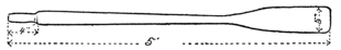
Fig. 64. The Oar.
shaped and smoothed down with a draw-knife and spoke-shaved.
They were 1-1/4 inches at the handle and 2 inches
immediately below, tapering down to a diameter of 1-1/4
inches at the top of the blade. The blades were 18 inches
long, 5 inches wide, and planed down to a thickness of 1/4
inch along the edges.
The morning of July 2d dawned bright and clear, but long before daybreak the members of the S. S. I. E. E. of W. C. I. were astir. The jolly red sun peeping over the eastern hills witnessed an unaccustomed sight. Six greatly excited boys were running back and forth from the barn to the canal, bearing all manner of mysterious bundles, which were carefully deposited in a freshly painted scow. Yes, all six of us were there.
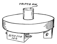
A Unique Alarm Clock.
We hadn’t expected to see Reddy Schreiner at such an early hour, for he was always a sleepyhead, and no alarm clock would ever wake him. But this was an exceptional day, and, besides, Reddy was quite an original chap. He had taken one of the borrowed roosters into his room the night before, and when, early in the morning, Mr. Chanticleer had mounted the footboard of the bed, flapped his wings and given vent to his opinion of a boy who persisted in sleeping at that late hour of the day, the noise was too much for even Reddy’s drowsy sensibilities.
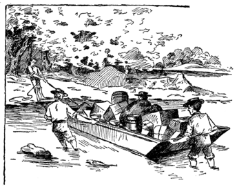
The Trip to the Island.
64Our scow was not large enough to carry all the things we had to take with us, but as Mr. Schreiner was going to take Uncle Ed up in his wagon, we left the rest of our luggage for him to bring along. We boys walked the eleven miles up the canal to Lumberville, towing the barge. It was a tiresome task; but we divided the work into two-mile shifts, two boys towing at a time and then each taking a mile ride as steersman in the boat. It was about noon when we arrived at Lumberville, and then we had to unload our boat before we could haul it out of the canal and down to the river. The 65 river on the Jersey side of the island was so shallow that we waded across, pushing the boat ahead of us. The current was too swift to permit of rowing, and it was rather hard for us to keep our footing. But we managed to reach our destination finally without any mishap. The island was thickly wooded, except for a small clearing where we landed. The first thing we did was to unpack our eatables, and Jack, the cook, soon had an appetizing pan of bacon and eggs sputtering on the kerosene stove.
Preliminary Exploration.
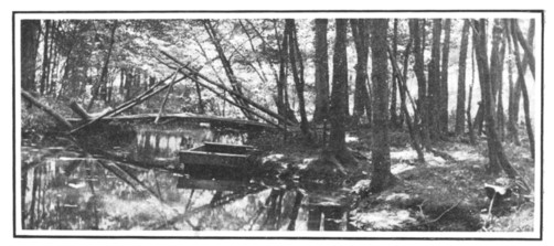
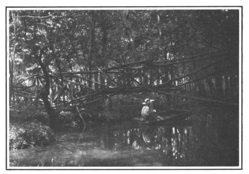
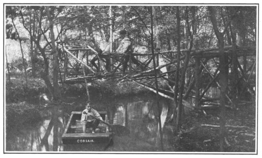
66As no better position offered at the time we pitched our tent in the clearing, pending a thorough search for a more suitable place elsewhere. Around the tent we dug a trench about a foot deep to prevent water from entering our quarters when it rained. It was about time for Uncle Ed and Mr. Schreiner to appear with the rest of our luggage, so we did not have time to do much exploring, but sauntered southward along the shore, always on the lookout for their arrival. About a quarter of a mile from the tent we came across the wreck of an old bridge, which had been washed down by some freshet. This was a great find, and served us many purposes, as will appear later.
While we were examining the wreck we heard a distant “halloa” from the mainland. There was Uncle Ed sitting on a pile of goods on the railroad bank looking for all the world like an Italian immigrant. We answered with a shout and scrambled back to the clearing. Then we ran splashing through the water, pushing the boat before us. It didn’t take us long to load up and carry him back to the island.
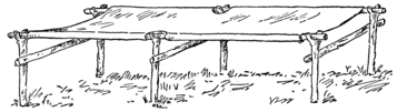
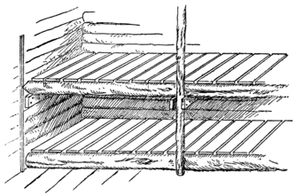
A Rustic Table.
Uncle Ed entered into our fun at once. He was as enthusiastic
as a boy over the surroundings, and when we told
him of the old bridge he started right off to investigate,
67
taking the ax with him. Soon he
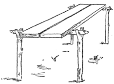
Fig. 67. The Rustic Table.
had pried off a number of the
planks, which we used
for a flooring to our
tent. Then he built
us a table out of four
forked sticks, driven
into the ground, and
supporting two
cross sticks, on
which a pair of
planks were laid.
The Small Filter.
“Well, now, boys,” said Uncle Ed, wiping the perspiration from his forehead, “I am as thirsty as a whale. Where do you get your drinking water? Is there a spring on the island?”
We told him that we used the river water.
“What, river water! That won’t do at all,” he cried.
“You’ll all have the typhoid fever. We must build a filter.
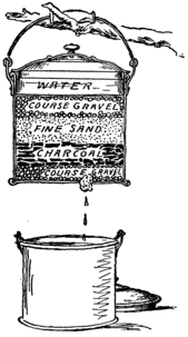
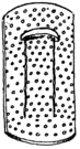
Fig. 68. The Small Filter.
I brought some charcoal with me for this very purpose.”
Taking one of our pails he broke a hole in the bottom of it and stuffed a sponge in the hole. A layer of small stones was then placed in the pail, over this a layer of broken charcoal with the dust carefully blown out, then a layer of clean sand, and finally a layer of gravel. Each layer was about two inches thick. The pail was suspended from a branch in a 68 cool place and proved an excellent filter, the water trickling out through the sponge being perfectly pure and sweet, no matter how dirty it had been when poured in; but the capacity of the filter was too small, and Uncle Ed said he would make us a larger one on the morrow if no spring was discovered in the meantime.
The sun was getting low in the west, and we therefore postponed the exploration of our island until the following day. We had been up since four o’clock that morning and had done some pretty hard work; so, immediately after supper, we turned in and, lulled by the murmuring of the river, were soon fast asleep.
The Barrel Filter.
Immediately after breakfast the next day we started out in
two parties to search the island. The only discovery of any
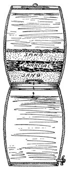
Fig. 69. The Barrel Filter.
moment was that made by Dutchy’s party, which found a
small island separated from ours by a narrow channel,
through which the water ran like a mill-race. No spring was
69
discovered, so Uncle Ed had to construct his large filter.
Bill and I went over to Lumberville in search of a couple of
cider barrels and a pailful of charcoal. The barrels were
placed one on top of the other after cutting a large hole in the
top of the lower barrel, and a smaller one in the bottom of the
upper one. The latter opening
was covered by an inverted
saucer. Over this we spread a
3-inch layer of coarse sand, then
a 2-inch layer of charcoal, a 4-inch
layer of clear, sharp sand,
and a 2-inch top layer of gravel.
The lower barrel was provided
with a faucet, through which we
could draw off the filtered water
as desired. In order to keep the
water cool we placed the filters
in a shady place near the river,
and piled up earth around the
lower barrel.
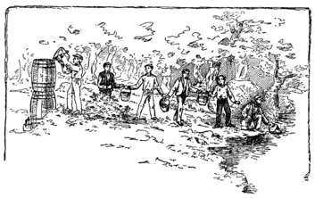
“Now, boys,” said Uncle Ed, “form in line there, and we will go through a fire drill.”
He arranged us about five feet apart in a line extending from the filter to the river. We had six pails, and these Dutchy filled one at a time, passing them up the line to Reddy, who emptied them into the upper barrel and then threw them back 70 to Dutchy to be refilled. Working in this way it did not take long to fill up the filter, and the burden of keeping the barrels full, instead of falling on one person, was shared alike by all.
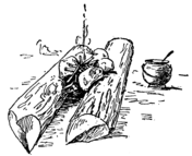
The Klepalo.
Our camp outfit was further augmented by a dinner call. We discovered the necessity of such a call on our very first day of camping. Dutchy was so excited by his discoveries of the morning that he started out alone in the afternoon to make a further search. The rest of us were lazy after the noon meal, and were lolling around taking it easy during the heat of the day, and discussing plans for the future. But Dutchy’s energetic nature would not permit him to keep quiet. He took the scow and waded with it against the strong current to the deeper and quieter water above the 71 island. Then he rowed a long way up stream. He was gone all the afternoon. Supper time came and still he didn’t appear. The sun was high, and I presume he didn’t realize how late it was getting. Finally, just at sunset, he came drifting down with the current, tired and hungry, and ready for a large meal. But we had finished our supper an hour before, and poor Dutchy had to be content with a few cold remnants, because the cook had declared he wouldn’t prepare an extra meal for a fellow who didn’t have sense enough to know when it was meal time.
Then it was that Uncle Ed bethought himself of the klepalo.
“You ought to have some sort of a dinner call,” he declared, “so that any one within a mile of camp will know when dinner is ready.”
“Did you ever hear of a klepalo? No? Well, I was
down in Macedonia a couple of years ago inspecting a railroad,
and I stopped off for the night at a small Bulgarian
village. The next day happened to be a Prasdnik, or
saint’s day, and the first thing in the morning I was awakened
by a peculiar clacking sound which I couldn’t make out. Calling
my interpreter I found out from him that it was a klepalo
for calling the people to church. The people there are too
poor to afford a bell, and so in place of that they use a beam
of oak hung from a rope tied about the center, and this beam
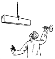
The Klepalo.
is struck with a hammer, first on one side, and then the other.
Sometimes an iron klepalo is used as well, and then they
strike first the beam and then the iron bar, so as to vary the
72
monotony of the call. I found that the wooden klepalo could
be heard for a distance of about one and a half miles over
land, and the iron one for over two miles. Now we can easily
make a wooden klepalo for use in this camp, and then if
Dutchy, or any of the rest of us, keep within a mile and a
half of camp there won’t be any trouble with the cook.”
So we built a klepalo, getting from Lumberville a stick of seasoned oak, 1-1/2 inches thick, 6 inches wide and 4 feet long. A hole was drilled into the stick at the center, and by a rope passed through this hole the beam was suspended from a branch overhanging the camp. Jack, the cook, regularly used this crude device to call the hungry horde to meals.
One of the first things we did after getting fairly settled in our new quarters was to make a complete survey of Willow Clump Island and its immediate surroundings. Our surveying instruments were made as follows:
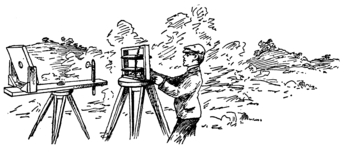
The Surveying Instrument.
Out of a 1-inch board we cut a base 15 inches long and
4 inches wide. In the center we sawed out a circular opening
of about 3 inches diameter and covered this at the bottom by
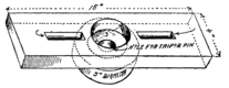
Fig. 71. Baseboard of the Surveying Instrument.
a circular piece 1 inch
thick and 5 inches in
diameter, thus forming
a socket in which our
compass fitted snugly.
A hole 1 inch in diameter
was drilled through the center of this circular piece
to receive the pivot pin of a tripod. Across each end of the
baseboard we secured a block 4 inches long, 2 inches wide
and 1 inch thick. A 1-inch sight hole was drilled through
each block at its center. A ring of cardboard, on which
74
Uncle Ed marked with radial lines the 360 degrees of the
circle, was placed over the compass socket, with the zero and
180 degree marks pointing toward the sight blocks. The
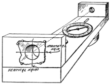
Fig. 72. Sighting Blocks on the Baseboard.
outer faces of the end blocks were now wet with mucilage
and a hair was stretched vertically across the center of each
sight hole. The hairs were then adjusted by
sighting through the holes and moving the
nearer hair sidewise until it was exactly in line
with both the zero and the 180 degree
marks on the cardboard.
Then a hair
was stretched horizontally
across the
center of each sight
hole. Great care
was taken to place
the hairs at exactly the same height above the baseboard.
To protect the hairs after they were adjusted, they were covered
with a piece of glass, which was secured in place by
tacks driven into the wood with their heads projecting over
the edges of the glass.
Spirit Levels.
From one of his pockets Uncle Ed produced two small bottles, the kind used for holding homeopathic pills. These he filled nearly to the top with water, corked them and wedged them into grooves cut lengthwise in the baseboard 75 at opposite sides of the cardboard ring. These grooves were filled with putty, and to make sure that the bottles were level with the baseboard the latter was floated on a bit of quiet water and the bottles were pressed down at one end or the other until the bubble within rested at the exact center.
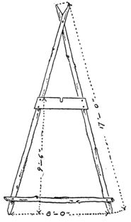
The Tripod.
The tripod head was
formed of a wooden disk 5
inches in diameter, with a
wooden pin projecting
from its center
adapted to engage
the hole in the circular
piece above
referred to. To the
bottom of the tripod head were nailed three blocks
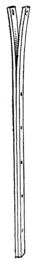
Fig. 74. The Tripod Leg.
2 inches long and 1 inch square in cross-section. The
tripod legs were made of light strips of wood, 3/8
inch by 1 inch by 5 feet long, which we secured from
one of the mills at Lumberville. Each leg was
formed of two of these strips, nailed securely together
to within 20 inches of the top. At the upper
ends the strips were spread to receive the blocks on
the tripod head. In this position they were held by
headless wire nails driven into the ends of the blocks
and fitting into holes drilled in the strips. For a
76
plumb line we
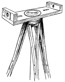
Fig. 75. The Surveying Instrument Complete.
tacked a cord to the
center of the tripod
head, and attached
a good-sized sinker to its
lower end. In connection with
this plumb line we occasionally
used a protractor consisting of
a semicircle of cardboard 5
inches in diameter, on which
the degrees of the circle
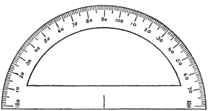
Fig. 76. The Protractor.
were marked off with radiating
lines, as illustrated in
Fig. 76. By holding the
straight edge of this protractor
against the base of
the tripod, and noting the number of degrees between the
90 degree mark and the plumb line, we could tell at a glance
at what angle from the horizontal the instrument was tipped.
Surveyor’s Chain.
77We made a surveyor’s chain of wire links, each 12
inches long, instead of 7.92 inches, which is the length of a
standard surveyor’s link. The wire we used was No. 16
galvanized iron, which was rather stiff and difficult to bend.
In order to make all the links of exactly the same size and
shape we used a form, around which they were bent. The
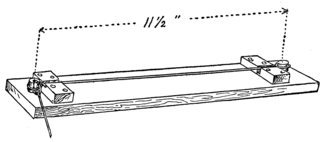
Fig. 78. Forming the Links.
form consisted of a 1-inch board in which two 1/2 inch holes
were drilled, just 11-1/2 inches apart, measured from their
centers. An oak pin, 1/2 inch in diameter, was driven into
each hole and projected about an inch above the board. Two
blocks of oak were secured to the baseboard, just before each
pin, as shown in Fig. 78. This form gave great satisfaction.
A groove was cut in the side of one of the pins to receive the
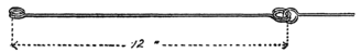
Fig. 79. A Double-Ringed Link.
78
ring of a completed link, while the wire was passed through
this ring and bent around the peg to form the ring of the
new link. After each link was formed it was carefully measured,
and, if too long, was shortened by flattening the rings
endwise, or, if too short, was lengthened by pinching together
the sides of the rings. There were fifty links in our
chain, and every tenth one was formed with a double ring
at the end, so as to distinguish it from the rest (see Fig. 79).
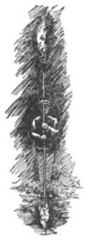
The Surveyor’s Rod.
We completed our outfit by making
a surveyor’s rod out of a straight
stick of wood about 6 feet long. A
target or sighting disk was mounted
on the stick. This disk was 6 inches
in diameter, and was sawed out of a
6-inch square board by making
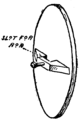
Fig. 81. The Sighting Disk
straight cuts across the corners and then smoothing off the
edge to a perfect circle with a draw-knife. The thickness of
the disk was only 1/2 inch. At the back of the disk we fastened
a block of wood with a slot cut in it to receive the rod,
as shown in Fig. 81. To hold the disk at different heights
79
on the rod a small bolt was used. The nut on this bolt was
slipped into a hole on the block at the bottom of the slot and
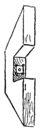
Fig. 82 Nut Fastened in Block.
held in place by driving in nails about it, as illustrated in
Fig. 82. The bolt was then passed through
the hole and threaded through the nut, with
its inner end bearing against the rod. The
disk could thus be held at any desired position
by tightening up the bolt. A piece of
white paper was now pasted over the disk.
The paper was marked off into quarters,
and opposite quarters were
painted black so that it would
be easy to sight, from a distance, the exact center
of the target.
A Simple Method of Surveying.
Of course, none of us had studied trigonometry, but Uncle Ed devised a very simple method by which we could determine distances quite accurately without much figuring.
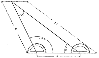
“If you will tell me the length of one side of a triangle and the angles it makes with the other two sides,” said Uncle Ed, “I’ll tell you the length of the other two sides and the size of the third angle. This is how I will do it:
“Say the line is 6 inches long and one angle is 35 degrees, while the other is 117 degrees. Let us draw a 6-inch straight line. This we will call our base line. Now we will place the 80 base edge of our protractor on the base line with its center at the right hand end of the line. At the 37 degree mark we will make a dot on the paper so, and draw a line from the right hand end of the base line through this dot. Now we will do the same thing at the opposite end, making a dot at 107 degrees from the line, and draw a line from the left hand end of the base line through this dot.
“If we extend these lines until they intersect, we will have the required triangle, and can measure the two sides, which will be found to be about 12 inches and 8 inches long, and the third angle will measure just 26 degrees. It doesn’t make any difference on what scale we draw the triangle, whether it be miles, yards, feet, inches or fractions of an inch, the proportions will be the same. If the base line had been 6 half-inches, or 3 inches long, and the same angles were used, the other two lines would measure 12 half-inches, or six inches, and 8 half-inches, or 4 inches. If the base line were 6 quarter-inches long, the sides would be 3 inches and 2 inches long.
81“Now, for example, I am going to measure the distance
to that tree over there. Get out your chain and measure off
a straight line 10 feet long. Now, I’ll set the surveying
instrument with the plumb-bob right over the end of this
line, and sight through the two sight holes until I bring the
two vertical hairs in line with each other and the tree. Look
at the compass needle. It points to the 173 degree mark on
the cardboard ring. Now, Bill, you hold the rod at the other
end of our base line while I swing this instrument around
and sight it. There, the needle points to 92 degrees, and
subtracting this from 173 the difference, 81 degrees, is the
angle at the right end of our base line. We’ll do the same
thing at the other end of our line. See, the compass needle
points to 189 degrees, and now sighting to the pole at the
other end of the line we find that the needle points to 268.
The difference, 79 degrees, is therefore the size of the angle
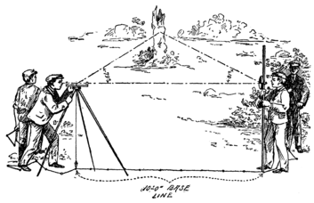
Fig. 84. Determining the Distance to the Tree.
at the left end of our base line. Now we will draw this out
on paper, as we did our first triangle, using quarter-inches to
represent feet. Our base line was 10 feet long, and we will
therefore draw a line 10 quarter-inches, or 2-1/2 inches long,
on our drawing board. On this line we will construct the
triangle, using the angles 81 and 79 degrees. There, that’s
how our triangle looks, and the right hand side measures
7-1/4 inches, while the left hand side measures 7-5/16 inches.
That is, 29 quarter-inches for one side and 29-1/4 quarter-inches
for the other. As each quarter-inch represents a foot,
you will find that the tree is about 29 feet from the right
end of our base line and 29 feet 3 inches from the left hand
82
end. Of course, our instrument is not perfect, neither is our
drawing; but if you measure it off with the chain you will
see that I am not very far from correct.”
Mapping the Island.
Most of our surveying was done by actual measurement, the surveying instrument being used only to determine the exact direction of the measurement. However, there were some measurements which we could not make directly with the chain. For example, we wished to know just how far it was from our tent to the Jersey shore of the river. We measured off a base line along our shore 400 feet long and sighted to a point directly across the river from our tent. The angle in front of our tent was 90 degrees, and at the 83 other end of the base line was 73 degrees. When we drew out our triangle on the scale of 100 feet to the inch we found that the shorter side directly in front of the tent was almost exactly 13 inches long. This meant that the river at this point was 1,300 feet wide, nearly a quarter of a mile. On the other side of the island we found, in the same way, that the river at its narrowest point was about 500 feet wide. This portion of the river we named Lake Placid, as the water was very still and quite deep. This was due to a sort of natural dam formed at the lower end of our island. The small island that Dutchy found was kite-shaped, with a tail of boulders which extended almost all the way across to a rocky point on the Pennsylvania shore. The channel between “Kite Island,” as we called it, and Willow Clump Island was not more than fifteen feet wide in some places, and through this the water swept with a swift current down past a narrow neck of land to join the main current. This narrow stretch of land we named the Tiger’s Tail, owing to its peculiar shape. It was in the hook at the end of this tail that we discovered the old bridge wreck above referred to. From the tip of the Tiger’s Tail to Point Lookout, at the extreme upper end of Willow Clump Island, it was a little under a half-mile. The shore all along Lake Placid was very steep, except near Point Lookout. At one place there was a shallow bay which we called the lagoon.
Lake Placid was a favorite swimming place for us. We used to plunge in from the branches of a tree which overhung the water a little ways above the lagoon and made a natural springboard. We could all swim like ducks, except Dutchy, who couldn’t do anything but paddle. However, Uncle Ed was an expert, and he took Dutchy in hand and soon made a pretty good swimmer out of him. He also taught us some fancy strokes. Of course I took no record 85 of these lessons. You would hardly expect me to sit on the bank with a book in hand jotting down notes while the rest were splashing around in the cool water having the best of fun in the world, and even if I had, I wouldn’t republish the notes here, because whoever heard of a boy learning to swim while reading a book on the subject? A beginner had better leave books alone and plunge right into the water. He will soon learn to keep himself afloat and can then practise any fancy strokes that he sees others try. Then, again, don’t try to learn in shallow water, because you will never do it. Of course it doesn’t pay to jump into water that is over your head unless there is a good swimmer near by to help you out. But you will never learn to swim until you have become accustomed to putting your head under water. You can not swim with a dry face. The first time we went swimming, we couldn’t persuade Dutchy to try it. The water was deep right up to the very bank and he had never been in over his head. Instead he sat up in the diving tree swinging his feet and trying to hide the fact that he was having a dull time.
“Say, we’ve got to douse that fellow,” said Reddy.
“You’re right; he needs a wash,” said Jim. “Let’s sneak up behind him and chuck him in.”
They landed a little ways up the stream behind a large bush and then crept down stealthily on their victim. But Dutchy had his suspicions aroused and saw them coming. He scrambled out of the tree in a jiffy and tore off into the woods as fast as his legs could carry him.
Swimming on a Plank.
86We didn’t expect to see him again that afternoon, for the pace he was leading should have carried him miles in no time; but while he couldn’t swim, Dutchy had his own ideas of fun on the water. It was about twenty minutes later that we saw him coming down-stream lying full length on one of the 2-inch planks taken from the bridge wreck. He was paddling himself along with arms and legs hung over the sides of the plank. We all gave him a cheer, and then started out to have some fun with him. We tried to pull him off his raft, but he stuck on like a leech. It was only when we made his craft turn turtle that Dutchy got his head under water. But it wasn’t a moment before he scrambled back on top again, gasping and sputtering to get the water out of his nose and mouth.
Uncle Ed all this time had been sunning himself on the 87 bank, when suddenly he uttered a shout of warning. We were right at the mouth of the mill-race. For the moment we forgot about Dutchy, and swam out for shore. Before we realized it Dutchy was caught in the current, and was being swept full tilt down the stream. My but wasn’t he scared. I can see him yet clinging for dear life to the plank, his face the color of ashes and his eyes bulging out in terror. First he tried to make for the bank, but the water was so swift that when the front end of the board struck land the rear end swung around in a circle, carrying him on again, but backward this time, before we could reach him. Two or three more times the plank struck the bank and turned him around, while we raced along the high bank, scrambling down to catch him every time he headed for shore, but each time just missing him. Then he swung out past the Tiger’s Tail into the open river just above the rapids. Fortunately he was going along headforemost this time, and Uncle Ed, who had just arrived, panting and breathless, from running, shouted to him to keep his head and steer for a narrow opening between two jutting boulders. I don’t know whether Dutchy did any steering or not, but the raft shot straight through the opening, and was lost in a cloud of spray. In a moment he reappeared below the rapids, paddling like mad for a neck of land on the Pennsylvania side of the river.
Dutchy would never own up that he was afraid. He never told a lie under other circumstances, but when it came to a question of courage he had the habit of stretching facts 88 to the very limit. Even in this case, he said that he started out with the idea of shooting the rapids, and if we hadn’t flustered him so, he would not have bumped into the bank and turned about so many times. Dutchy was a very glib talker. He nearly persuaded us that it was all done intentionally, and his thrilling account of the wild dash between the rocks and through the shower of spray stirred us up so that we all had to try the trick too.
Shooting the Rapids.
The next day, while Uncle Ed was taking a nap, we stole off to the upper end of Lake Placid, each one towing a plank. We needn’t have been so afraid of Uncle Ed, for we found out later that he intended to try a plank ride through the rapids himself next time he went in swimming. Down Lake Placid we paddled in single column to the mill-race. In a moment the current had caught us and we were off. I shall never forget the thrilling ride down the swirling mill-race, the sudden pause as we shot out into the open river, the plunge between the boulders and the dive through the spray. It was all over too soon. Something like coasting–whiz, whiz-z-z, and a half-mile walk. Were it not for the trouble of hauling the planks back by the roundabout course along the Pennsy shore we would have thought shooting the rapids a capital game.
Restoring the Drowned.
89It was on the second day after Dutchy’s exploit of the
rapids that Bill came so near drowning. He probably
would have drowned if Uncle Ed hadn’t been on hand to
work over him. Bill was a fine swimmer, but even the best
of swimmers will sometimes get a cramp, so it is never safe
for any one to go into the water without some one at hand
to help him out in case of accident. In the present case Bill
was doing some fancy strokes by himself over near the
Pennsy shore, while the rest of us were watching Uncle Ed
give Dutchy a lesson in swimming. All of a sudden Bill
threw up his hands and sank. I happened to glance up as
he did it. We thought he was fooling at first, but soon made
out that he was in genuine trouble. Uncle Ed dropped
Dutchy to my tender care, and raced over with a powerful
stroke to the spot where he had last seen his nephew. He
failed to find him on the first dive, but the second time was
successful and he carried the lifeless body to the Pennsylvania
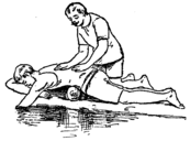
Fig. 87. Pressing the Water out of the Stomach.
shore. In the meantime I had
landed Dutchy and with the rest
of the boys had crossed the lake.
Uncle Ed first laid Bill on
his back and hastily wiped
dry the mouth and nostrils.
Then he pried his jaws
apart, holding them open
90
with a piece of wood wedged in between the teeth. After
which he turned him on his face over a log which was placed
under his stomach. By stomach I do not mean the bowels,
but the real stomach, which lies just under the ribs in front.
Then he pressed with a good weight on the back directly
over the log for nearly a minute, causing the water to flow
out of the mouth. Dutchy had by this time rowed across in
the scow, in which fortunately there happened to be some of
Uncle Ed’s clothing. This he took and rolled into a bundle,
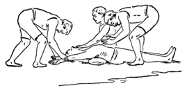
Fig. 88. Expanding the Chest.
then Bill was laid on his back over the roll of clothing,
which was arranged to raise the pit of his stomach above the
rest of his body. Uncle Ed now wrapped a handkerchief
around his forefinger, and with it wiped out Bill’s mouth
and throat. Reddy, who was the least excited of the lot,
was told to draw Bill’s tongue forward so as to prevent it
from falling back and choking the windpipe. This he did
with the dry part of the handkerchief, drawing the end of the
tongue out at the corner of the mouth, and holding it there
while Uncle Ed and I started the pumping action, which
91
produced artificial respiration. I was directed to grasp Bill’s
arms just below the elbows, and swing them vertically in
an arc until the hands met the ground again above the head.
This expanded the chest. Uncle Ed at the same time stood
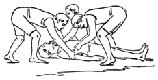
Fig. 89. Squeezing out the Air from the Lungs.
over the body with his elbows on his knees and hands extended,
as illustrated in Fig. 88. Then I swung the arms
up and back to the sides of the body, but just before the
hands touched the ground Uncle Ed seized the body in both
hands just below the ribs, and as soon as I touched the arms
to the ground he
swung forward with
all his weight on his
hands, squeezing
the waist
and pushing
upward so as
to force out
the air in the chest. Then he slowly counted, one, two,
three, four, all the time steadily increasing the pressure,
until at the signal four, with a final push, he shoved himself
to the first position, shown in Fig. 88. At the same
signal I drew the arms up again over the head, and held
them there while Uncle Ed again counted four; then I returned
the arms to the sides, and Uncle Ed repeated the
squeezing process. These movements were continued for
about three minutes, and then Bill gave a short, faint gasp.
We kept on with the artificial respiration, assisting the gasps,
which gradually grew stronger, until they had deepened into
92
steady breathing. Then we stripped off the wet bathing suit,
and wrapping Bill in Uncle Ed’s clothing, laid him in the
bottom of the boat. While Dutchy hurried the boat across,
Uncle Ed rubbed the patient’s arms and legs. The rest of
us swam over and ran for blankets from the tent. Bill was
wrapped in one of the blankets and the other was used as a
stretcher, on which we carried him to the tent. Then one of
us was sent post-haste across to Lumberville for some
whiskey, which was diluted in hot water and given the patient
a teaspoonful at a dose, every fifteen minutes at first, and then
at less frequent intervals. Uncle Ed kept Bill in bed all
the next day for fear of congestion of the lungs. He told
us that unless the patient kept perfectly quiet for a couple
of days, he was liable to be seized with a sudden attack of
hard breathing that might choke him to death in a short
time. To stop such an attack he told us that the best plan
was to apply a mustard plaster to the chest, and if the patient
commenced to gasp, to start pumping the arms and squeezing
the waist so as to help him breathe. After Bill had come
around and was himself again Uncle Ed gave us a thorough
drill in methods of restoring the drowned. He laid down on
the grass and made us practise on him the various directions
which he gave us.
How to Work Over a Patient Alone.
“If you boys hadn’t been so excited,” he said, “I would
have made you rub Bill’s body and limbs while we were
pumping the air into him, but I knew you would get in the
93
way, and be more of a bother than a help. You must learn
to be calm in any accident; excitement doesn’t pay. Keep
steadily and slowly at your pumping, for you might have to
do it for four hours before the patient comes to.” He taught
us just how to swing the arms and squeeze the ribs to best advantage,
and how to hold the tongue without getting in the
way of the arms as they were pumped back and forth. There
was also a special way of rubbing the arms and legs. The
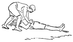
Fig. 90. Working alone over a Patient.
limbs were always rubbed upward,
or toward the body, with the bare
hands, or a dry cloth if there was
one at hand,
but this all had
to be done
without interfering
with the
pumping action.
“If the patient doesn’t come around in five minutes,”
he said, “turn him on his face again over the roll of clothing,
or any other suitable substitute, and press out the water from
the stomach, rolling him first to one side and then to the
other; be sure to get all the water out.” When we had
learned our lesson well, Uncle Ed took Dutchy for his
patient, and proceeded to show us how a man could work
over him alone. First he went through the operation of
squeezing the water out of him, and drying his nose and
mouth, much to the patient’s discomfort; then he drew
Dutchy’s tongue out of the corner of his mouth, holding it
94
there by closing the jaws on it, and holding the jaws together
by passing a handkerchief over his chin and lapping it over
his head. After that he began to pump, seizing the patient’s
arms and swinging them up over the head and back, as before.
Just as the arms were dropped back to the sides of
the body, he squeezed them in against the ribs, at the same
time drawing upward toward the head and counting four
each time, as he had done before. But the lesson was
abruptly interrupted by Dutchy, whose imagination was
worked up to such a pitch that I actually believe he thought
he had been drowning. Anyway, he squirmed out of Uncle
Ed’s grasp, and wouldn’t play patient any longer. For
several days after that we couldn’t persuade him to venture
near deep water.
Willow Clump Island was, for the most part, a trackless wilderness, and as soon as we had made our map we laid out roads to the different important points. Our main highway ran from Point Lookout to Tiger’s Tail. This road was made rather winding, to add to its picturesqueness, and from it a number of shorter roads branched off.
Spar Bridge.
We 96 ran a bridge across the mill-race at its narrowest point. This bridge was made of trees which we had cut down in making our road. It was quite a piece of engineering, built under Uncle Ed’s guidance. Two frames were made of the shape shown in Figs. 91 and 92. The side sticks were 15 feet long and spaced about 10 feet apart at the base by crosspieces. At the upper end one frame was made 6 feet wide and the other 5 feet wide. The side and cross spars were mortised together and secured by lashing a rope around them. To make the frames more rigid we braced them with diagonal braces nailed on. When completed we set the frames up on opposite sides of the stream and with ropes 97 carefully lowered their upper ends until they interlocked, the side spars of each frame resting on the cross spars of the other. In the angles formed by the crossing side spars a center spar was laid, and a number of floor beams or spars were stretched to this from the opposite shores. On these a flooring was spread made of saplings, cut and trimmed to the right size. A rustic railing on each side of the bridge completed the structure.
The Rope Railway.
98The mill-race was crossed further
down by a rope line on which we rigged
a traveling carriage. A light manila
rope was used, anchored to a tree
at each side about fifteen feet from
the ground. A pulley block
with a wheel or sheave 4 inches
in diameter was mounted to
travel on the rope. Suspended
from this block by means of fall
and tackle was a swing seat. This,
as shown in Fig. 94, was merely a
Fig. 95. Tying the Ropes to the Seat.
board fastened with four rope strands
to the ring of the tackle block. A
single rope was used, with the ends
tied firmly together. The loop thus
formed was passed through the ring
99
of the tackle block and the opposite ends were twisted over
the ends of the seat board in the manner illustrated in Fig.
95. The tackle blocks were quite small, having 2-inch
sheaves, and they, together with the large pulley or “traveling
block,” as we called it, cost us about $2.50. Two light
ropes were fastened to the large traveling block, each rope
long enough to reach across the stream. The ropes extended
to opposite anchorages, where each was passed over
a branch of the tree and belayed on a cleat within easy reach.
A fellow could draw himself up clear of the ground by pulling
on the free end of the fall, as a painter does; then tying
the swing fast in this position, he would pull himself across
the stream by means of the rope stretched to the opposite
anchorage. The swing could be drawn back by the next
one who wanted to cross. We also used this aerial line for
transporting loads from one island to the other.
Suspension Bridge.
Our aerial railway didn’t last
long. We soon tired of it, and
instead utilized the materials for
a rope suspension bridge. We procured from Lumberville
half a dozen old barrels and used the staves as a flooring for
the bridge. The staves were linked together by a pair of
ropes at each end woven over and under, as indicated in the
drawing Fig. 97. Notches were cut in the staves to hold
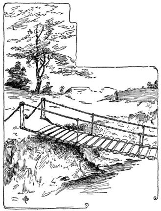
Fig. 98. The Suspension Bridge.
the ropes from slipping off. The flexible flooring thus constructed
100
was stretched across the river and secured to stakes
driven firmly in the ground. A pair of parallel ropes were
extended across the stream about three feet above the flooring,
with which they were connected at intervals of five feet.
The bridge was 25 feet long,
and while rather shaky, owing
to the fact that there were
no braces to prevent it from
swaying sidewise, still it
was very strong and did excellent
service.
Pontoon Bridge.
101At the head of the mill-race, where the channel was fifty
feet wide, we built a pontoon bridge. We were fortunate
in securing six good cider barrels at low cost, also a quantity
of “slabs” from one of the sawmills of Lumberville.
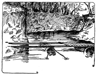
Fig. 99. The Pontoon Bridge.
“Slab” is the lumberman’s name for the outside piece of a
log which is sawn off in squaring up the sides. We made a
raft of these materials and floated them down the river to
Lake Placid. The bridge was made by anchoring the barrels
in the channel about eight feet apart, and laying on them the
floor beams, which supported a flooring of slabs. The floor
beams were narrow planks 1 inch by 4 inches, taken from
102
the bridge wreck, and they were placed on edge to prevent
sagging. Of course we had no anchors for securing the
barrels, but used instead large stones weighing about 100
pounds each, around which the anchor lines were fastened.
We found it rather difficult to sink these improvised anchors
at just the right places, for we were working at the very
mouth of the mill-race, and were in constant danger of having
our scow sucked down into the swirling channel. Once we
were actually drawn into the mill-race and tore madly down
the rushing stream. By Bill’s careful steering we managed
to avoid striking the shore, and just as we were off the
Tiger’s Tail Reddy succeeded in swinging a rope around an
overhanging limb and bringing us to a sudden stop. A
moment later we might have been dashed against the rocks
in the rapids below and our boat smashed. Shooting rapids
in a scow is a very different matter from riding through them
on a plank.
The King Rod Truss.
Our bridge building operations were not entirely confined to the island. Two of them were built on the Schreiner grounds at Lamington. Reddy Schreiner’s home was situated a little distance above the town where Cedar Brook came tumbling down a gorge in the hills and spread out into the Schreiners’ ice pond. Thence it pursued its course very quietly through the low and somewhat swampy ground in the Schreiners’ back yard. Over this brook Reddy was very 103 anxious to build a bridge. Accordingly, before returning to school in the fall Bill made out a careful set of plans for the structure, and after we had gone the rest of the society, under Reddy’s guidance, erected the bridge.
The structure was a cross between a suspension bridge and
a spar bridge. The banks of the stream were so low that,
instead of resting the floor of the bridge on top of the inclined
frames, as we had done over the mill-race, it was
suspended from the spars by means of wires. The crossing
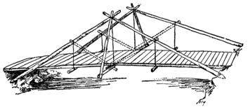
Fig. 100. The King Rod Bridge.
ends of the spars were nailed together and their lower ends
were firmly planted about four feet apart in the banks of the
brook. A stick nailed to the apex of each pair of spars
served temporarily to brace them apart. The center cross
beam of the bridge was now suspended from the spars by
means of heavy galvanized iron wire (No. 14, I should say).
The beam was hung high enough to allow for stretch of the
wire, making the roadway incline upward from both sides
to the center. Aside from carrying the floor of the bridge,
104
this beam was used to brace the inclined spars when the
temporary crosspiece was removed. The ends of the beam
projected about thirty inches beyond the bridge at each
side, and they supported braces which extended diagonally
upward to the crossing ends of the spars. When this was
done the temporary crosspiece above referred to was removed.
As the span between the center cross beam and the
banks was a little too long to provide a steady floor, a couple
of intermediate cross beams were suspended from the inclined
spars. The floor beams were then laid in place and
covered with a flooring of slabs.
Stiffening the Bridge.
The bridge was a pretty good one, except for a slight unsteadiness between the center and either end. When Uncle Ed saw it he showed us at once where the trouble lay. Our intermediate cross beams were hung from the center of the spars, and consequently made them bend, because the strain came across their length, while at the center of the bridge there was no chance for the spars to bend, because the strain was exerted along their length, that is, it tended merely to push the ends of the spars deeper into the banks. To remedy the trouble he proposed propping up the center of each spar with a brace running from the center crosspiece. The dotted lines in Fig. 100 show how these braces were applied. They made the floor perfectly solid throughout, and gave the bridge a much better appearance. Uncle Ed told us that the 105 structure might be called a “king rod truss,” except that in place of rods we had used wires.
The King Post Bridge.
The other bridge on the Schreiner property was built in the following summer, just before we started on our second expedition to Willow Clump Island. It spanned the brook at the gorge, and was therefore a more difficult engineering feat. Mr. Schreiner himself asked us to build it, and we felt greatly honored by the request. A search was made in the Van Syckel library for a suitable type. At last we found one that seemed properly suited to the requirements. It was called a “king post truss,” and was very similar to the king rod bridge. While the design of the bridge was simple, yet it required some ingenuity to put it together. In setting up the other bridge the scow had been anchored in the center of the stream and used as a working platform, from which it had been an easy matter to put the various parts together. In this case our scow was obviously of no use, so we laid a couple of long logs across the chasm, and a few slats were nailed across them to provide a temporary bridge or working platform. The platform sagged considerably at the center, because the span was fully eighteen feet; but the logs were large, and we knew they were strong enough to support our weight. However, as an extra precaution, we tied the ends to stakes driven in the ground, so that they could not possibly slip off the banks.
106First we set about constructing the king posts, which were
made as shown in Fig. 101. Two stout posts 7 feet long
were connected at the top by a tie stick, which spaced them
4 feet apart. To make a secure fastening they were notched
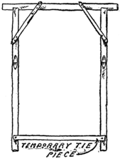
Fig. 101. The King Post Frame.
together and strengthened with diagonal braces. Each king
post was notched on opposite sides, at about thirty inches
from the top. A temporary
tie piece was also nailed
across the lower ends of the
king posts. The frame
thus formed was set up at
the center of the span and
temporarily held by nailing
the lower tie piece to the
working platform. Four
stout spars were now cut,
each about fifteen feet long.
Taking a pair at a time, we
planted their lower ends
firmly in the opposite banks
and sawed off their upper
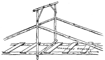
Fig. 102. The King Posts Set in Position.
ends until they could just be hammered into the notches in
the king post. This required careful fitting, but by making
the spars a little too long to start with, and then shaving
them down with a draw-knife, we managed to make fairly
good joints. A couple of long wire nails in each spar made
the structure perfectly secure. The king posts were now
sawed off just above the temporary tie piece, and the
107
permanent cross beam was fastened to these ends with straps
of heavy wire wound tightly about them. The working platform
sagged so much that we were able to lay this cross
beam above it. From the ends of the cross beam diagonal
108
braces extended to the king posts (Fig. 103). Our working
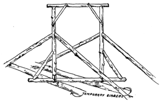
Fig. 103. The Permanent Cross Beam Made Fast.
platform was now removed and replaced with the permanent
floor beams, which were firmly nailed to the center cross
beam and to the inclined spars at the shore ends. The floor
beams were quite heavy and needed no support between the
king posts and shore. A rustic floor was made of small logs
sawed in two at Mr. Schreiner’s sawmill. Light poles were
nailed to the flooring along each edge, giving a finish to the
bridge. We also provided a rustic railing for the bridge of
light poles nailed to the king posts and the diagonal spars.
Like all inhabitants of islands, we early turned our attention to navigation. Our scow was serviceable for transporting materials back and forth across the strips of shallow water between our quarters and the Jersey shore. We never attempted to row across, because progress would have been entirely too slow, and we would have drifted down to the rapids long ere we could reach the opposite side. But on Lake Placid matters were different. Although there was no settlement near us on the Pennsylvania shore, to occasion our crossing the water for provisions and the like, yet the quiet stretch was admirably suited to boating for pleasure, and mighty little pleasure could we get out of our heavy scow.
Uncle Ed’s Departure.
Owing to a sudden business call Uncle Ed left us after he had been with us nearly three weeks. But, before going, he explained carefully to Bill just how to construct a canvas canoe. Jack, the cook, who was anxious to lay in a second supply of provisions, accompanied Uncle Ed as far as Millville, the next town below Lamington. Here Uncle Ed 110 bought five yards of canvas, 42 inches wide, several cans of paint and a quantity of brass and copper nails and tacks. These supplies, together with the food provisions that Jack had collected, were brought to us late in the afternoon by Mr. Schreiner. Mr. Schreiner also brought the necessary boards and strips of wood for the framework of our canoe.
A Visit from Mr. Schreiner.
We invited Mr. Schreiner to spend the night with us, and this he did after fording with some difficulty the swift-running river. In the morning we showed him our quarters, our filter, the roads we had built, the spar bridge across to Kite Island, our surveying instrument and the chart we had made of the vicinity. He was greatly pleased with our work, and it was then that he gave us an order for the bridge over the gorge. From that day on he became our staunchest ally, so that when my father and Mr. Van Syckel complained that we were loafing away a lot of time which could be more profitably spent in study or work, Mr. Schreiner stood up for us and declared that our experiences on the island were doing us far more good, both physically and mentally, than any other work that they could conceive of; that before condemning us they should pay us a visit and see how we were employing our time.
The Sailing Canoe.
111Immediately after Mr. Schreiner’s departure we started
work on the canoe. A strip of spruce 1 inch thick, 3 inches
wide and 12 feet long served as the keelson. At the stern a
post 1-1/2 inches thick, 3 inches wide and 13 inches high was
secured to the keelson
with brass
screws. This was
braced as indicated
in Fig. 104. At the
bow a stem piece
was attached to the
keelson. This stem was cut to a somewhat semicircular form,
as shown in Fig. 105. The outer edge was tapered with a
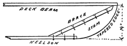
Fig. 105. Stern of the Canoe.
draw-knife to a thickness of 1/4 inch and a brace was nailed
to the inner edge. Our next work was to cut out three
forms, one of the shape shown in Fig. 106 and two like
that shown in Fig. 107. The first form was set up on the
112
keelson midway between the stem and stern, and the other
two were spaced about four feet each side of the center
form. The center form was used only for shaping the
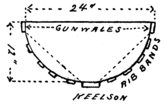
Fig. 106. Center Form.
frame of the boat, and was not intended to be permanently
affixed to the canoe. Therefore, we fastened it to the keelson
very lightly, so that it could be readily removed. The other
two forms, however, were made permanent parts of the
frame, serving as bulkheads. The gunwales were now secured
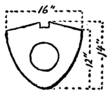
Fig. 107. Bulkheads.
in position. These were of spruce 3/4 inch thick and 2
inches wide. The ends were beveled off so as to neatly fit the
stem piece and the stern post, to which they were fastened
by brass screws. Then we applied the longitudinal strips, or
rib bands, which were of 1/4-inch thick spruce 1 inch wide.
Ten of these bands were used, equally spaced apart on the
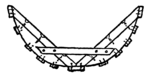
Fig. 108. Center Braces.
center form, to which they were lightly tacked; but they were
nailed securely to the bulkheads and the stem piece and stern
post. The cross ribs were made of barrel hoops which we
had soaked in water for a day or so to render them pliable
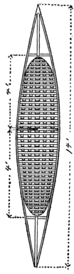
Fig. 109. Top View
of the Canoe Frame.
enough to be bent into place. These hoops were split to a
113
width of 1/2 inch, and secured
first to the keelson, then to the
longitudinal strips and finally to
the gunwales. Copper tacks
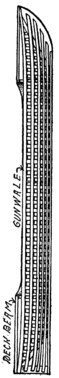
Fig. 110. Side View
of the Canoe Frame.
were used for nailing the ribs in
place, and these were long enough to be passed through the
rib bands and clinched on the outside. Forty cross ribs were
nailed on, and at the
center of the canoe
they were spaced about
three inches apart. The
center form was then
removed and cut along
the dotted lines shown
in Fig. 106. The
semicircular pieces
thus obtained were
now strengthened with
strips on their inner
edges, and wedged in
between the keelson
and the gunwales, to
which they were
nailed, as shown in
Fig. 108. A pair of
cleats nailed to the
cross ribs served as
supports for the seat
114
of the canoe. The frame of the boat was completed by
nailing in place two deck beams of 1/2-inch square pine and
four corner pieces between the gunwales and the bulkheads,
so as to make an elliptical well hole or deck opening. Before
laying on the canvas covering the edges of the gunwales,
keelson, deck beams, stem and stern posts were smoothed
down with sandpaper.
Stretching on the Canvas.
The frame was laid in the center of the canvas and the
latter drawn around it. Then with a large needle and strong
twine we sewed both edges of the cloth together with long
stitches, lacing the canvas over the frame as a shoe is laced
over a foot. This done, the boat was turned deck downward
and the canvas was tacked to the keelson. In each case,
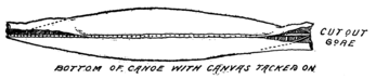
Fig. 112. Tacking the Canvas to the Keel.
115
before driving in a tack a daub of white lead was applied, to
water-proof the spot. At the stem and stern a gore (narrow
triangular piece) was cut out of the canvas so as to make it
lie smooth on the frame, and white lead was painted in between
the overlapping edges. The canoe was then turned
deck upward and the lacing tightened, while we carefully
worked out all wrinkles in the cloth. After tacking the
canvas along the gunwales on the outside, it was trimmed off,
leaving sufficient margin to be brought over the gunwales
and tacked inside. Two triangular pieces were cut out for
the decks, and these were lapped over the outer canvas and
tacked to the gunwales. A narrow molding along the edge
of the boat served to cover the tack heads and added a certain
finish to the canoe. A keel plate 2 inches wide and 1
inch thick was attached to the outside of the boat, and then,
after wetting the canvas, it was given a coat of white lead
and oil. When this was perfectly dry it was sandpapered
and the second coat applied.
The Rudder.
The canoe was now complete
except for the rudder,
which was cut from a 1/2-inch
board to about the shape
shown in Fig. 114. Strips 1-1/2 inches wide and
1/2 inch thick were nailed to each side of the
blade, forming a post, to the top of which a
116
crosspiece or tiller was fastened. A cleat nailed to the pillar
at each side of the rudder post served to greatly strengthen
the joint. The rudder was hinged to the canoe by a rod,
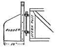
Fig. 114. The Rudder Hinge.
which passed through four brass screw
eyes, two threaded into the rudder and
a corresponding pair screwed into the
stern. For convenience in steering we
ran our tiller rope clear around the
boat, through screw eyes in the gunwales
and a pulley at the stem, so that the steersman could
guide his craft from any point in the canoe.
The Deep Keel.
We planned to use our canoe as a sailboat, and had to provide a deep keel, which, for convenience, was made detachable. This keel was 6 inches wide, 1/2 inch thick and 6 feet long, and was fastened at the center 117 of the canoe. Screw eyes about twelve inches apart were threaded alternately into opposite sides of the keel plate. Corresponding hooks were attached to the keel in position to hook into the screw eyes, and thus hold the keel firmly in place.
Canoe Sails.
Our boat was fitted with two masts, a
mainmast and a mizzen or dandy mast.
The former was 6 feet long and the latter
4 feet long, and each measured 1-1/2
inches in diameter at the base, tapering
to about 1 inch diameter at the
upper end. They were held in brass
bands, or clamps, bent around them
and secured to the bulkheads, as shown
in Fig. 117. The sails were of the
lanteen type.
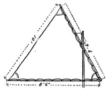
Fig. 118. The Mainsail.
The mainsail measured 8-1/2 feet along
the boom, 9-1/2 feet along the yard
and 10 feet at the leach. The
dimensions of the mizzen sail
were: along the boom, 5 feet;
along the yard, 5-1/2
feet; and at the leach,
6 feet. The boom was
attached to a strap of
leather on the mast,
118
and was thus given freedom to swing around in any desired
position. The yard was similarly attached, and was raised
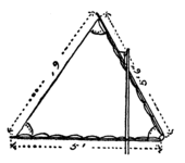
Fig. 119. The Mizzen Sail.
by a cord, which passed through pulleys
at the top and at the base of the mast
and extended to a cleat within easy
reach of the occupant of the
boat. A double paddle was
fashioned from a board 1
inch thick, 6 inches wide
and 6 feet long. The
blades were shaved down to
a thickness of 3/8 of an inch
at the edges.
It will be observed that we used no iron in the construction of this boat. Uncle Ed has warned us not to, because iron rusts out so easily and is apt to damage both the canvas and the wood with which it is in contact.
A canoe is rather a tipsy thing to sail in, as we soon learned,
and it was lucky that we could all swim, else our vacation
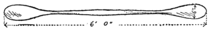
Fig. 120. The Double Paddle.
might have ended very tragically; for the very first time Bill
and I tried the boat an unexpected gust of wind struck us
and over we went. We were very poor sailors at first, but
it didn’t take us long to catch on.
Lee Boards.
119One thing that bothered us greatly in sailing was the keel of our canoe. It was forever getting twisted, particularly when we tried to make a landing. There were only a few places along the island where the water was deep enough to permit our coming right up to shore without striking the keel. The fastening was not very strong, and every once and awhile it would be wrenched loose. The matter was made the subject of a special letter to Uncle Ed, and in due time his answer was received. As usual, he offered a first-class solution of the difficulty. “Don’t use a keel,” he wrote; “lee boards are much better.” Then he went on to explain what was meant by lee boards: “The leeward side of a boat is the opposite of the windward side; that is, that side of the boat which is sheltered from the wind. Lee boards, then, are boards which are hung over the lee side of a boat to prevent it from drifting to leeward, and they serve to take the place of a keel or centerboard.”
Following Uncle Ed’s direction
we fastened a strip of wood across
the canoe about six feet from the
bow, nailing it firmly to the gunwales.
This provided a support to
which the lee boards were secured.
The lee boards were paddle-shaped
120
affairs of the form and dimensions shown in Fig. 121. Each
paddle near the top was hinged to the end of a board three
inches wide and a foot long. The paddle was held at right
angles to the board by means of a
hook. Each board was fastened
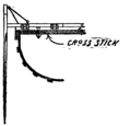
Fig. 122. Section of the Canoe, Showing Lee Board.
with door hinges to a baseboard
which extended the width of the boat
and was attached to the crosspiece
of the canoe by means of a couple of
bolts. The bolt heads were countersunk,
so that the hinged boards could
lie flat over them. To the top of each lee board two ropes
were attached, one passing forward around a pulley and
thence back to a cleat within easy reach of the occupant of
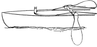
Fig. 123. The Lee Boards in Use on Canoe.
the canoe, and the other passing directly back to this cleat.
By pulling the former rope the lee board was lifted out of
the water, while the latter rope was used to swing the board
into working position. When tacking to port (left), the
board on the left side of the canoe was lowered and the
other was raised, as shown in Fig. 123, and when tacking to
121
the starboard (right) the board on the right side was lowered,
while the left one was raised.
The Indian Paddling Canoe.
Our sailing canoe proved such a good one that we decided
to build a second. This was to be much lighter, for paddling
only, and of the true Indian shape, with wide, bulging
sides and raised stem and stern. The dimension of the
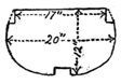
Fig. 125. Intermediate Form.
forms used are given in Figs. 124 and 125. These forms,
it will be observed, were notched to receive the keelson and
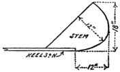
Fig. 126. The Stem Piece.
gunwales. The keelson was formed of 1-inch spruce 3
inches wide and 10 feet long. The stem and stern, which
were both of the same shape, were cut from a
12-inch board to the form shown in Fig. 126,
and were firmly secured to the keelson.
This made the boat 12 feet
long. The forms were then
set in place on the keelson,
one at the center and the
122
others three feet each side. The gunwales were formed
of 3/4-inch by 2-1/2-inch spruce, and the twelve rib bands used
were of the size used in our first boat. As none of these
forms was to remain in the boat, nails were driven very
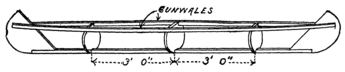
Fig. 127. Skeleton Frame of Canoe.
lightly into them, with heads projecting so that they could
easily be withdrawn when it was time to remove the forms.
The cross ribs were passed under the keelson inside of the
rib bands and outside of the gunwales, as shown in Fig. 128.
After they were set in place and firmly secured with copper
tacks, a band was nailed to the keelson to form the keel.
To produce the raised stem and stern, four
wedge-shaped pieces were nailed to
the tops of the gunwales, as
indicated in Fig. 129. The
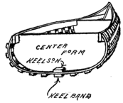
Fig. 128. Section at Center of Canoe.
forms were then removed
and were replaced with
cross sticks braced between
the gunwales. The center
cross stick was provided
with two corner pieces, as
shown in Fig. 130, adapted to fit under the gunwales and
against the rib bands. The canvas was then applied in the
manner described before, but was tacked to the upper edge
123
of the gunwale instead of the outer side, and the tacks were
covered by a half-round molding which extended around the
entire boat. After the lacing was cut the edge of the canvas
was secured to the
under edges of
the gunwales.
The canoe was
then completed
by fastening on a
1-inch square keel
and treating the
boat with two coats of paint. The paddle was a duplicate of
the one described in connection with the sailing canoe.
I remember that we eventually equipped our paddling canoe with a sail and a pair of lee boards, though no record of this fact appears in the chronicles of the society.
One afternoon Fred, who had waded over to Lumberville after some provisions, came splashing back holding aloft a large square envelope. It was from Uncle Ed and contained a photograph of a group of Wichita Indians building a large grass lodge. In a brief explanatory letter Uncle Ed suggested that we build a similar hut on our Island.
The Grass Hut.
The grass lodge appealed
to us as very
picturesque, and we
set to work immediately
on its construction.
We made our
hut much smaller,
however, only 12
feet in diameter,
and 8 or 9 feet
high. First we procured
two dozen
light poles between
10 and 12 feet long.
125
These we set up about 18 inches apart in a circle like a stockade,
the sticks being buried in the ground to a depth of 12
inches. At one side a space of 3 feet was allowed for a
doorway. Inside the stockade we erected a working platform
of planks supported on barrels, and standing on this
we took two opposite poles, bent them inward and lashed
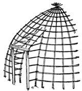
Fig. 132. Doorway of the Hut.
their upper ends together. Then a second
pair of opposite poles were similarly
bent inward and tied, and so we
proceeded until the entire stockade
had been converted into
a dome-shaped cage. Around
these poles we laid lighter
sticks, or bands, tying them
at the points of intersection.
At the doorway two posts
were set firmly in the ground,
projecting upward to a height
of 4 feet. A lintel nailed across the top of the posts completed
the door frame. Sticks were nailed to the lintel and
to the side posts, extending to the main frame of the hut, to
which they were tied. We were now ready to thatch our
hut. Reddy and Dutchy went over to Lumberville for
several bales of straw. We tied the straw in bunches and
applied it to the frame, copying, as best we could, the
process illustrated in the photograph.
But for its location the hut would have proved a very serviceable habitation. In order to have a good, dry dwelling 126 without laying down a board flooring, we had selected for its site the sandy shore at Point Lookout. This part of the island was not sheltered with trees, and the hot sun beat down on our hut so strongly that we found the quarters very uncomfortable indeed. It was this fact that led to the construction of a tree hut–a building that would be perfectly dry and yet shaded and cool. Bill had read of such houses in the Philippines and felt confident that we could build one. We couldn’t decide at first where to locate our hut until Dutchy moved that we build it in the gnarled oak tree overlooking the “Goblins’ Dancing Platform.” Immediately the motion was seconded and unanimously carried.
The Goblins’ Dancing Platform.
Just above the town of Lumberville there was a cliff which rose sheer 200 feet above the level of the river. So perpendicular was the cliff that a stone dropped from the overhanging ledge at the top would fall straight down to the railroad track below without touching a twig in its course. Back of this broad ledge there was a very peculiar formation. A column of stone rose abruptly 40 feet higher and was topped with a large slab about 12 feet in diameter. This was known all over that region as the Goblins’ Dancing Platform. The only possible way of gaining the summit of the column was by climbing a scraggly oak tree which grew on the high ground back of the pillar, crawling out on 127 an overhanging limb, and then dropping down to the platform below. It was in this oak that we decided to build our house. It was a very inaccessible spot, and to reach it we had to make a wide detour around the back of the hill, and through the fields of a cranky farmer, who more than once threatened to fill us with bird shot for trespassing on his property. How were we to carry all our building materials up to this great height? One would think that the difficulties would be enough to discourage us, but not so with the S. S. I. E. E. of W. C. I. Nothing daunted us.
Dutchy Takes a Dare.
Our first task was to try some other approach to the top of the cliff. At one side of the overhanging ledge there was a fissure in the rocks which ran from the base of the pillar to the foot of the cliff. Down this zigzag crevice Dutchy had scrambled, one afternoon, on a dare. We were rather frightened when he started, because it was a very hazardous undertaking, and we watched him anxiously, peering over the edge of the precipice. By bracing his back against one of the walls of the rock, and digging his feet into the niches and chinks of the opposite wall, he safely made his way to a shelf about half-way down, where he paused to rest. From that point on the fissure widened out, and a steep, almost vertical incline, sparsely covered with vegetation, led to the railroad track below. I think he must have become rather frightened at his position, because he hesitated long before 128 he resumed his downward course, and when he finally did make the attempt his foot slipped upon the moss-covered rocks and down he fell, scratching and clawing at every shrub within reach. Believing him to be killed, we rushed down the hill and around to the foot of the cliff. It probably took us about fifteen or twenty minutes, though it seemed ages before we came upon our venturesome comrade coolly trying to pin together a rent of inconvenient location and dimensions in his trousers.
“Say, Dutchy, are you killed?” cried Bill, breathlessly.
“Killed, nothing,” he replied, with scorn. “I suppose you fellows think I had a fall. Well, I didn’t.”
“You didn’t, eh? We saw you slip.”
“Oh, go on. I came down that way on purpose. There was no use in picking my way down like a ’fraid cat, when I could just as well take a smooth and easy toboggan slide on the bushes all the way down.”
Smooth and easy toboggan slide! Well, you should have seen the hillside. The course was well defined by the torn and uprooted shrubs and the pile of branches and vines at Dutchy’s feet. Whether the hare-brained Dutchy really imagined he could glide easily down on the shrubbery, his frantic movements on the way certainly belied his story, and when, the next day, we proposed that he repeat the trick, somehow he didn’t seem to be very enthusiastic on the subject.
A Path Up the Fissure.
129It was up this fissure that we decided to haul materials for our tree hut. Our first task was to build steps and ladders in the steepest parts. We had no tool for cutting out niches in the rock, but wherever natural depressions were formed we wedged in sticks of wood between the side walls to serve as ladder rungs. If no such niches appeared for considerable height, we would stretch a rope ladder to the next fixed rung. In most places the natural formation of the rock was such as to afford sufficient footing.
Rope Ladders.
130The rope ladders were made of two parallel side straps, tightly stretched between the fixed sticks, and then at intervals of fifteen inches we inserted the ends of the ladder rung between the strands of the rope. Below and above each rung the rope was bound with cord. The rungs were notched at the ends to prevent them from slipping out.
After providing a means for
scaling the cliff (we called it the
Jacob’s Ladder), we were still
confronted with the problem how to cart our building materials
to the top. It was a very hard task and you couldn’t
have hired us to do it under any other
circumstances. First, Bill planned out on
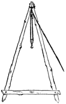
Fig. 136. The Derrick.
paper just how the house was to be
built, and we cut all the pieces to the
right size so as not to carry up
any superfluous matter. When
all was ready the boards and
sticks were loaded on the scow,
and ferried over to the cliff.
Then we carried them on our
backs, three or four at a time,
up the slanting hillside to the
131
first ledge. From there up, owing to the steepness of the
ascent, we had to employ different tactics.
The Derrick.
A derrick was constructed of two sticks 10 feet long, which were bolted together at the top, and secured about five feet apart at the bottom by a cross piece, as shown in Fig. 136. The derrick was then taken apart and with some difficulty hauled piecemeal up to the next ledge above. Here it was put together again. The fall and tackle used in our aerial railway was attached to the apex of the derrick, and the latter was then erected with the legs set into depressions 132 in the ledge and the upper ends slanting outward but kept from falling over the edge by a rope tied to one of the fixed rungs set in the fissure. With this derrick we hoisted up the boards in a few hauls. The job was a very ticklish one, but Bill used the greatest care to prevent accident. The derrick, rope and tackle were carefully tested before used, and as soon as the load was attached to the lower pulley block the two who did the loading were instructed to crawl back into the fissure so as to be out of danger in case anything gave way. At one time a stick which had been carelessly tied did fall, and it might have badly hurt some one had we not observed this precaution. When we had raised the material to the second ledge we transferred operations to the top ledge, and when the materials had been hauled up to this point we finally rigged up our fall and tackle in the old oak tree itself.
The Tree House.
The tree had two large
limbs which extended out at
a wide angle from the main
trunk. Across these two limbs,
at about seven feet out, we laid
our first girder, nailing it securely in place. Then to the
main trunk we nailed the second girder on a level with the
first. Diagonal braces were extended from the trunk to
support the ends of this girder, and a tie piece was nailed to
133
the braces, as shown in Fig. 138, to prevent them from
spreading. The girders were rough sticks about 4 inches in
diameter and 10 feet long. We cut flat faces on them at
the points where they were nailed to the tree, and then, to
make them doubly secured, we nailed cleats, or blocks of
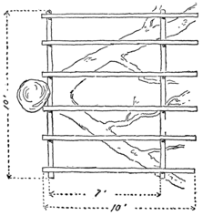
Fig 139. Top View of the Platform.
wood, to the tree under them. The floor beams were then
laid across and nailed to the girders. They were cut to a
length of 10 feet so as to project beyond the outer girder
to provide for a piazza overhanging the Goblins’ Platform.
Six floor beams were used, spaced 20 inches apart. All
branches projecting up between the beams were then cut
away and a flooring of slabs was laid on. To the main
134
trunk six feet above the flooring, a stick or (to use the technical
term), “wall plate,” was nailed on, and its ends were
supported by upright posts resting on the platform. Thirty
inches from the outer end of the platform two more posts
were erected eight feet high and secured by sticks nailed
across from the other posts, and also by a second wall plate
connecting their upper ends. Four more posts were erected,
one between each pair of the corner posts, and then we were
ready to enclose the framing.
The sidewalls were first clapboarded, because we were
afraid the roof would not hold us until the framing had been
135
strengthened by nailing on the siding. Slab boards were
used for this purpose. Beginning at the bottom, the boards
were laid on, each lapping over the one below, as shown in
Fig. 141, so as to shed water. In each side we
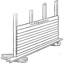
Fig. 141. Nailing on the Clapboards.
cut a window opening and nailed on a
window casing of the type shown
in Fig. 142, which will
be described in a
moment. As soon as the
clapboards were applied,
we nailed on the rafters
and then applied the
roofing. The same principle
was here
used for shedding
water. The
lowest board was
first laid on, and then the others were successively applied,
each lapping over the one below.
The window casings we used
each consisted of a frame about 15
inches square, but with the upper
and lower pieces extending 12
inches beyond one of the side
pieces. On these extended pieces
a slideway was formed for the

Fig. 143. The Window Sash.
window sash by nailing on two strips of wood about 3/4 inch
square and over them a pair of wider strips projecting inward,
136
so as to overlap the edges of the sash. The window
sash consisted of a frame 13-1/2 inches square, made of 3/4-inch
square strips over which canvas was tightly stretched
and tacked. A spool was nailed on at one side for a handle.
These windows were closed only in
rainy weather, to keep the water out.
Sliding Doors.
We had two doors; one at the back of the house, from which a ladder extended down to the ground, and another opening out onto the veranda, from which we dropped a ladder down to the Goblins’ Dancing Platform. In order to save space we used sliding instead of swinging doors. The back door frame was 5-1/2 feet high and the front door frame 6 feet high. The doors were mounted on the outside of the building. The side posts of each frame were 2-1/2 feet apart, and the lintel and sill extended 3 feet beyond the side post at one side. The upper face of the lintel was planed down perfectly smooth, and its edges were tapered off to make a track for the 137 rollers on the door. The rollers consisted of two spools, which turned on tenpenny nails driven into the top of the door. At the lower end two more spools were mounted, turning on nails driven in the bottom edge of the door. The rims of the spools extended slightly beyond the outer face of the door and rolled against the sill. To keep the water from leaking in at the top a slanting board was fastened above it, as shown in Fig. 144. The back door was similarly constructed. Our tree house was completed by a running balustrade around the veranda.
It strangely happened that just after our tree house had been built we received a photograph from Uncle Ed of a Filipino tree house made of bamboo.
We were a proud lot when the house was finally completed. From the veranda we had an excellent view up and down the river. We could see our camp on the island and keep watch of our goods. Late one afternoon Dutchy and I were lolling about on the Goblins’ Platform, idly watching a hawk soaring above us. The rest of the boys had returned to the island in canoes an hour before and left the heavy scow for us to row back. It was drawing near supper time and we had about decided to start for home, when I chanced to see a scow up the river. It looked exactly like ours, and in it were two men, evidently drunk, from the way they carried on. A glance showed me that our scow was not at its moorings. How were we to reach the camp? One of the men had evidently seen us and was pointing us out to his companion. We rushed down the Jacob’s Ladder, but by the time we reached the river bank they were in midstream and heading rapidly northward. Our shouts merely brought forth derisive laughter. We were certainly in a predicament. First we ran back up the cliff, and tried from there to gain the attention of the rest of the fellows. They evidently saw us but couldn’t make out what we wanted. Then 139 we ran down to a point opposite the island and called to them. But the wind was against us and we couldn’t make them hear, so we had to plunge in and wade across.
A Council of War.
Immediately we summoned a war council. Dutchy and Jack were chosen by lot to guard the camp, while the rest of us started in pursuit in canoes. By the time we got under way the sun had dropped back of the Pennsylvania hills and the shadows were climbing slowly up the Jacob’s Ladder. Swiftly we paddled up-stream, keeping close to the western shore, where the water was very quiet. We didn’t expect to go far, because there were rapids less than three miles up, and we were sure that no tramps would ever be ambitious enough to row a heavy scow against the swift current at that point. As we rounded a sharp bend in the river, we noticed a camp fire a few hundred feet further up, around which five or six men were lounging, and there, just below them, was our scow. What were four boys to do against six grown men? We were each armed with a club, and could have made a pretty good fight if necessary, but after a whispered consultation we decided it would be best to wait until dark, when we could creep up quietly and steal away unnoticed with our boat.
Vengeance.
It seemed as if darkness never would come. It was scarcely dusk when our patience gave out and we paddled up 140 stealthily, hugging the shore. Bill gained the scow unnoticed, but just as he was about to push off he discerned the body of a man within. It was one of the tramps lying there in a drunken stupor. What was to be done? Every moment was precious. A yell from the fireside decided him. With a mighty push he launched the boat out into the current, while we threw him a line and towed the boat out to midstream. With a volley of curses the men sprang up and pelted us with stones. But they were poor shots, and we escaped without serious injury. Our prisoner, in the meantime, was snoring heavily in the scow undisturbed. We took him down-stream and then unceremoniously picked him up and dumped him overboard within a few feet of the shore. It was a rude awakening, and nearly frightened the wits out of the man. But it brought him to his senses, and in a moment we were dodging more stones, sent with such good aim that we had to lie flat in the bottoms of the boats until the current carried us out of reach.
A Double Surprise.
It was now quite dark, and we had some difficulty in groping our way back to camp. There was no moon and the stars were obscured by clouds. Our only course was to follow the shore line until we got around the bend, and then we steered for the beacon fire, which, by prearrangement, had been kindled on Point Lookout. But the spirit of mischief was in us. We thought we would have some fun 141 with Dutchy. We could see him silhouetted against the blaze. Jim and I hung back in the canoes, while Reddy and Bill went on with the scow, splashing their oars and shouting and singing in disguised voices, like drunken men. Dutchy was evidently very much agitated. His “Hello, there! Boat ahoy!” was greeted with derisive yells.
“Say, we’ll lick the life out of you, the same as we did them other kids,” shouted Reddy.
This was too much for Dutchy. He ran for all he was worth, yelling for Jack to come quick.
We had a merry laugh over the situation when suddenly the tables were turned. Something whizzed past Bill’s ear; I was stung on the arm with a heavy nail; a 142 large stone hit the scow; Reddy had his hat knocked off, and Fred upset his canoe trying to duck out of reach of the invisible missiles before we could make our assailants understand that we were friends and not the tramps. The joke was on us after all. We hadn’t counted on Dutchy’s accurate aim or Jack’s skill with the crossbow.
Tramp-proof Boat Mooring.
Around the camp fire that night we discussed our adventures and made plans to prevent their recurrence. It was evident, for one thing, that we would have to moor our boats off shore in such a way that they would be out of reach of meddlesome persons, and yet could be drawn in toward shore by any one who knew how. This was the way we did it. A pair of galvanized iron ring bolts were procured on Jack’s next trip to Lamington for provisions, also a light rope about forty feet long. The ring bolts were screwed into a pair of stout anchor stakes about two feet from their lower ends. The rope was passed through the rings and the 143 ends were joined by tying them to a galvanized iron link. Then it was soaked for a while to shrink it before it was set in place. After the rope had shrunk sufficiently, the two stakes were driven into the bed of the river, one close to the bank and the other far enough out to hold the rope belt clear of the bottom. Both stakes were sawed off under water, just above the ring bolts, so that they were hidden from sight. When we wanted to moor our boats we secured their anchor ropes or “painters” to the link. A large stepping stone marked the spot were the inner stake was driven, and standing on this stone we were able to reach down and haul in on the lower strap of the belt to draw the boat out a safe distance from shore, and then when we wanted to use our boat again we would haul in the upper strap to draw the boat in toward shore.
Our tramp adventure was really quite a blessing to us, for it taught us the necessity of a good signaling system between the Goblins’ Platform and the island and led to our learning how to wigwag, and later to the construction of a heliograph. Uncle Ed, when he read of our experience, sent us the U. S. Army “Manual of Signaling.” Fred, the tailor of our camp, made us two white flags with red centers. Each flag was two feet square and was fastened to a light staff about five feet long. Then we got out the manual and practised sending signals, at first within shouting distance, until we got to be quite expert.
Wigwag Signals.
There were only three different movements that could be made with flags, but in the book different combinations of these movements were given to represent each letter of the alphabet and the numbers from 1 to 0. All these movements were begun and ended by holding the flagstaff upright, directly in front of the body, as shown in Fig. 147. The first movement was to swing the flag down to the right and back (Fig. 148), the second to the left and back (Fig. 145 149), and the third forward and back (Fig. 150). The following table gives the different combinations used for various letters:
The Wigwag Alphabet.
| A | 22 | J | 1122 | S | 212 |
| B | 2112 | K | 2121 | T | 2 |
| C | 121 | L | 221 | U | 112 |
| D | 222 | M | 1221 | V | 1222 |
| E | 12 | N | 11 | W | 1121 |
| F | 2221 | O | 21 | X | 2122 |
| G | 2211 | P | 1212 | Y | 111 |
| H | 122 | Q | 1211 | Z | 2222 |
| I | 1 | R | 211 | tion | 1112 |
Numerals.
| 1 | 1111 | 4 | 2221 | 8 | 2111 |
| 2 | 2222 | 5 | 1122 | 7 | 1221 |
| 3 | 1112 | 6 | 2211 | 0 | 2112 |
| 7 | 1222 |
146The numbers 1, 2 and 3 indicate respectively the first, second
and third movements. For instance, A was represented
by the combination 22,
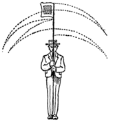
Fig. 151. The Signal for Letter “B.”
which means that the flag
must be swept to the left
and back twice. B is represented
by the combination
2112, that is, a sweep to the
left, two sweeps to the right and a
final sweep to the left, as shown in
Fig. 151. The end of a word was
represented by a sweep forward and
back; the end of a sentence by two
sweeps forward and back, and the end of a message by three
sweeps forward and back. It will be noticed that the same
combinations are used for 2 and Z, 3 and tion, 4 and F, 5 and
J, 6 and G, 7 and V, 9 and M, and 0 and B. The following
abbreviations were given in the Manual:
Abbreviations.
| a | after | n | not | ur | your |
| b | before | r | are | w | word |
| c | can | t | the | wi | with |
| h | have | u | you | y | yes |
These abbreviations saved a lot of time, for when we wanted to signal the word after instead of spelling it out–22-2221-2-12-211-3–we used the signal for A–22–followed 147 by 3 to signify that it was the end of the word. Before was represented by 2112-3, your by 111-211-3, etc. It took quite a little practice to learn the different combinations. Fred and Reddy soon became experts, and could flash the signals back and forth at a great rate.
Wigwagging at Night.
At night we used a torch in place of a flag. The torch consisted of a roll of dried birch bark tied with wire to the end of a staff. It was found necessary to place another torch on the ground directly in front of the signaler so as to fix a central point and enable one to determine whether the moving torch was swung to the left or right. A later improvement was to use three lanterns, one in each hand and one attached to the waist to fix the central position. It was quite an advantage to have a lantern in each hand, for it saved changing over from one to the other when a second movement followed a first or a first movement a second.
The Heliograph.
The book that Uncle Ed sent us had in it a description of a heliograph, that is, an instrument for sending signals with 148 flashes of sunlight. Although our wigwagging system was good enough for our requirements, yet we thought it would be more scientific to use the sun instrument, and besides, the latter could be used for signaling many miles.
The Single Mirror Instrument.
The first thing we did was to procure a small mirror about
4 inches square, mounted in a wooden frame. Then we got
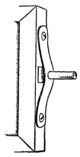
Fig. 153. Trunnion for Mirror.
a pair of small square head bolts about 1/4 of an inch in
diameter and 1 inch long, also two strips of brass 1/2 inch
wide and 3 inches long. In the center of each brass strip we
drilled a hole just large enough to admit the shank of one
of the bolts, and then the strips were fastened with screws
tight against opposite edges of the mirror
frame, with the heads pressed against the
frame and the shanks sticking out at each
side, as shown in Fig. 153. These projecting
shanks served as “trunnions”
(that is, pivots) for the mirror to turn on
when it was mounted in place. After the
trunnions had been set in place we made a
peep hole in the center of the mirror by cutting
out a piece of the wooden back of the
frame and scratching away the silver from
the back of the glass. Only a very small hole was required,
about 1/8 inch in diameter. Great care was taken to have
the unsilvered spot exactly on a line with the trunnions and
149
just half-way between them. This done, we took two sticks
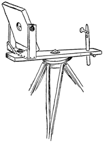
Fig. 154. The Single Mirror Instrument.
of 3/8-inch wood, 1 inch wide and 3-1/2 inches long. In
the upper end of each stick a slot was cut 1/2 inch deep and
1/4 inch wide. Into these slots the trunnions
of the mirror were
placed, and then the
nuts were screwed
tightly on, clamping
the sticks against
the sides of the
mirror. The sticks
were now connected
by nailing a 1/2-inch strip
at the bottom, and braced
by a couple of corner pieces.
This formed a swiveled frame
for the mirror, which was clamped
to the base of the instrument by
means of a bolt 1-1/2 inches long.
The bolt passed through the bottom board of the frame,
squarely under the peep hole of the mirror and through the
baseboard of the instrument near one end. The baseboard
was 2 inches wide, 10 inches long and 3/4 inch thick.
The Sight Rod.
150At the end opposite to where the mirror frame was
swiveled we mounted a sight rod, which was merely a round
stick of wood 1/2 inch in diameter and about 8 inches long.
We cut the stick from one of the rounds
of an old broken chair. The upper end
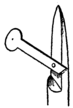
Fig. 155. The Sight Rod.
of the rod was whittled to a point and one
side was flattened as shown in Fig. 155.
Out of a piece of heavy white cardboard
we cut a round disk about 1/4 inch in
diameter, with a shank 1 inch long sticking
out at one side. This was fastened with a
single tack to the flattened end of the rod
in such a position that the point lay exactly against the center
of the disk. The disk could then be turned up or down, to
cover or uncover the point of the rod, as desired. The rod
was fitted snugly into a hole in the
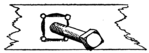
Fig. 156. Nut Set in Baseboard.
baseboard, and could be raised
or lowered to any extent desired,
but we had to provide some sort
of an arrangement for making it
stay where it was put. A small
hole was drilled from the edge of the baseboard through to
the hole in which the rod was fitted. A square socket was
chiseled out around the small hole to receive a nut. The nut
was firmly wedged in and held in place by driving in nails
along the edges. A bolt or machine screw was threaded
151
through the nut, so that its inner end pressed against the
sighting rod. By tightening this screw the rod could be secured
at any height desired.
The instrument was mounted on a tripod similar to the one used for our surveying instrument. To this it was attached by means of a bolt, which passed through the center of the baseboard and the tripod head.
The Screen.
The screen, or shutter, of the heliograph was mounted on
a separate tripod, so as to prevent shaking the mirror when
it was operated. It was made something like a window
shutter. We cut out two slats, each 2-1/2 inches wide and 6
inches long. They were made of hardwood 3/8 inch thick.
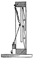
Fig. 157. Section through Shutter.
The upper and lower edges were tapered
down to a thickness of 3/16 inch. Light
nails were driven into the slats at the ends,
and the nail heads were then filed off so
that the projecting ends formed trunnions
for the slats to turn on. The slats were
linked to a connecting rod with double
point tacks. A small double point tack
was driven into the upper edge of each
slat about 1/2 inch from the right
hand end. Then through each of
these tacks we hooked a second double
point tack and drove it into the rod.
The tacks on the rod were placed just 2 inches apart. A
152
substantial frame was then made of 3/4-inch stuff 1-1/2 inches
wide. The frame was square, with an opening that measured
6 inches each way, into which the slats were fitted. Before
nailing the frame together we drilled holes in the side pieces
for the trunnions of the slats to turn in. These holes were
just 1-3/4 inches apart. After the slats had been set in place,
the frame was fastened together and then nailed to a baseboard,
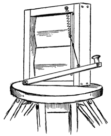
Fig. 158. General View of Screen.
which was fastened
by a bolt to the
tripod. The shutter
was operated by a key
something like a
telegraph key. It
was made of a narrow
stick of wood
hinged at one end to
the lower strip of
the shutter frame,
and a spool sawed
in two was fastened
to the other
end to serve as a
handle for the
key. A string
connected the key with the connecting rod. The slats were
kept closed by a spring, which was fastened at one end to the
connecting rod and at the other to the top of the frame. At
first we used a rubber band for this purpose, but it soon
153
wore out, so we then made a spiral spring out of stiff spring
brass wire by wrapping it around a pencil. When the key
was pressed down the slats would be turned open, as shown
in Fig. 159; but as soon as the key was released the spring
would pull them back again.
Focusing the Instrument.
We were now ready to commence operations with our instruments. The heliograph was set up on the ledge at the top of the cliff. First the disk was turned down, uncovering the point of the sighting rod. Then Bill sighted through the unsilvered spot in the mirror and shifted the rod up and down until the tip end came squarely in line with the door of our straw hut, where Jack was seated, notebook in hand, to take down our message. Reddy stood by him with his wigwag flag to answer back. When the instrument was properly sighted the shutter was set up directly in front of it and the sighting disk turned up to cover the point of the sighting rod. Then came the rather troublesome task of 154 focusing the mirror. The mirror reflected a square panel of light, in the center of which there was a small shadow spot made by the unsilvered peep hole. The object was to get this shadow to fall on the center of the sighting disk. We knew that then the mirror would reflect the sunlight squarely on the straw hut. We found it quite easy to direct this shadow spot to the disk by holding a sheet of paper in front of the mirror six or eight inches away, and following up the spot on the paper until it reached the disk.
Heliograph Signaling.
When at last we succeeded in properly focusing the mirror
Bill pressed the key down three times, sending three quick
flashes to Jack as a signal that he was ready to begin. Reddy
wigwagged back O. K., and then the first heliographic
message was sent from the ledge to
the island. It was a rather mixed-up
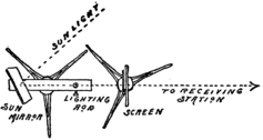
Fig. 160. Top View, showing position of Mirror and Shutter.
message, and
kept Jim and
Reddy wigwagging
back and
forth very
strenuously to
straighten matters
out. It was my duty to keep the mirror focused. As the
sun moved across the sky the shadow spot would move off the
disk, and I had to keep shifting the mirror to bring the spot
back where it belonged. We used the International Telegraph
155
Code, which we had been studying every evening for a week,
but it was many weeks before we learned how to use it
correctly, even slowly. The International Telegraph Code
is as follows:
The three short flashes Bill sent represented the letter S, which stood for the word “signal.” A was formed by a short flash followed by a long flash; B by a long flash followed by three short ones, and so on. The key was held down three times as long for the long flash as for the short one. We found the best way of learning to send the signals properly was to count 1 for each short flash, and for each pause between parts of the letter, and 3 for each dash and for each pause between letters. Between words we counted 6. Thus, for the letter A the key would be down when we counted 1, up when we counted 2, down while we counted 3, 4, 5, and up while we counted 6, 7, 8, for the pause after each letter. It was rather a confusing code, I admit, but in 156 time we mastered it, all but Reddy and Fred, who never would learn, but instead used the wigwag code, letting a short flash stand for 1, a long flash for 2 and a double long flash for 3.
The Double Mirror Instrument.
Our heliographing instrument did excellent service sending
flashes from the cliff to the island, but we couldn’t make
it work very well sending messages from the island to the
cliff, because we had to face almost due north, and then the
sun was nearly always at our backs and couldn’t shine squarely
on the mirror. This led to our building a double mirrored
heliograph the following summer. To begin with, we built
an instrument which was the exact duplicate of our first
heliograph; then, in addition, to fit in the socket of the sighting
rod, we rigged up a second mirror, which was mounted
in exactly the same way as the first. The second mirror was
called the station mirror, and differed from the other, or sun
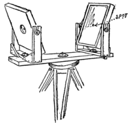
Fig. 161. The Double Mirror Instrument.
mirror, in having a
small patch of white
paper pasted at the
center instead of a
peep hole. When
using this instrument,
we set it up so that the station
mirror faced the ledge, then
by sighting through the hole
in the sun mirror at the
157
reflection in the station mirror we could see just what was
in focus. The station mirror had to be moved until the patch
at its center hid the ledge from view. After that the sun
mirror was shifted until the shadow spot fell on the white
patch of the station mirror. When once the station mirror
was focused, it could be clamped tightly in place by screwing
up the trunnion and swivel nuts. But the sun mirror had to
be constantly shifted to keep the shadow on the patch. Another
way of focusing the mirrors was to stand behind the
instrument with the head close to the station mirror, shift the
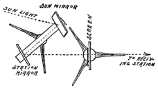
Fig. 162. Top View, showing position of the
Two Mirrors and the Screen.
sun mirror until the entire station
mirror was reflected in it, with
the white patch
squarely over the
unsilvered spot;
then still looking
at the sun mirror,
the station mirror
was shifted until
the reflection of the distant station was brought squarely in
line with the unsilvered spot on the mirror. The station
mirror was now firmly bolted and the sun mirror adjusted
until the shadow spot fell on the paper patch.
As our vacation was drawing to a close, we began to make plans for the Christmas holidays. Our previous Christmas vacation had been so completely taken up with preparations for the trip to Willow Clump Island that we had had no time for the trip itself. We resolved this time to have everything ready beforehand, so that we could spend the entire two weeks in solid pleasure. Our skate sails and snow shoes were stored in the attic, ready for use. If we were to make a trip in the snow we would need a sledge, and then, too, we wanted to make an ice boat. It would hardly pay to build these on the island and then cart them home, so it was decided to break up camp a couple of weeks before school commenced.
Breaking Camp.
Consequently, on the first day of September we gathered up our belongings, corraled our chickens, packed our goods, and the next day started for home. Mr. Schreiner, in response to a letter from the secretary, came down with a large wagon in which the majority of the things were packed. 159 The rest of our luggage was stowed in the scow and the canoes, and these were towed down the canal, as before. We reached home late in the afternoon, tired and hungry. It was a treat to sit at the table again and eat some of Mother’s appetizing dishes. And say, wasn’t that pie great, though! My, how ravenous we were! And then a soft, comfortable bed with spotless white sheets and pillow cases. How soundly we did sleep that night! You can just bet we were all glad enough to get back to civilization, though, of course, no one could have dragged out the confession from a single one of us.
The Ice Boat.
School commenced on the 20th of September that year,
so we hadn’t much time to spare. Work was begun immediately
on the ice boat. Our first ice boat was rather a
crude one. A 2 by 4 inch scantling 14 feet long was
used for the backbone of the boat. The scantling was
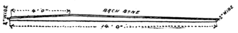
Fig. 163. The Backbone.
placed on edge, and to lighten it and improve its appearance
it was tapered fore and aft from a point 4 feet from the bow
end. The thickness of the ends of the backbone was but 2
inches, as shown in Fig. 163. To the under edge of the
160
backbone, 5 feet from the forward end, a crosspiece was
nailed. This crosspiece was a 1-inch board 6 inches wide
and 9 feet long. Braces were then
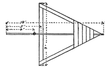
Fig. 164. Frame of the Ice Boat.
run from the ends of the crosspiece
to the forward
and rear ends of
the backbone, and
at the rear end
several boards nailed
across the braces served as a
seat for the boat.
Our next task was to rig up the runners. For these we
used skates, which were so arranged that we could remove
them whenever we wanted to. Three blocks of wood were
used for the runner shoes. Two of

Fig. 165. Runner Shoe.
them were cut from a 2 by 4 scantling
and measured a foot in length. The
third block was only 1 inch thick, but
was otherwise of the same dimensions. The skates were
laid face downward on the blocks with the clamping levers
open; then we marked the places where the clamping jaws
touched the wood and drilled holes at these points. The
forward end of each block was also tapered off to fit flat
against the face of the skate. Then by inserting the jaws
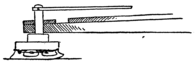
Fig. 166. The Rudder Shoe.
in the holes and closing
the levers, the
skate was clamped to
the block, just as it
161
would be to a shoe. The two 2-inch blocks were bolted to
the ends of the crosspiece, but the third block needed further
attention, as it was to be used for the rudder or steering
runner.
The rudder post was shaped from a block of hardwood
3 inches square and 10 inches long. Two inches from the
lower end saw cuts were made in
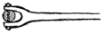
Fig. 167. The Tiller.
the side of the block to a depth of
3/4 inch. Then with a chisel the
sides were split off, forming a large
pin with a square shank 8 inches long. Next the corners of
the shank were cut off, rounding it to a diameter of 1-1/2
inches. The runner block was fastened securely to the head of
the rudder post with screws. A 1-1/2-inch hole was now drilled
into the backbone at the stern end to receive the rudder post.
A tiller was next cut out of a 1-inch board to the shape
shown in Fig. 167. A slot was
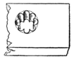
Fig. 168. Drilling the Mast Step.
cut in the end of the tiller, and the
latter fitted snugly over the top of the
post, where it was held in place by
screws threaded in through the sides.
The mast of our boat was a pole
8 feet long, tapering from a diameter
2 inches at the base to 1-1/2 inches at the top. A step for the
mast was cut from a 2 by 4 block 8 inches long. A 2-inch
hole was drilled into the face of this block. We had no drill
large enough to bore this hole, but accomplished the same
result by drilling eight 1/2-inch holes inside of a 2-inch circle
162
(Fig. 168), and then used a chisel to cut off the projecting
pieces. The mast step was firmly bolted to the backbone
at its thickest part, that is, just four feet
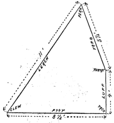
Fig. 169. The Mainsail.
from the forward end. The mast
was braced with stay ropes
stretched from the top to the
forward end of the backbone
and to the ends of the crosspiece.
A 9-foot pole,
tapering from 1-1/2 inches
to 1 inch in diameter,
was used for the
boom of the
mainsail, and for
the gaff we used
a 6-foot pole of
the same diameter.
The dimensions of the mainsail are given in Fig. 169.
For mast hoops we used curtain rings. Five were attached
to the sail along the luff, and one was fastened with a piece
of leather to the end of the gaff. We used a different scheme
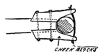
Fig. 170. Jaws of the Boom.
for holding the boom to the
mast. The forward end of
the boom was flattened at the
sides and a couple of cheek
blocks were bolted on, forming
jaws of the shape indicated in
163
Fig. 170. The jaws were whittled out to fit nicely around
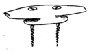
Fig. 171. A Cleat.
the mast, and were kept from slipping off by a piece of rope
passed around the mast and threaded through the ends of
the cheek blocks. Half a dozen small pulley blocks were
now procured, of the type used on awnings. A rope called
the throat halyard was strung from the throat or forward end
of the gaff through a pulley block near the top of the mast,
and led down to the backbone, where it was “belayed,” or
wrapped around a cleat. The cleat, which was whittled out
of a stick of wood, was made in the
form indicated in Fig. 171. A short
length of rope was strung through a
pulley block and tied with some slack
to the upper end and to the center of
the gaff. This rope is called a
“bridle,” and to the pulley block on
this “bridle” a rope was attached called the “peak halyard.”
The peak halyard was passed through a pulley
block at the top of the mast, and belayed on a cleat at the
side of the backbone. For the main sheet (that is, the rope
used for guiding the mainsail) two pulley blocks were
fastened to the backbone, one just in front of the seat and
the other a few feet further forward, and two more were
lashed to the boom, midway between these blocks. The
sheet was fastened near the aft end of the backbone and then
strung through the blocks in the order illustrated, the free
end of the sheet being brought back to the seat, where a cleat
was provided, to which it could be secured when desired.
164The jib-sail was now cut out to the dimensions given in
Fig. 172. The foot of the sail was lashed to a jib-boom
3 feet 4 inches long. The jib-boom was attached
to the backbone at its fore end by means of a
couple of screw eyes. The eye of one of
these was pried open, linked through the
other and then closed again. One of
the screw eyes was now screwed into
the head of the jib-boom and the other
was threaded into the end of the backbone.
The upper corner or “head”
of the jib was tied to a jib-halyard, which passed through a
block at the top of the mast, and was secured on a cleat on the
backbone. On the jib we used two sheets. They were attached
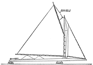
Fig. 173. The Ice Boat Completed.
to the end of the jib-boom and passed on opposite
sides of the mast through
blocks on the crosspiece to
the stern of the boat,
where separate cleats
were provided for
them.
This completed our ice boat, and a 165 very pretty little boat she was. It was with great reluctance that we furled the sails, unstepped the mast, and stowed away the parts in our attic until old Jack Frost should wake up and furnish us with a field of smooth ice.
The Sledge.
Our sledge was patterned after a picture of one used by
Peary in one of his Arctic expeditions. First we got four
strips of hickory 1 inch thick, 1-1/2 inches wide and 8 feet
long for the runners and side rails. Beginning 18 inches
from the ends, each stick was tapered gradually to a thickness
of 1/2 an inch. Then we made eight spreaders or
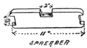
Fig. 174. A Spacing Block.
spacing blocks, each 1-1/2 inches
thick, 2-1/2 inches wide and 11
inches long. In each end a notch
1/2 inch deep was cut to receive the
runners and side rails. In the edge
of each block, midway of its length,
a slot 1 inch deep was cut to receive the cross sticks of the
sledge. First we nailed the runners and rails to the blocks,
fastening them with screws, spacing the blocks 16 inches
from the ends, and 20 inches apart from center to center.
Then we bent the ends of the rails and runners together,
fastening them with bolts, as in Fig. 175. Four crosspieces,
or floor beams, were cut out of a 1-inch board, each 2 inches
wide and 30 inches long. These were fitted into the slots
in the space blocks and secured with screws. A cross stick
166
was also fastened between the rails and runners at the forward
end. On the floor beams we nailed a flooring of
1/2-inch slats, 2 inches wide and 6 feet long. At the rear
end these slats projected 8 inches beyond the last space block
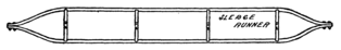
Fig. 175. The Runners and Rails Spaced Apart.
and over them a cross slat was nailed. A stick of hickory
4-1/2 feet long was soaked in hot water, as described on page
39, and was bent to an U-shape. The ends were then fitted
over the first cross stick, and under the first floor supports,
and securely nailed in place. Another stick of hickory 6
feet long was similarly bent, and the ends slipped over the
rear cross slats and fitted against the rear space blocks, in
which position the stick was securely nailed.
It was our intention to shoe the runners
with strips of brass, but these were not
procurable in our village, and we had no time to go down to
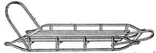
Fig. 176. The Sledge.
Millville. However, the village blacksmith came to our
rescue and shod our sledge with sleigh runner iron.
167We had planned to make two more devices for our winter sports–a toboggan and a peculiar looking contrivance called a “rennwolf,” a picture of which Dutchy happened to unearth in one of his father’s books. Unfortunately Bill and I had to return to school before either of these was completed. However, the work was entrusted to Reddy, who was quite handy with tools, and Jack, who was made secretary pro tempore, took notes on the work.
The Toboggan.
The toboggan was made of light flexible hickory boards,
1/4 of an inch thick, 6 inches wide and 8 feet long. Three
of these boards were used, and they were fastened together
with cross sticks or battens, about 3 inches wide and 1/2 an
inch thick. There were six of these battens spaced about
15 inches apart, and secured to the floor boards with flathead
screws introduced from the under side and countersunk so
that the heads would not project below the bottom of the
toboggan. At the forward end we screwed on a head piece
of oak, 3/4 of an inch thick, 1-1/2 inches wide and 20 inches
long. The head piece was fastened to the under side of the
boards, so that when they were curved up into a hood it
would lie on top. The ends of the head piece, which projected
1 inch each side of the boards, were notched to hold
the rope, which was tied fast after the boards had been
steamed. The boards were steamed by wrapping them in
burlap for a distance of 2 feet from the forward end, and
168
pouring boiling water over them, as was done with the
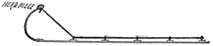
Fig. 177. Tying Down the Head Piece of the Toboggan.
snow shoes (page 39). Before bending the boards we had
fixed screw eyes in the ends of each batten, except the forward
one; a rope had been strung
through these screw eyes and the
ends were now tied to the head piece and drawn tight so as
to bend the boards into a graceful curve. In this way the
ropes were of service not only for curving the front end into
a hood, but also for side rails, to hold on by when shooting
swiftly around curves.
The Rennwolf.
The runners of the rennwolf were made of hickory strips, 1 inch thick, 2 inches wide and 8 feet long. At their forward ends these strips were tapered down to a thickness of 1/2 an inch and curved upward. About 30 inches from the rear end of each runner an upright post was nailed. The post 169 was 3 feet long and was braced by a diagonal brace 24 inches long, as shown in Fig. 179. A tie bar was nailed to the post about 6 or 8 inches from the bottom and connected with the forward curved end of the runner.
The two runners were now placed parallel to each other about 18 inches apart, and connected by four cross bars, one at the forward end, and three on the upright posts, in about the positions illustrated. The upper cross bar was extended 6 inches beyond the posts at each side, and served as a handle for guiding the queer craft. An 18-inch square board was used for the seat of the rennwolf. It rested on the second cross-bar of the post about 12 inches from the runners, and the forward end was supported on legs nailed to the tie bars. On each runner back of the posts a loop of leather was nailed, large enough to receive the toe of one shoe.
When using this odd sled one foot would rest on the runner with the toe in the strap, and by kicking out against the snow or ice with the other foot the rennwolf would be made to spin along at a rapid rate. Of course, when coasting both feet would rest on the runners and the sled was steered by an occasional side push at the right or left. Owing to the 170 great length of the runners the rennwolf would easily ride over uneven surfaces and thin spots in the ice.
Ice Creepers.
In order to provide a better hold for the propelling foot, we fastened around the toe a strap of leather, through which a number of long tacks projected. Their sharp points would stick into the ice, and prevent the foot from slipping. The seat of the rennwolf was convenient for carrying a coat or any light luggage, and it was often used to give a friend a very exhilarating ride.
I am afraid we were not very glad to get back to school that fall. It seemed very hard to give up the sport we had been having, and our heads were brimful of new schemes which we could hardly wait to put into practice. But we soon learned that there are many things that could be done during recreation hours at school. We had intended building a cave on our island that summer, but our vacation came to an end before we got around to it. There seemed no reason why we shouldn’t dig one in the woods at the back of the schoolhouse.
A Cave-in.
Bill had read somewhere that if you dig a cave under a tree the roots of the tree will support the ground on top and make a natural and substantial roof. It sounded very reasonable, we thought; in fact, we never questioned the truth of the statement, because we had somehow gotten the notion that books were never wrong, and that whatever was set up in type must surely be so. But events proved that the man who wrote that book had never attempted to build a cave in the manner he described, at least not in the loose, 172 sandy soil of south Jersey. A large spreading cedar was selected as the tree which should support the roof of our cave. It was situated on a mound at the edge of the woods. First a passageway, or ditch, was dug at the bottom, and then we begun tunneling in the side of the mound under the roots of the tree. For a while the ground above held, and our tunnel had reached a length of about four feet, when suddenly, without the slightest warning, the sandy soil gave way and we were engulfed. Bill, who was furthest within the cave, was almost entirely covered, while I was buried to the shoulders. A crowd of boys came to our assistance and dug us out. Poor Bill was almost smothered before they scooped the sand away from around his mouth and nose. The boys made slow work of it, having to dig with their hands and a couple of shingles, because the two spades we had were buried with us at the bottom of the cave.
Of course, this little episode gave us a scare, but it was only temporary. We swore every one to secrecy, so that Mr. Clark, the principal, wouldn’t hear of the mishap and suppress any further cave building. It was obvious that the only roof we could depend on for our cave would be a wooden roof. If we had been at Willow Clump Island we would have gotten any amount of slabs from the lumber mills across the river.
One of our schoolmates, a day scholar, came to the rescue. His name was Chester Hill, a little bit of a chap, about the shortest for his age that I have ever seen. His name was so at variance to his size that we called him “Hillock,” for 173 short. Now Hillock lived on a farm about eight miles from school, and used to drive in every day on a farm wagon. He had helped us dig the cave under the cedar tree, and when he learned that we would need some lumber to build a safe cave, he told us that he had an uncle who owned a lumber mill on the Morris River, from whom he was sure we could get all the slabs we wanted. Of course, we were delighted, and laid our plans for an elaborate cave house. Hillock promised to be on hand on the following Saturday afternoon with his load of lumber.
Excavating for the Cave.
We immediately set out to make the necessary excavation. The side of a bushy knoll was chosen as a suitable site. First we carefully transplanted the bushes that grew in the square we had marked out for the cave, and cutting the sod into squares, piled it all neatly to one side. Then we shoveled away the top-soil and heaped it up for future use. After that we dug away the sandy subsoil. The cave proper we planned to make about 8 feet by 10 feet, with a passageway 2 feet wide and 6 feet long, leading in from a large bush at the base of the knoll. Our excavation was therefore somewhat T-shaped (see Fig. 182). At the deepest part we had to dig down about 10 feet.
174The digging was all done by Saturday, when Hillock
pulled up with a big load of slabs. Slabs are a very unsatisfactory
kind of wood for most purposes. Being the outside
cut, they are usually very irregular and weak in spots. In
many places they are almost clear bark. Of course, had our
pocketbooks permitted, we would have used stout scantlings
for the corner posts of our cave house and substantial boards
for the walls, roof and flooring, but we had to be content
with materials at hand. Eight of the best slabs were selected
for our corner posts; four of them we cut to the length of
8 feet and the others to a length of 6 feet. The long slabs
were set up at the rear of the cave, two at each corner, one
flat against the rear wall, with its edge buried in the corner,
and the other against the side wall, with its edge tight against
the rear slab, as in Fig. 183. The same was done at the
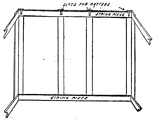
Fig. 183. Framework of the Cave.
175
forward corners
with the shorter
slabs. A couple
of slabs were now
set up on each
side of the
passageway, and
a corresponding
pair against the
rear wall. The
upper and lower ends of the uprights were then connected
with slabs, called stringpieces.
The sides were now boarded up with upright slabs nailed
to the stringpieces. An opening 3 feet 6 inches high was left
in the forward wall for a passageway. Several slabs were
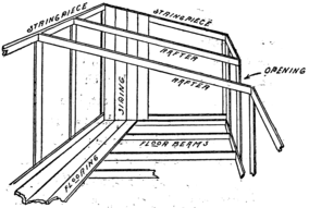
Fig. 184. The Siding and Flooring.
now placed on the edge across the bottom of the cave, to
176
serve as floor beams, upon which a flooring of slabs was
laid. Next the rafters were set in place, one on each upright
slab. Slots were cut in the ends of the uprights to receive
the rafters, which were slabs placed on edge. As the forward
uprights were 2 feet shorter than the rear ones, the
rafters were given a good slant, so that the roof would
properly shed any water that might soak in through the
ground above.
The roof was laid on the same way that we had made the roof of our tree house; that is, a slab was first nailed at the forward end of the rafters with its edge projecting far enough to make a good eave; then the second slab was nailed on, with its edge overlapping the first, and a third with its edge overlapping the second, and so on with the rest. At the rear end of the roof a hole was cut, into which we fitted a piece of stovepipe. We didn’t plan to have a fire in the house, but set the stovepipe in place to provide the necessary ventilation. As the pipe had an elbow in it, there was no danger of rain or dirt falling through it. The upper end of the stovepipe was concealed among some rocks at the top of the knoll.
A suitable flooring was now laid in the passageway, and the sides were boarded up to a height of 2 feet from the 177 floor at the entrance to a height of 3 feet 6 inches at the inner end. A roof of slabs was nailed on, and then we were ready to cover our slab house with dirt.
Covering the Cave.
We avoided piling on the dirt very deep, because there was danger of breaking in the roof with a heavy load. A thin layer of sand covered with the top-soil brought up the level to about that of the rest of the knoll. Then the sod was laid back in place and well watered, and the few bushes planted back in their original positions. Our sodding should have been done in the spring for best results. The frost soon killed the grass, and the bushes withered away. But a few cents’ worth of grass seed was sowed in, and in time gave the knoll a very natural appearance. A bush at the bottom concealed the entrance of the cave, so that no one who was not in the secret would have suspected that beneath that innocent looking knoll were gathered the members of the 178 “Big Bug Club.”
The Big Bug Club.
Of course, we had to organize a secret society, to occupy our subterranean dwelling. In that I fear we overstepped the rules of the school. Of course, Mr. Clark knew of our cave, in fact he visited us there once, lowering his dignity sufficiently to squeeze into the narrow passageway, and playing Bill a game of chess at our club table. He seemed 179 quite pleased with our work, and complimented us very highly on the masterful way in which we had built the underground house. We told him that we had organized a club of the older fellows to play indoor games and have occasional spreads, but we did not tell him that most of our spreads were held at the dead of night, when there was no moon and the stars were hidden by clouds. At 10 o’clock each night the bell rang for us to turn out our lights, and after that the six members would each, in turn, keep a half-hour watch, that is, first one would sit up and try to keep awake for half an hour, after which he would waken the next fellow, who at the end of a half hour would rouse the third, and so on, until 1 o’clock, when the sixth watcher would wake up the entire club. Then we would all creep out the back window in the hall, onto the roof of the rear annex of the schoolhouse, and thence climb down a rope ladder to the ground.
Midnight Banquets.
I suppose we could have just as easily have tiptoed downstairs and out the back door, but it would have spoiled the romance of it all. The absolute stillness and the pitch-black darkness of the night were awe-inspiring. The roll of a pebble or the crack of a twig under foot would set us all atingle as we stole out to our cave house. Sometimes the night was so black that we could hardly find the entrance of the cave. Once inside, in the light of a few candles, the 180 nervous tension was relieved, and we reveled in a banquet of cold victuals and dainties, purchased out of the monthly club dues. Our meetings in the cave lasted scarcely half an hour. In fact, the meeting, and even the banquet, were mere incidentals. The main enjoyment consisted in stealing out to the cave and back again, always at the risk of getting caught. Usually when we got to bed again we would be too excited to fall asleep right away, and when we did finally drop off our sleep was so sound that several times the breakfast bell caught one or more of us still napping.
The Club Pin.
The only other charm our secret club afforded was the wearing of a mysterious club pin. It was a silver beetle, with the letter G engraved on the head and the letter B on the body, while down the center of the back was the letter I (see Fig. 187). In public we called ourselves the G. I. B.’s, but it was only the initiated members who knew that these letters were to be read backward, and, with the beetle on which they were engraved, signified the “Big Bugs.” Of course, we had some secret signs and signals, a secret hand grasp, a peculiar whistle as a warning to run, another meaning “lie still,” and a third signifying “all is well.”
The Combination Lock.
181We found it necessary to close the entrance of our cave
with a door fastened with a padlock, so as to keep meddlers
out. The entire school had watched us build the cave house,
and, of course, knew just where our entrance lay. Then, in
addition to the outer door, we put in another one, half-way
down the dark passageway. On this Bill rigged up a simple
combination lock which would baffle any one who managed
to pick the padlock. This inner door opened outward. It
was hinged to the floor of the passageway, and swung up
against a frame set in the passageway. At the top was a
board whose lower edge lay flush with the edge of the door
when it was closed. For the combination lock we used a
couple of spools, each with one head cut off and the central
hole plugged up with a stick of wood. In the floor and the
top board of the frame, holes were drilled just large enough
for the shanks of the spools to fit snugly in them. Next we
made a trip to a hardware store for a file and a couple of
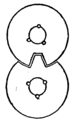
Fig. 188 The Notched Washers.
large copper washers, about 1-1/4 inches in diameter. The
washers were fastened to the inner ends of the spools after
they had been pushed through the hole. The washer on
the door came just to the edge of the door, while the other
extended below the door frame and lapped under the door
washer. Then in the edge of the washer on the frame a
notch was filed, while in the other washer two notches were
filed, so as to leave a tooth which fitted snugly into the notch
of the first washer (see Figs. 188, 189). The door was
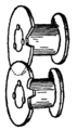
Fig. 189. Washers Fastened on Spools.
182
locked by turning both the washers until the notch and tooth
came in line with each other, then pushing the tooth through
the notch, and turning the washers so that the frame washer
hooked over the door washer. Then the door could be
opened only when the tooth and notch were brought in line.
On the head of each spool
we pasted a disk of white
cardboard, the edge of which
was graduated, as in Fig. 190.
Then we had a secret combination,
say 11-19, which
meant that when the spools
were turned so that the number
11 on the door spool came
in line with the number 19 on the frame spool the tooth and
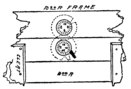
Fig. 190. The Combination Lock.
notch would be in line, and the door could then be opened.
Of course, this combination was known to the members of
the club only, and any one outside who tried to open the
door might have tried for some time without bringing the
tooth and notch into line with each other. Occasionally
we changed the combination by loosening the screws which
held the washers, and turning them
so that the notch and tooth came
opposite different numbers on the
dials. This was done so that if
any one should chance to learn our
combination he could not make use
of it very long.
“Hello, Dutchy! What in thunder have you got there?”
It was Bill who spoke. We were on our way home for the winter holidays, and had been held up at Millville by Reddy Schreiner, who had informed us that Dutchy was down by the river with the boat to give us a sail up to Lamington.
A vision of a fleet ice boat skimming up the river at express train speed swam before our eyes. But the next moment, as we turned the corner into River Street, we were surprised by the sight of our old scow just off the pier at anchor, and in open water. It was rigged up with a jib and mainsail, which were flapping idly in the wind. It had also been altered by decking over the top, with the exception of a small cockpit, evidently for the purpose of keeping out the water when she heeled over under the wind. We were disappointed and quite annoyed at not finding the ice boat on hand; furthermore, our annoyance was considerably heightened by Dutchy’s broad grin of evident delight at our discomfiture. “The river wasn’t all frozen over,” he explained, “and we couldn’t bring the ice boat down, so we rigged up the scow and she came down splendidly.”
A Sail in the Scow.
184There was nothing to do but to jump in, though I, for one, would have taken the train in preference had there been one inside of two hours. Dutchy, however, seemed to be in a surprisingly good humor, and kept up a lively chatter about things that the club had made in our absence. The skis, which have already been described on page 42, had been built under Reddy’s guidance, and they had already used them on Willard’s Hill, coasting down like a streak and shooting way up into the air off a hump at the bottom. Then there was the toboggan slide down Randall’s Hill, and way across the river on the ice.
Our Craft Strikes the Ice.
Dutchy talked so incessantly that we hadn’t noticed the field of ice which we were nearing. Just at this point Bill turned around with an exclamation.
“Here, Dutchy, you crazy fellow, where are you going to? Hard to port, man–hard aport–or you will crash into the ice!”
But Dutchy only grinned nervously.
“I tell you, you will smash the boat!” Bill cried again, making a dive for the steering oar; but just then the boat struck the ice, and both Bill and I were thrown backward into the bottom of the boat. But the boat didn’t smash.
185There was a momentary grinding and crunching noise, and, much to my surprise, I found that the old scow had lifted itself clean out of the water, and was skating right along on the ice. Then Dutchy could control himself no longer. He laughed, and laughed, as if he never would stop. He laughed until the steering oar dropped from his hands, and the old scow, with the head free, swung around and plunged off the ice ledge with a heavy splash into the open water again. Then Reddy, who was almost equally convulsed, came to his senses. “Now you’ve done it, Dutchy; you’re a fine skipper, you are! How do you expect to get us back to shore again?” The steering oar was left behind us on the ice, and there we were drifting on the open water, with no rudder and no oar to bring us back.
The Scooter Scow.
The only thing we could do was to wait until the wind or current carried us to the ice or land. In the meantime Dutchy, who had suddenly sobered down when we took our water plunge, explained how he had rigged up the scow to travel both on ice and on water. He called the rig a sled boat, but the name by which such a rig is now known is a “scooter.” It was Dutchy’s idea primarily, but Reddy had engineered the work. Along the bottom of the 186 scow two strips of hickory had been nailed to serve as runners. The hickory strips had been bent up at the forward end, as shown in Fig. 191. Each runner was shod with a strip of brass, fastened on with flathead screws, which were countersunk, so that the heads should not project below the brass. This virtually made a sledge out of the old scow, and didn’t spoil it for use on the water.
A Sprit Sail.
A sprit sail and
jib were rigged up.
The dimensions of
these sails, which
were taken from a
book in Mr. Van
Syckel’s library,
are given in the
illustrations. A
sheet of heavy
muslin was made
to measure 7 feet
square, as indicated by dotted lines in the drawing; then the
corners were cut off along the full lines shown in the illustration.
The edges were now hemmed all around, and the lower
edge of the sail was lashed to a boom, 7 feet 6 inches long.
To the luff were attached a number of mast rings, which were
187
slipped over a stout mast projecting about 5 feet 6 inches
above the deck of the boat. The peak of the sail was held
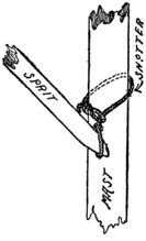
Fig. 193. The Snotter.
up by a spar called a sprit. The sprit was sharpened at each
end, and the point at the upper end was inserted in a loop of
heavy cord fastened to the peak of the sail,
while the lower point of the sprit rested in
the loop of a rope on the
mast, called a “snotter.” The
snotter was a short piece of rope
with a loop at each end. It was
wrapped around the mast, as shown
in the drawing, with one loop holding
it in place, like a slip knot, and the other
supporting the end of the sprit. A single
halyard was used to raise this sail. It was
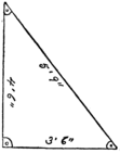
Fig. 194. Jib-sail of Scooter Scow.
attached to the boat and passed over a block
in the mast. When raising the sail it was first
partly hoisted, then the sprit was hooked in
the loop and the snotter, after which the
throat halyard was drawn taut. Then the snotter
was pulled up the mast as far as it would go, flattening
out the sail. The jib-sail was made
out of the large corner piece left when cutting
the mainsail. The dimensions of
the jib-sail are given in Fig. 194.
It was such a small sail that no
boom was used with it. In place of
a rudder the steering oar had to be
188
used. This was made of a rake handle with a large trowel
blade fastened to the end of it. The sharp blade cut into the
ice, and so steered the scow when it was running as an ice
boat, and in the water the blade offered sufficient resistance
to act as a rudder.
Scooter Sailing.
But to return to our sail home to Lamington, we were not out on the open water long before the current carried us back to the ice ledge. Reddy jumped off and soon returned with the steering oar; then we proceeded on our way homeward, now in the water and now on ice. Once or twice the scow was unable to climb out of the water, because she had not sufficient headway, and was clumsy and heavy with four boys aboard. Then we had to push off until we could get a sufficient start. It struck me that while Dutchy was quite clever to think of such a rig, yet it was very clumsy and capable of much improvement. Bill wasn’t saying very much all this time, and I could see he was doing a lot of thinking. Evidently he was planning some improvement, but Bill was a very considerate fellow, and did not want to spoil Dutchy’s pleasure just then by telling him how much better a scooter he might have built. It wasn’t until after supper, when a meeting of the S. S. I. E. E. of W. C. I. was called, that Bill came out with his scheme.
A Meeting of the Society.
189“Why not mount the sailing canoe on runners, instead of the scow? You would have a very light rig then, and it would sail like a streak.”
“Mr. President,” said Reddy, “your plan sounds first-rate, but how are you going to fasten runners onto the canoe?”
“I’ve thought all that out,” replied Bill. “If we can only get hold of a pair of sleigh runners it won’t take long to rig up the sled boat.”
Dutchy, who had looked rather crestfallen at a suggestion of an improvement on his pet invention, now suddenly brightened up.
“I know where we can get the sleigh runners!” he exclaimed. “Dad has an old ramshackle sleigh in the barn that is just falling to pieces with dry rot. I’ll ask him for it to-night.”
“Do you think you can get it?” inquired Bill.
“I guess so,” Dutchy answered, rather doubtfully. “But say, suppose we send a delegation to see him about it?”
An Interview with Mr. Van Syckel.
This was agreed upon, and in the morning, as soon as breakfast had been downed, the entire society marched in a body into Mr. Van Syckel’s library. I was appointed spokesman, with Bill to back me, while the rest of the party 190 were strung out behind, with Dutchy bringing up the rear. Mr. Van Syckel was not the man to take much interest in boys’ work, but we happened to strike him at the right moment, and before our interview was over we had told him all our experiences of the summer before and all our plans for the future. Then we did a good turn for Dutchy, too. Mr. Van Syckel had always considered his boy a “know-nothing,” and was very much surprised to find that he had invented the scooter scow. Why, he actually seemed proud of his son, much to Dutchy’s embarrassment. After that there was no trouble about getting the sleigh runners, and Mr. Van Syckel forgot the objections he had offered at first.
The Scooter Canoe.
Naturally we were very much elated at our success, and straightway made for the barn, where we began operations on the scooter canoe. The sleigh was an old-fashioned affair, with rather broad wooden runners. First we removed the body of the sleigh, and then the runners were cut down to a height of about 15 inches. We spaced them apart about 28 inches, and connected them with four crosspieces at the 191 top. The runners were now placed over our larger canoe, with forward ends about on a line with the mast, and the crosspieces were fastened with screws to the gunwales. As an additional security, a pair of crosspieces were now run under the canoe at each end and fastened with screws to the keel. At the bow the keel was shod with a strip of brass. The rudder was taken off the boat, and an oar lock was fastened to the stern to hold the steering oar. In place of lee boards we nailed a couple of thin boards over each 192 runner, as shown in the drawing. We were in a hurry to finish this, as our vacation was short, so we used on the scooter canoe the sails that we had made for our ice boat. This required a bowsprit, but as we had little time to spare we used the jib-boom of the ice boat, nailing it to the deck beam of the canoe. We decided that the jib-sail could be used without a boom, as we had done with the scow. The mast was braced by stays attached to the ends of the runners and bowsprit. This spread of canvas was far greater than that originally provided for sailing the canoe, but the heavy runners on each side helped to keep the boat on even keel, and then to further balance the sail a board was nailed across the aft end of the boat. This overhung the runners about 18 inches each side, and in a strong wind we could sit out on the windward end of this board, thus preventing the scooter from heeling over too far.
As soon as our scooter canoe was completed we prepared for the long-planned winter expedition to Willow Clump Island. The weather conditions were ideal. We had had ten days of steady cold weather, which had followed a heavy fall of snow, so that we could tramp up the island on snow shoes, or we could use our scooter canoe and scooter scow on the river. It was out of the question to use our skate sails or the ice boat on the river, and the canal would be serviceable only in case the wind should blow from a southerly quarter. But we stowed them on the sledge for use on Lake Placid.
On the Tuesday morning following Christmas we made the start. Bill in the scooter canoe and Dutchy in the scooter scow sailed up the river, and the rest of us, on snow shoes, took the tow path of the canal, hauling the sledge along. We carried provisions for a week and a good supply of blankets. The island was reached without mishap, except that Dutchy had to be helped several times in dragging the heavy scow around the rapids. Bill reached the island long before we did, and after unloading the canoe came racing back under a stiff breeze for a second load. Then he took his turn at 194 hauling the sledge, while Reddy sailed the reloaded scooter canoe up to the island.
Willow Clump Island in Winter.
We brought no tent with us, as we expected to take up our quarters in the straw hut. When we reached the hut we hardly recognized it. It was almost completely covered with snow and looked like an Eskimo house. The snow had drifted well up over the north side, completely closing the entrance. We had to set to work at once with a shovel and open up a passageway, and then we had to shovel out a large pile of snow that had drifted into the hut from the open doorway.
Kindling a Camp Fire.
In the meantime Jack scoured the island for some dry wood. In this he was not very successful, because everything was covered with snow, and when he tried to kindle a fire in the open space in front of our hut he found the task an exceedingly difficult one. Unfortunately we forgot to bring the oil stove with us, and the prospect of something warm to eat was exceedingly remote. We hadn’t yet learned the trick of building a camp fire in wet weather. After exhausting our stock of paper Fred and I started over to Lumberville for several newspapers and a can of kerosene. We went to old Jim Halliday’s, who had befriended us on 195 one or two occasions the previous summer, and made known to him our troubles.
“What! A can of oil to build yer fire with? Well, ye won’t git it from me. I know a man as got blowed up apourin’ oil on a fire. Why, shucks, boys, you don’t need no oil ner paper nuther on that there island. Its chuck-full of silver birch trees, and there ain’t no better kindlin’ than birch bark.”
Birch bark! Why, yes, why hadn’t we thought of that? We had used it for torches the summer before and knew how nicely it burned. So back we skated to camp, and then, peeling off a large quantity of bark from the birch trees around us, we soon had a rousing big fire in front of the hut.
The Outdoor Fireplace.
But there were more things to be learned about open fires. In our summer outing Jack had done most of his cooking on a kerosene stove, and he soon found that it was a very different matter to cook over an unsheltered fire. The heat was constantly carried hither and thither by the gusts of wind, so that he could scarcely warm up his saucepans. We had to content ourselves with cold victuals for the first meal, but before the next meal time came around 196 we had learned a little more about fire building. Two large logs were placed about 10 inches apart, and the space between them was filled in with pieces of bark and small twigs and sticks. The back of the fireplace was closed with stones. One touch of a match was enough to kindle the fire, and in a moment it blazed up beautifully. The logs at the sides and the stones at the back prevented the wind from scattering the flames in all directions, and a steady draft poured through the open end of the fireplace and up through the heart of the fire. The side logs were so close together that our cooking utensils could be supported directly on them.
A Stone-paved Fireplace.
The following summer we continued our open fireplace
experiments. Instead of using logs we drove stakes into
the ground, forming a small circular stockade about 2 feet
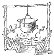
Fig. 198. A Stone-paved Fireplace.
high and 3 feet in diameter. A paving of small stones covered
the floor of the fireplace, and a lining of stones was laid
against the wall. The stakes were driven in on a slant, as
illustrated in Fig. 198, so as to better support the stone
lining. A break in the stockade at one side let in the necessary
draft. Two of the stakes on opposite sides of the fire
were made extra long, and were crotched at their upper
ends. They served to support the cross stick from which our
kettles were hung. This form of fireplace was more satisfactory
for baking than the one in which logs were used for
the side walls, because the stone lining retained the heat much
197
longer. To bake biscuit, a pot of beans, or the like,
the ashes would be drawn away from the stone paving
and the pot placed directly on the hot stones, after which
it was covered with hot
embers and ashes.
A Cold Night in the Hut.
But to return to our experiences on the island. We found it very cold on the first night in the hut. We were afraid to build a fire inside lest the straw thatchings would catch fire, and so we huddled together in the corner, rolled up tightly in our blankets. But it was cold, nevertheless. We had no door to close the opening into the hut, and instead had piled up branches of cedar and hemlock against the doorway. But a bitterly cold northwest wind was blowing down the river, and we couldn’t keep warm, no matter what we did. Most of the boys were ready to go right home, but we stuck it out until the morning, and then after we had toasted ourselves before a blazing bright fire, and had eaten a hot breakfast, we forgot much of the discomfort of the night and were ready for more “fun.” We thought we would spend the next night in our tree house, and so, right after breakfast, 198 we packed up our blankets and some provisions and started for the Jacob’s Ladder.
Mountain Climbing.
Each fellow was provided with a pair of ice creepers of the same sort as we had used in connection with the rennwolf (see page 170). In addition to this each boy was provided with a home-made alpine stock, consisting of a stout wooden stick in the end of which a large nail was driven and the head filed off. Thus equipped we came to the foot of the cliff, and much to our delight found it one mass of ice from top to bottom. Now was our chance to try some Swiss mountain climbing. Bill took the lead, with an old hatchet in his hand, to hack out any necessary footholds in the ice wall, and the rest of us strung out behind him tied to a long rope, each boy about 10 or 12 feet from the one ahead. Bill cautioned us to keep our distance, holding the rope taut in one hand, so that if a fellow stumbled he could be kept from falling either by the one in front or by the one behind.
“Besides,” he said, “if the rope drags on the ice, it is liable to be cut or worn so that it will break when any strain was put on it.”
Now, one would think from all these precautions that we were launched on a perilous expedition. That was the impression we were trying to make on ourselves, though, as a matter of fact, any one of us could have climbed the cliff unaided and without any ice implements if he had used 199 ordinary care not to slip on the ice-clad ladder rounds or the snow-covered ledges.
A Poor Shelter.
The climb was without mishap and we reached our tree house, only to find it so badly racked by storm and weather that it was clearly out of the question to attempt to spend the night there. The wind howled around the house and whistled through dozens of cracks and chinks that had opened in the walls. All that we could do, therefore, was to turn back to the island and make the best of our straw 200 hut again. On the way, however, we stopped at Lumberville for some straw to be used for bedding. The afternoon was spent sailing around on Lake Placid and the large smooth stretch above the island.
A Costly Camp Fire.
After supper Bill and Reddy went into the hut to arrange the straw bedding, while the rest of us gathered wood for a huge bonfire in front of the hut. The wind was blowing right down the river and we expected it to carry the warmth of the fire into the hut. The fire was built some distance in front of the doorway, so as to prevent the hut from catching fire. But we had evidently miscalculated the strength of the wind, for no sooner was the fire fairly started than a shower of flaming brands was blown right into the hut. In a moment the straw blazed up, cutting off all escape for Bill and Reddy. Fortunately the framing was not strong and the frost had loosened up the foundations, so that a few frantic kicks opened an exit in the rear of the hut just in time to save our comrades from cremation. Once it was fairly started we were powerless to put out the blaze until the hut was ruined. The snow that covered the walls checked the fire somewhat, but the thatching burned from the inside, melting the snow and dropping it suddenly into the flaming straw bedding on the floor. As we sat in a gloomy ring about the camp fire, watching the tongues of flame play about the charred ribs of our hut, we had reason 201 to be thankful that the wind had played its pranks before we turned in for the night. What a risk we had run of being all burned to death! It made me shudder to think of it. Well, our hut was burned. What next? That was the question put before the society.
“Might build a snow hut,” suggested Dutchy.
“Now, be sensible,” answered Reddy. “We can’t build a snow hut in five minutes.”
“The best plan,” I volunteered, “would be to go over to Jim Halliday’s and ask him to let us sleep in his barn.”
Immediately the suggestion was acted upon.
A Friend in Time of Trouble.
Old Jim Halliday greeted us very gruffly. He said he wouldn’t have us in his barn. “You’ll be amussin’ up the hay so’t wouldn’t be fit fer the horses to eat. Any boy that is fool enough to build a fire on a straw bed ought to go right home to his mother, and he hadn’t oughter be trusted with matches, nuther. He might get his fingers burned.”
But I caught a twinkle in the old man’s eyes and wasn’t surprised to have him end his lecture by taking us into the kitchen and seating us around an old-fashioned log fire while “Marthy,” his daughter, made us some hot coffee to take the chill out of our bones. We didn’t sleep in the barn that night. The Hallidays had only one spare bed, hardly enough for six boys, and the old man didn’t want to be partial to any two of us, but his daughter solved the difficulty by 202 dragging down two large feather mattresses and laying them on the kitchen floor in front of the hearth.
Before bidding us “good night,” Mr. Halliday put on his sternest expression and bade Marthy clear out all the matches from the room.
“Jest as like as not they’ll set fire to the house,” he growled. “I expect this is my last night on airth.” And then, with a solemn warning not to hang our clothes on the flames, and to “keep them feather beds offen the embers,” he left us to a comfortable night’s rest.
In the morning, after we had disposed of all the hot griddle cakes we could eat, and had sincerely thanked our host and hostess for their hospitality, we wended our way back to the island, silently packed up our goods and started home for Lamington.
“Well, this isn’t going to happen again,” was Bill’s comment. “Next year we’ll have a log cabin on the island.”
Our winter expedition to Willow Clump Island filled us with a wholesome respect for Arctic explorers. If we could find it so uncomfortable with the thermometer only at 10 degrees above zero, what would it be to endure a temperature of 40, 50 or even 60 degrees below zero? We were interested to learn how they managed to stand it. This led to a study of the subject in Mr. Van Syckel’s library.
Sleeping Bags.
In one of the books Dutchy came across the description of a sleeping bag. It was made of reindeer’s skin sewed into a large bag with the fur side turned in. This bag was large enough to hold three or four sleepers, and each man was covered with a pair of woolen bags, one bag slipped inside the other. The woolen bags were made of blankets sewed together and provided with flaps at the upper ends to cover the head of the sleeper.
Of course, we had to make a sleeping bag, too. The innermost bag was made of an old quilt and the next one of a blanket that we were fortunate enough to get hold of. But when it came to the reindeer skin we were balked, until we 204 happened to run across a piece of rubber sheeting at the village store. This was a lucky find, for I doubt if one country store in a hundred carries such stock. The piece was just large enough to cover the blanket bag and allow for an ample flap to cover the head. To be sure, this furnished a shelter for only one person, and there were six in the society. It was clear that the treasury could not afford the expense of six sleeping bags; but as such a device would be useful only under very unusual circumstances we decided that two sleeping bags would be all the society would need. We had been rather curious to explore the country back of the hills on the Pennsylvania side of the river, and with some light provisions and these sleeping bags strapped to the back a couple of boys could make quite an extended tour, unmindful of weather conditions. On real hot nights a fellow could get into the quilt bag and sleep on the blanket and waterproof bag. In cold weather the combination of all three bags provided sufficient warmth. The rubber bag would protect the sleeper from any moisture in the ground, and would also keep him thoroughly dry, even in a pouring rain.
Bill’s “Mummy Case.”
Our second sleeping bag was Bill’s own design, and was, in
many respects, an improvement on the first, though it looked
ridiculously like an Egyptian mummy case. The inner bags
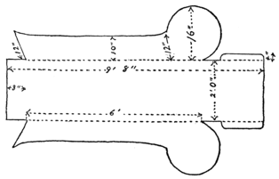
Fig. 200. Bottom Piece of Sleeping Bag.
were just like those of the first sleeping bag, but as there was
no more rubber sheeting in town we had to make the outer
205
bag of enameled cloth, such as is used for carriage curtains.
Out of this cloth Bill cut a piece of the shape shown in Fig.
200 to serve as bottom, sides and ends of the sleeping bag.
The bag was sewed wrong side
out; that is, the piece was laid
with enameled side up, and then the corners were sewed
together after painting the seams with white lead. Then a
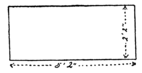
Fig. 201. Top Piece of Sleeping Bag.
top piece was cut out, of the size indicated in Fig. 201. The
edges were hemmed over a piece of rope, which thus formed
a corded edge. Now, with the enameled side of the cover
piece turned inward, its edges were sewed to the edges of the
206
first piece. The bag was now turned inside out, so that the
enameled surface lay on the outside and the seams turned inward.
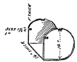
Fig. 202. Headboards.
The corded edge on the cover piece lapped over the
sides, forming a watershed.
It was Bill’s idea to rig up the flap in such a manner that
it would not lie against the face,
so that the sleeper could
have plenty of fresh air,
even in rainy weather. This required the use of two headboards,
of the form shown in Fig. 202. The headboards
were connected at the bottom by a thin board, and to this
framework the sides of the bag were nailed. To the end
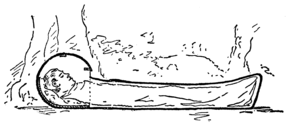
Fig. 204. Sleeping Bag in Use.
flap several cleats were nailed, adapted to fit into notches
cut in the headboards. The cleat at the end of the flap was
207
laid on edge, as shown, and fitted into deep notches in the
headboards just above the edge of the cover piece. This held
the flap securely, preventing it from flying open in a heavy
wind. At the same time the small space between the flap
and the cover piece allowed for an ample supply of fresh air.
When using this sleeping bag, if there was any indication of
a shower, we took care to have the head pointed to windward
so as to prevent entrance of rain through this air space.
The “A” Tent.
In connection with the sleeping bags it may be well to describe here a curious shelter Dutchy and I came across in one of our tramps. It was just about dusk one day when we discovered a temporary camp at which a couple of men were preparing dinner. They informed us that they were naturalists on a two weeks’ outing. At their invitation we joined 208 camp with them. They had a small “A” tent of balloon silk, under which they kept their provisions. The tent had no ridge pole, but was supported instead by a rope stretched between two trees (see Fig. 205).
A Camp Chair.
The camp was also
furnished with an easy
canvas chair, made by
driving a couple of short
posts in the ground for
front legs and a pair of
longer ones for the back. A piece of canvas was hung over
these posts, forming both seat and back. The posts were
driven into the ground on a slant, as illustrated in Fig. 206,
and the canvas was formed
with pockets at the corners
which were hooked over these
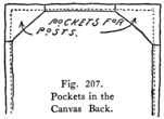
Fig. 207. Pockets in the Canvas Back.
posts. This made a very comfortable
chair, though, of
course, it was fixed to one spot.
When the men moved camp
they would carry with them
only the canvas piece, and at the next stopping place new
posts were chopped and used for legs.
The Camp Bed.
209But what interested us most was the form of bed they had. This, like the chair, consisted of a piece of canvas arranged to be supported on posts cut from the woods in the neighborhood of the camp. The canvas piece was 3 feet wide and 6 feet long, with a wide hem at each side, forming pockets through which poles were passed, as in a stretcher. The ends of the poles were supported on posts driven into the ground. The poles were also propped up at the center, as 210 shown, the pockets being cut away and bound, so as not to permit any wear on the canvas. To prevent the posts from leaning inward under the weight of the sleeper, they were braced apart by cross sticks.
The Camp Bed in a Shower.
As a precaution
against rain, a tall post
was set up at the head
and another at the foot
of the bed, and a rope
was stretched over the
posts with the ends fastened
to stakes driven
into the ground. Over this rope a rubber “poncho”
was laid to keep off the rain. A “poncho,” by the way, is a
blanket of rubber cloth about 4-1/2 feet wide and 6 feet long,
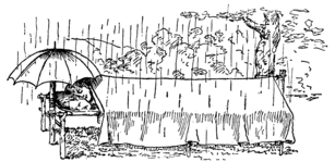
Fig. 211. Camp Bed in the Rain.
211
in the center of which is a slit
through which you can put
your head; then the rubber
cloth falls over you
like a cape, as in
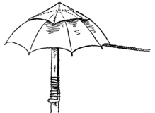
Fig. 212. Umbrella with Fly.
Fig. 210, and makes
a perfect protection against rain. The
ponchos these men had were not quite
long enough to cover the whole bed, so
they fastened umbrellas to the head
posts, as shown in Fig. 212. During a shower in the woods
the rain comes straight down in large drops, caused by the
water collecting on the leaves. To prevent these large drops
from splashing through the umbrellas, they laid pieces of
cloth over the umbrellas, which served, like the fly of a tent,
to check the fall of rain drops.
A Nightmare.
I slept in the mummy case that night and Dutchy in the first sleeping bag. It must have been about midnight when I was awakened by a most unearthly yell. It sent the cold chills running up and down my back. A second scream brought me into action, and I struggled to throw back the head flap, which had become caught. It seemed an age before I could open it and wriggle out of the bag. Dutchy was sitting up in bed with a look of horror on his face, and his whole body was in a tremor of fear. One of the men dashed a glass of water in his face, which brought him back to his senses. It 212 was only a nightmare, we found. Dutchy dreamed he had been injured in a railway accident and had been taken for dead to the morgue. He tried to let them know that he was alive, but couldn’t utter a sound, until finally he burst out with the yells that roused the camp. Then, as he awoke with the horror of the dream still on him, his eyes fell on the two stretcher beds that looked like biers and the black coffin-like sleeping bag. It was not much wonder that Dutchy was frightened. The camp did certainly have a most ghastly appearance in the vague moonlight that filtered through the trees, and it must have been still more gruesome to see the coffin and biers suddenly burst open and the corpses come running toward him. To prevent any further nightmare we set Dutchy’s sleeping bag under the “A” tent, where he would be saved the horror of again waking up in a morgue.
Pack Harness.
In the morning our friends broke camp and started westward.
Dutchy and I watched them packing up their goods
into a couple of very compact bundles, which they strapped to
their backs with a peculiar pack harness. I took careful note
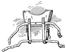
Fig. 213. Pack Harness.
of the way the harness was put together, and when we returned
to the island we made two sets for use on our tramping
expeditions. A canvas yoke was first cut out to the form
shown in Fig. 213. We used two thicknesses of the heaviest
brown canvas we could find, binding the two pieces together
with tape. The yoke was padded with cotton at the shoulders
213
and a strap was
fastened to each
shoulder piece.
These were arranged
to be buckled
to a pair of straps
fastened to the back
of the yoke and
passing under the
arms. Riveted to
these straps were a
pair of straps used for fastening on the pack. The yoke
straps were attached with the rough side against the yoke,
while the pack straps were riveted on with the rough side
uppermost, as indicated in the drawing.
Riveting.
The method of riveting together the leather straps may need a word of explanation. A copper rivet was passed through a hole in the two straps; then the washer was slipped over the projecting end of the rivet. This washer had to be jammed down tight against the leather, and to do this we drilled a hole of the diameter of the rivet in a block of wood, and putting this block over the washer, with the end of the rivet projecting 214 into the hole, we hammered the block until the washer was forced down tight against the leather. Then taking a light tack hammer we battered down the end of the rivet onto the washer. Care was taken to do this hammering very lightly, otherwise the end would have been bent over instead of being flattened.
Only one thing of importance occurred between our Christmas holidays and Eastertide: this was Bill’s invention of the tricycle sailboat or land yacht. We had returned to school with sailing on the brain. Our skate sail served us well enough while there was any ice, but as spring came on we wished we had our canoe with us, or even the old scow to sail on the lakes near the school. Once we seriously considered building a sailboat, but the project was given up, as we had few facilities for such work. But Bill wasn’t easily baffled, and I wasn’t surprised to have him come tearing into the room one day, yelling, “I’ve got it! I’ve got it!” In his hands were two bicycle wheels, which I recognized as belonging to a couple of bicycles we had discarded the year before.
“What are you going to do with them?” I inquired.
“I’m going to make a tricycle sailboat.”
“What?”
“A tricycle sailboat, a land boat, or anything you’ve a mind to call it. I mean a boat just like our ice boat only on bicycle wheels instead of skates. We can sail all over south Jersey on the thing. Come on down and help me build it.”
The Frame of the Yacht.
216I followed him to the shed at the back of the school and found that he had already procured a couple of scantlings for the frame of the boat. The sticks were 2 inches thick and 4 inches wide. The backbone was cut to a length of 10 feet, and a 5-foot link was sawed off for the crosspiece. The two pieces were securely nailed together about 3 feet from the forward end of the backbone. The crosspiece was set on edge, but a notch was cut in it about 1 inch deep to receive the backbone. We might have braced the frame with wooden braces, as in the ice boat, but we thought that this time we would vary the design by using wire bracing instead, thus making the frame much lighter. I asked Bill how he proposed to tighten the wire. Turnbuckles were the thing, but I knew that they were rather expensive.
“Just you leave that to me,” said Bill. “I’ve a scheme that I think will work out all right.”
A Simple Turnbuckle.
At the hardware store
of the town we bought
a pound of No. 16 iron
217
wire, eight large screw eyes and six eye bolts, with nuts and
washers. Both the screw eyes and eye bolts had welded eyes
and the shanks of the eye bolts were 6 inches long. A pair of
screw eyes were now threaded into the backbone at each side
about 18 inches from the end, and at each end of the crosspieces
an eye bolt was fastened. I began to see Bill’s plan.
He was going to draw the wire taut by tightening up the nuts
on the eye bolts. To get the best effect the hole for the eye
bolt had to be drilled in on a slant, so that the bolt would
pull directly in the line of
the wire. To get just
the right angle we ran a
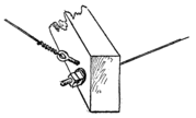
Fig. 217. Stretching the Guy Lines.
cord from the screw eye
on one side to the point
where the bolt was to be
inserted, and traced its
direction on the crosspiece.
The hole for the
eye bolt was now drilled parallel with the mark we had traced.
The same was done at the other end of the crosspiece. A
pair of screw eyes were now screwed into the backbone at
the fore end and a pair of eye bolts were set at a corresponding
angle in the ends of the crosspiece. The crosspiece was
notched at each side so that the nuts and washers on the eye
bolts would have a square seating. Then we stretched
on the wire guy lines, drawing them as tight as possible,
with the eye bolts held in place by a turn or two of the nuts,
after which we screwed up the nuts as far as we could, thus
218
drawing up the wire until it was very taut. This done the
second nut was threaded onto each bolt against the first so
as to lock it in place and prevent it from jarring loose.
Stepping the Mast.
Our next task was to step the mast. We found in the shed an old flagstaff 15 feet long and 3 inches in diameter. The lower end of this, for about a foot, we whittled down to a diameter of 2 inches, and drove it into a hole in the backbone 12 inches from the forward end. The mast was stayed by a wire stretched from the head to an eye bolt at the fore end of the backbone. The end of the mast which projected below the backbone was stayed with wire running forward to an eye bolt and aft to a screw eye on the backbone, and also with a pair of wires running to screw eyes threaded into the crosspiece near the ends. We couldn’t very well use eye bolts on these wires except at the fore end, but we stretched the wires as tight as possible before the screw eyes were screwed all the way in, and then, as we turned the screw eyes, the wire was wound up on them and drawn fairly taut. Fig. 219 shows a side view of the frame, and wires marked 1 and 2 are the same as illustrated in Fig. 218, which is a top or plan view of the frame.
Mounting the Frame on Bicycle Wheels.
219We were now ready to mount the frame on the bicycle wheels. We used only the front wheels of the bicycles with the forks in which they were journaled. The shanks at the top of the forks were firmly driven into holes in the crosspiece near the ends. For the steering wheel Bill took the front fork and wheel of his new bicycle, letting the shank into a hole at the stern end of the backbone.
The Tiller.
For a tiller we used a piece of an old rake handle. A
small hole was first drilled into the handle and the end of the
stick was then split through the hole, permitting the projecting
shank of the fork to be driven tightly into the hole.
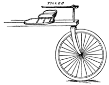
Fig. 221. The Seat.
The split wood was now tightly closed onto the shank by
means of a bolt (see Fig. 220). In the rubbish heap we
found an old chair. The legs were sawed off and the seat
was then firmly nailed to the backbone. The back of the
chair was cut down so that it just cleared the tiller.
A “Leg-of-Mutton” Sail.
220Everything was now
completed but the sail.
This was a triangular or
“leg-of-mutton” affair,
of the dimensions
given in Fig.
222. It was
made of light canvas, 30 inches
wide, of which we bought 14 yards.
Out of this we took one strip 18
feet long, one 13 feet, one 8 feet,
and one 3 feet long. We had no
sewing machine, and therefore had
to sew the strips together
by hand. The selvedge edges of the strips
were lapped over each other about an inch
and then they were sewed together sailor
fashion, that is, each edge was
hemmed down, as shown in Fig.
223. The strips were sewed together
so that at the foot each
projected at least 21 inches
below the next shorter
one. This done, the sail
was cut to the dimensions
given, allowing 1-1/2
221
inches all around for the hem. The hem was turned over
a light rope, forming a strong corded edge. At the clew,
tack and head loops were formed in the rope which projected
from the canvas, and at intervals
along the foot the canvas was cut
away, exposing the rope so that the sail
could be laced to the boom, as illustrated.
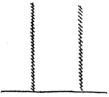
Fig. 223. The Sailor’s Stitch.
The boom was a pole 11 feet long attached
to the mast by means of a screw
hook threaded into the end of the boom
and hooked into a screw eye on the
mast, after which the screw hook was
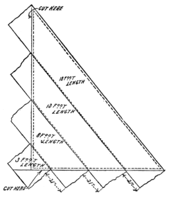
Fig. 224. Laying Out the Sail.
hammered so it would close over the
screw eye to keep it from slipping off.
The sail was raised by a halyard passing
over a block at the top of the
mast. The sheet was fastened
near the end of the boom,
passed through a block on
the backbone, back of the
tiller, and through
another block on
the boom, and
was led to a
cleat within
easy reach of
the chair seat.
A Sail through the Country.
222Our land yacht proved to be quite a successful craft in the flat country around the school. Of course, we could not sail everywhere; a country road is too narrow for any tacking when it comes to sailing against the wind. We hadn’t thought of that when we made our trial trip. A strong east wind was blowing and so we ventured forth on a road that led due west from our school. Off we sped before the wind for two miles, until we came to a sharp turn in the road. Then we began to think of turning homeward. But this was a very different proposition. The wind was dead against us and to try to tack from side to side of the road was useless, 223 because we would hardly get under way on one tack before we had to swing around on the other tack, losing all our momentum. It ended up by our lowering sail and ignominiously trundling the yacht back to school. After that we carefully selected our course, and never sailed away from home before the wind unless we knew of a roundabout way that would lead us back to port on a couple of reaches (long tacks).
Just before Easter that year Bill’s Aunt Dorothy invited him to spend Eastertide with her and bring along his roommate. I accepted the invitation with alacrity. Bill had once spent a whole summer at his aunt’s home, and when we arrived there he had many old haunts to visit. We spent the first day rambling through the woods, in the hills and back of the house.
Bill’s Cave.
He introduced me to a cave which he believed was known to only two other boys, both of whom had since moved to New York city. The mouth of the cave was almost closed by a large boulder that had lodged in front of it. We had to climb to the top of this rock, and then letting ourselves down with a rope we slid down the sloping rear face of the boulder into a crevice in the rocks. Then after squirming under a ledge we emerged into a large chamber, which appeared to be as dark as night after our sudden entrance from the outer light.
225Bill lighted a candle which projected from a chink in the wall. By its light I saw that there was a pool in the center of the cave fed from a spring at one point. From the pool the water trickled off into a tiny stream to the mouth of the cave, where it was lost in a crack in the rocks. The water was ice cold and clear as crystal. Around the pool were several chairs and a table made by Bill and his two friends. That was evidently where Bill had gotten his idea of a subterranean club.
The Barrel Stave Hammock.
226Hanging between a couple of projecting rocks was a hammock
made of barrel staves. The hammock was a very
simple affair, made by drilling a 1-inch hole in each end of
each barrel stave. The staves were then connected by two
ropes on each side, woven alternately in and out through
these holes, that is, one rope would be passed down through
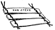
Fig. 228. Tying the Staves Together.
one stave, up through the next,
down through the third, etc.,
and through the same holes
another rope would be
threaded in and out but
in the opposite direction.
The end staves of the
hammock were provided with double holes, as shown in Fig.
228, so as to make them lie flat, then the ropes were threaded
through them.
The Barrel Armchair.
227Aside from the hammock and
the rustic furniture there was a
fine armchair, made from a
barrel that had been sawed off, as
in Fig. 229, to form the arms and
back. The barrel was raised
from the ground by setting it on
a couple of boards arranged in
the form of a V. Then a caster
was fastened to the point of the
V and another at each end, making
a three-legged chair of it.
The chair was upholstered with ticking stuffed with straw.
First a piece of ticking large enough for the back was laid
on the ground and covered over with an even layer of straw.
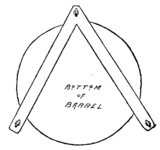
Fig. 230. Casters on the Chair.
Over the straw a second piece of ticking
was laid, making what Bill
called a “straw sandwich.”
This was nailed to the chair
back along the edge and at the
bottom, drawing the cloth as
taut as possible. To make
a better finish for the chair,
the ticking was covered with
dark red denim. Then strips
228
of braid were laid on the chair back,
crossing each other like a lattice. At
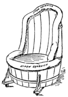
Fig. 231. Tacking on the Straw Sandwiches.
the crossing points of the braid brass-headed
tacks were nailed right
through the sandwich into the
wood, producing the padded
upholstered effect. Next a long,
thin sandwich was made to run
along the edge of the back, and
another one to run around the
chair just below the seat, also a
couple of small sandwiches to
cover the legs and the brackets
leading to them. These were all covered with denim before
being tacked to the chair and then they were bound with
tape at intervals to produce
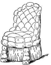
Fig. 232. The Barrel Armchair.
the padded effect. The
rest of the woodwork was
covered with denim, and a
neat ruffle made by Aunt
Dorothy hung about the
bottom of the chair. A
thick, round sandwich was
now made to cover the seat
board. This was also given
a padded effect by binding
it with tape. The seat
board was not nailed to the
229
chair, but rested on four cleats nailed to the barrel on the
inside. When the seat was lifted out it uncovered a shallow
chest in which various things could be stored.
The Summer Toboggan.
Bill informed me that he and his two chums used to spend hot summer afternoons in this cool place whittling out various ornaments and making furniture for the cave. In one corner were a number of home-made amusement devices, one of which struck me as rather odd. It consisted of a pair of large barrel staves, hollow side up and connected with two short boards, as in Fig. 233. Bill said it was a summer toboggan, to be used on grass instead of snow. I had never heard of such an affair, and, of course, had to have a demonstration. Bill went to the top of the hill and from there coasted down the grassy slope in fine style.
Tailless Kites.
“There’s a better place over on the other side of the hill,” he said, and led the way to his favorite coasting spot. 230 But here our attention was diverted from coasting by the curious sight of a full-grown man flying a kite. We found out afterward that he was a Professor Keeler, who had made a great scientific study of kites. Professor Keeler was very affable, and we soon got acquainted with him. His kite was way up in the air, almost out of sight, and was pulling like everything. Neither Bill nor I could hold it long. But the most remarkable part of it all to me was the fact that the kite had no tail. I had heard of tailless kites made like a box, but this one appeared to be very much like the kites I had made in my younger days, and I well knew the importance of a long tail to keep such a kite steady. We asked the professor about it, and were informed that this kite was of the Malay type, which is so designed that the cloth bellies out into pockets on each side of the central stick or backbone, 231 and these pockets balance the kite while the backbone acts as a rudder.
Finding that we were interested in the subject he gave us full instructions for making kites from 5 to 8 feet long, and these I jotted down for future use. In a 5-foot kite he said the stick should be 3/8 inch thick and 1/2 inch wide, in a 6-foot kite 7/16 inch thick and 9/16 inch wide, in a 7-foot kite 5/8 inch thick and 3/4 inch wide, and in an 8-foot kite 3/4 inch thick and 1 inch wide. On the following summer we built a 5-footer and also an 8-footer.
A Five-foot Malay Kite.
For the 5-foot kite we used two sticks of hickory 3/8 of an
inch wide, 1/2 an inch thick, and each 5 feet long. According
to directions, one stick was laid across the other at a point two-elevenths
of its length from the top. Two-elevenths of 5 feet
is a little less than 11 inches, and so we fastened on the
cross stick 11 inches from the upper end of the backbone.
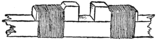
Fig. 235. Tying on the Cleats.
The sticks were not nailed together, because this would have
weakened the frame just at the point where it was under
the greatest strain. Instead we followed the professor’s
directions and tied cleats to each stick, as shown in Fig. 235,
so as to form sockets. Then the sticks were laid across
each other, each stick fitting into the socket of the other, just
like a mortised joint. A coat of shellac on the bottom of
each cleat glued it temporarily to the stick, after which it
was very tightly bound with fine cord. The stick and cleats
232
were now thoroughly shellaced. The end of each stick was
tapered off to receive a brass ferrule of the kind used on

Fig. 236. Hook on the Vertical Stick.
chisel handles. They can be bought at any hardware store.
At the end of the backbone
we fastened hooks made of
brass, bent to the form
shown in Fig. 236. The
cross sticks were also provided with hooks, but these were
double, as shown in Fig. 237, so that a hook lay on both
the front and the rear side of the frame.
The frame was covered with a kind of cloth called “percaline.”
The cloth was hemmed along

Fig. 237. Double Hook.
each edge over heavy picture wire, and at
each corner the wire was twisted around
a small solid ring of brass. The rings
were now slipped over the hooks on the
frame and then the cross stick was bowed
back by fastening a wire to the rear hooks
and drawing it taut. Professor
Keeler told us to tighten this
bowstring until the distance from the
wire to the cross stick at the center was
equal to one-tenth of the length of the
stick. As our sticks were each 5 feet long
we tightened the wire until the cross
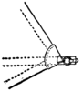
Fig. 238. Connection at Corner.
stick bowed out 6 inches, as in Fig. 239.
The belly band of the kite was fastened at one end to the
lower end of the backbone and at the upper end to a wire
233
hook at the juncture of the two sticks. The hook was
fastened to the cross stick by flattening the ends and running
them under the cord used for binding on the cleats (see Fig.
240). A buttonhole was made in the cloth covering to let
this hook project through. The belly band was just long
enough, so that it could be stretched over to one end of the
cross stick, as in Fig. 241, and at this point, that is, 30 inches
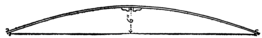
Fig. 239. Bending the Cross Stick.
from the upper end of the belly band, a brass ring was made
fast, to which the main kite string was tied. The kite possessed
the advantage that it could be quickly taken apart
and folded into a small space.
An Eight-foot Malay Kite.
Our 8-foot kite was made in the same way only the sticks were 3/4 inch thick, 1 inch wide and 8 feet long. The cross stick was fastened 17-1/2 inches (two-elevenths of 8 feet) from the top of the backbone and it was bowed back 9-1/2 inches (one-tenth of 8 feet). The wire in the hem of the covering was a double thickness of the heaviest picture wire obtainable.
The Elastic Belly Band.
235An important change was made in the belly band of the kite. The lower strand was made elastic by tying it fast to a number of heavy rubber bands, as in Fig. 242. When flying the kite, if a sudden, strong puff of wind struck it, the elastic belly band would give, tilting up the lower end of the kite so that the wind passed under; but as soon as the gust had passed the rubber bands would draw the lower end of the kite back against the wind. The elastic belly band had the effect of making the kite rise almost vertically. Sometimes it would even sail square overhead. The 8-foot kite was a very powerful one. To hold it we had to use a very strong cord, the kind used by upholsterers for tying down the springs in a chair or a sofa.
Putting the Kites to Work.
Bill tested the strength of the kite once by hooking a spring scale to the kite string. The scale was made to register weights up to 25 pounds. But our kite yanked the pointer immediately past the 25-pound mark as far as it would go. We judged from this that the kite would lift at least 40 pounds. Such a pull as this it seemed a pity to waste, but how to utilize the power was a problem until one day, when the kite was soaring up on a south wind, Dutchy suggested that we tie it to one of the canoes and go sailing up-stream. 236 We tried the trick at once, but it didn’t work very well, because the canoe was too light. The kite would drop unless there was a heavy pull on the string. We had better success with the scow, however, which provided a sufficient drag on the kite, and with the two kites to pull us we sailed a long ways up-stream, drifting down with the current when we had gone as far as we cared to.
The Diamond Box Kite.
Professor Keeler also gave us instructions for making a diamond-shaped box kite, and though we never built one, it may not be amiss to publish his instructions here. I quote from the chronicles of the S. S. I. E. E. of W. C. I.:
“Materials: Four sticks, 1/4 inch thick by 5/8 inch wide by
44 inches long, for the corner sticks. Two sticks, 1/4 inch
thick by 5/8 inch wide by 15 inches long, for the short
spreaders. Two sticks, 1/2 inch square by about
237
38 inches long, for the long spreaders. Two strips of cloth
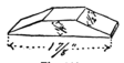
Fig. 244. Cleat for Spreader.
81 inches long, hemmed at each edge to a width of 13 inches.
Whittle out twelve cleats to the form
shown in Fig. 244. At the ends of
the 15-inch spreaders nail cleats on
each side with long wire brads, so as
to form forks, as shown in Fig.
245, in which two of the corner sticks are held. The
short spreaders are fastened to the corner sticks, 7 inches
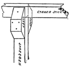
Fig. 245. Corner Stick and Spreader.
from the ends, with brads
driven through the cleats,
making the frame (as in Fig.
246). To prevent the frame
from skewing off sidewise it
should be braced with wire running diagonally
across from one corner stick to
the other. Ordinary soft stovepipe wire
will do. Care must be taken to have the
spreaders meet the corner sticks squarely
or at right angles. Now take one of the cloth strips and sew
its ends together to form a band. The end should be lapped
about an inch and fastened with the sailor stitch (see Fig.
223). The same
should be done to
the other cross strip,
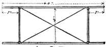
Fig. 246. The Narrow Frame.
and then each band
should be marked
off with pencil lines
238
at four points, all equidistant from
each other. The two bands may
now be tacked to the two ends of
the frame with opposite pencil lines
over the edges of the corner sticks,
as in Fig. 247. The
two remaining corner
sticks are then
nailed to the
bands at the two
other pencil lines.
These corner
sticks will now be braced
apart by the long spreaders,
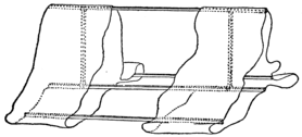
Fig. 247. Tacking on the Cloth.
which are notched to
the right length to stretch
the cloth taut. A cleat is
nailed over each notch, as shown in Fig. 248, forming
forks to hold the corner pieces. The long spreaders are
now forced down until they meet the short spreaders, to
239
which they are tied with waxed string. The long spreaders
may be nailed to the corner sticks by driving brads right
through the cloth into the cleats and the sticks. The belly
band may be fastened to any one of the corner sticks at the
spreaders, and from the points where it is tied it should
measure about 45 inches in length. The point where the
main string should be attached to the belly band may be best
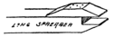
Fig. 248. Forked End of Long Spreader.
determined by experiment.”
Summer found us again on Willow Clump Island with heads full of new ideas. Bill had come across an old copy of Ewbanks’ “Hydraulics” in the school library. It was a book describing machines of the ancients–principally devices for raising water. Rather dry reading, I thought, even though it was a wet subject; but Bill seemed to find it absorbingly interesting. I came in late one afternoon, after a glorious game of baseball, only to find Bill poring over the yellowed leaves of the “Hydraulics” as fascinated as most fellows would be over a detective story. It exasperated me to note that he thought more of this old book than he did of our baseball team.
“Bill,” I exclaimed, “what’s got into you? I can’t for the life of me see what is so entertaining in that prehistoric book.”
“Oh, go way. Don’t bother me,” was the surly reply.
But I wouldn’t be put off that way. Quickly I snatched the book from his grasp and threw it out the window.
“Now, sir,” I cried, “maybe you will kindly explain to me why you persist in studying that old volume, to the neglect of our baseball team.”
241“Don’t get so excited, old chap,” he replied. “That book is all right. I’m studying up some new schemes for next year’s expedition to Willow Clump Island. Why, there are lots of things in that old book that we can make.” And he proceeded to unfold his plans, sketching out some curious designs of water wheels and pumps.
By the time school closed for the summer Bill had thoroughly digested that volume, and was ready to reconstruct many of the ancient machines.
The Water Wheel.
Our first work on reaching the island was to erect a water wheel, or “noria,” as it was called in the book, in front of the camp. It had been a great nuisance to keep our filter barrel full. Every few days we would have to form a bucket brigade, passing pails of water up the line until the barrel was filled. Now Bill proposed to do away with all this bother and let the river do the work for us.
Surveying for the Water Wheel.
We first determined the height of the upper filter barrel above the level of the river. This was done with our surveying instrument, which was set level with the top of the barrel. We sighted with the instrument to a long pole that was held upright at the edge of the water. The pole had been marked off into feet with white chalk marks, and on sighting through the sight holes we found that the hairs 242 came in line with the eleventh chalk mark. The top of the filter was, therefore, 11 feet above the level of the river. Bill figured that it would be necessary to construct a wheel about 15 feet in diameter in order to raise the water to the proper height.
Towers for the Water Wheel.
First 243 we built the towers to support the wheel. One tower was 16 feet high and the other only 10 feet. The large tower was made something like a very tall and narrow saw-horse. Two stout poles 17 feet long were flattened at their upper ends and nailed together, with the ends projecting about a foot, as shown in Fig. 251. At the bottom these poles were spaced 8 feet apart by a cross bar, and about 9-1/2 feet from the bottom a pair of boards were nailed to opposite sides of the pole to serve as supports for the axle of the water wheel. Another pair of 17-foot poles was now similarly fastened together and then the two pairs were spaced about 12 feet apart and connected at the top and bottom with 244 boards.
At the top two smooth
boards were used and
these were nailed to
the inner sides of the
projecting ends,
which were tapered
off. In this manner
a V-shaped
trough was
formed. The
boards were
firmly nailed together
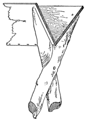
Fig. 253. V-shaped Trough.
at their meeting edges so as to prevent them from
warping apart. A diagonal brace at each corner made the
wedge-shaped tower very substantial. A number of cleats
nailed to one of the poles
provided a ladder by which
we could mount to the top
of the tower. The shorter
tower was a three-legged
affair, made of three
12-foot poles. At first two
of these were flattened and nailed
together at their upper ends, and
they were braced at the top and
bottom. The third leg was then
nailed in place and braced by cross
bars connecting it with the other
two poles.
The Wheel.
245We were now ready to
make the wheel. From
Lumberville four 1/2-inch
boards, each 3 inches wide
and 15 feet long, were procured;
also a bar of iron 3/4
of an inch in diameter and
2 feet long. At the center
of one of the boards a block
of wood 4 inches long and
4 inches in diameter was
nailed on for a hub. A
3/4-inch hole was
now drilled through
this hub and the
board. Holes were also drilled into the
other boards at their centers. Then they
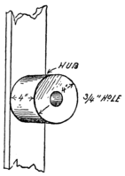
Fig. 255. The Hub.
were all strung onto the bar and
spaced like spokes at equal angles
apart. Bill had figured it out
some way that the ends of the
boards should be just about 5 feet 10-1/2 inches
apart. When the boards were all arranged we
nailed them together at the center, and connected
the ends with narrow tie boards, as
indicated in Fig. 256.
The Buckets.
246Eight large tomato cans were now procured and fastened to the spokes at the ends on the inner side, that is, the side the hub was nailed to. We couldn’t very well nail on the cans, so we punched two holes in the side of each can and then secured them to the spokes by passing bolts through these holes and the boards.
The Paddles.
Then we cut sixteen paddles of the form shown in Fig. 257. Eight of these were 12 inches long, and the rest measured 18 inches. A slot 3 inches deep was cut in each paddle of just the right width to slip over the tie boards. The shorter paddles were fastened on just back of the spokes, and the rest were secured half-way between each spoke. The paddles were braced by stretching a wire from one to another all the way around the wheel.
The Receiving Trough.
247Our next task was to nail
the receiving trough in
place on the higher
tower. We set up
the towers on land
and mounted the
wheel between them
with the axle resting
in the crotch of the
short tower and in a
deep notch cut in the
cross boards of the
larger one. The cans on the
wheel faced the larger tower,
but the hub at the center and
a block nailed to the larger
tower spaced the wheel far
enough out so that the cans did not strike the tower as they
revolved. We carefully measured the distance between the
spokes and the larger tower, and
then built a square trough of a
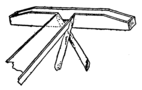
Fig 259. The Receiving Trough.
size to just fit into this space.
This trough was nailed across
the end of the V-shaped trough
on top of the tower, but a notch
was cut in the side so that the
248
water would pour from the square or receiving trough into
this V-shaped one. The square trough was about 8 feet
long and its sides were 12 inches high; but at the ends we
had to cut them down to a height of but 6 inches, so as to
permit the cans to pass without hitting them.
Setting Up the Towers.
Our filter was located nearly 20 feet from the end of the river, and in order to get a good current of water to revolve our wheel we had to place it about 15 feet from shore. This necessitated building a trough line 35 feet long. Ten feet of this line were already provided in the top of the tall tower. This tower was now set up in place with the legs firmly wedged into holes excavated in the bottom of the river. The legs on the shore side were sunk a little deeper, so as to tilt the trough slightly shoreward. The outer end of the trough was about 12 feet above the level of the water. We needed but one more tower to support the remainder of the trough line. This tower was built like the first one, but was much shorter, as it was erected on land and the level of the trough at the top had to be 5 or 6 inches lower so as to make the water flow. We connected the towers by another V-shaped trough section. This we nailed to the under side of the first trough and to the inside of the second trough. The latter was then in the same way connected by a trough section with the upper filter barrel. We now rigged up our shorter tower about a foot from the taller one, wedging in 249 the legs so that the top came level with the slotted boards of the other tower.
Mounting the Water Wheel.
Then came the task of mounting our wheel in place. We were working in a pretty strong current and found it no easy matter. In the first place, the wheel was floated down to the towers, but there it got jammed and we couldn’t lift it up. One of the paddles was broken and a bucket wrenched off before we could disentangle the wheel from the towers, and then the wheel was carried quite a distance down-stream before we could drag it in to shore.
Our next attempt was more successful. This time we anchored the wheel so that it just cleared the towers, then fastening a couple of long guy ropes to it, we raised the wheel on edge, while a boy stood on each side holding the ropes to keep the wheel steady. The anchor rope was now slowly paid out and the wheel was rolled in between the towers. This done, the wheel was lifted up and the axle rod was pushed in, with the ends of the rod resting in slots of the boards on the tall tower and in the crotch on the shorter one. To prevent the axle rod from working endwise out of its bearings, we nailed pieces of wood across the crotch and the slots against the ends of the rod. Then we cast off the anchor rope and our wheel started work, the cans dipping up the water as they were carried around by the wheel and pouring it out of the top into the receiving trough, from which the water flowed down into the filter barrel.
Cooling the Filter Barrel.
250The trough line was very leaky and a great deal of water splashed out of the buckets. But for all that, within a few moments our barrel was full and overflowing. We hadn’t figured on its filling so rapidly, but we soon found a way of utilizing the surplus water. It was led to a half-barrel in which we washed our dishes, and from there it flowed through a ditch back to the river. The water for the wash barrel was taken from the top of the upper filter barrel. But we let the lower filter barrel flow over so that it would be kept wet on the outside. Our filter was fortunately placed at a point where a good breeze struck it, and we 251 shoveled away the earth that had been piled around it so that the wind playing on the wet barrel evaporated the moisture, making the water inside very cool.
The Canvas Bucket.
This same trick was used for cooling our drinking water
whenever we went off on an expedition away from camp.
We had a heavy canvas bucket, the kind used on ships. We
would fill this bucket with water and then hang it up in the
wind. The water seeping out of the pores of the bucket
would be evaporated by the wind, and this would, in a few
moments, make the water inside delightfully cool. Such
buckets may be bought for $1.50 to $2.00 apiece, but ours
was a home-made affair, and made somewhat differently from
the store kind. The canvas used was the heaviest we could
find. A piece 9 inches in diameter was cut out for the
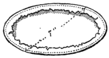
Fig. 261. Bottom of Bucket.
bottom. A ring 7 inches in diameter, made of heavy brass
wire, was laid on the canvas, and the cloth was turned over
it and sewed down the inside of the ring. For the sides of
the bucket we cut a piece 14 inches wide and 23 inches long.
The upper edge was strengthened by a piece of light rope
held in place by hemming the cloth over it. The lower edge
was now sewed to the bottom,
just inside the wire ring and
then the ends of the piece were
joined, completing the sides
of the bucket. The bail of the
bucket was formed of a
252
piece of rope fastened to the roped upper edge of the
bucket.
But to return to the current wheel; the day after it was completed, when I went over to Lumberville for the mail, I was met by old Jim Halliday, who wanted to know what sort of a rig we had out on the river. I told him, and after a dint of much persuasion, induced him to take a ride back in the scow with me. He had never visited our camp and hadn’t realized how handy we were with the tools, because, with the exception of the current wheel, all our work had been done on the opposite side of the island. We made him a guest of honor, showing him over the whole place. The bridges struck him as remarkably clever, but what pleased him most was our current wheel.
“I swan,” he said. “Ef that ain’t jest the thing I have been awantin’ for the past twenty year. What’ll ye sell me the hull plant fer, boys?”
Mr. Halliday’s Water Wheel.
We thought he was fooling at first, but when he had
assured us that he was in earnest, Bill told him that we
needed our own plant, but we could build him a similar
and even better current wheel for any amount he thought
253
it was worth to him. The figure settled on was six dollars
(a dollar apiece) for our work, Mr. Halliday paying for
the material. It was not a
large sum, but it seemed
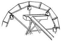
Fig. 263. Mr. Halliday’s Water Wheel.
a lot to us, and considering
the scarcity of
money in that region
it was pretty generous
pay. We built Mr.
Halliday’s current
wheel just like our
own, except that the paddles were much broader, and instead
of using cans for the buckets Mr. Halliday supplied us with
small dinner pails. The method of fastening on the pails
is shown in Fig. 263. A stick was nailed across the end of
each spoke and the bail of the pail was held by a screw eye
threaded into this stick. The pails would hang straight,
holding all the water without spilling a drop until the receiving
trough was reached. This trough was fastened high
enough to strike the bottom of the pails as they went by,
tipping them over and emptying them of their contents.
From the trough the water ran directly into a large cider
barrel and from here was carried through a pipe to Mr.
Halliday’s barn. A stopcock was here provided so that
he could turn the water on or off, as he desired. The use of
pails was a great improvement on tin can buckets. Fully
three times as much water was poured into the receiving
trough, because not a drop was spilled out on the way up.
Immediately after fitting out Jim Halliday with his water wheel we set to work on our log cabin. As a model we had a photograph of a log hut which Uncle Ed had sent us. As the cabin was designed particularly for use in winter time, we decided that it should be located where it would be sheltered from the northern winds and would be exposed to the sun. The ideal spot seemed to be on the southern shore of Kite Island, which was backed by a thick grove of trees but gave an unobstructed view in front for a distance of about four miles down-stream.
Foundation of Log Cabin.
First we staked out the plan of the house. It was to be 12 feet long by 10 feet wide, so we leveled off a space of this area, and at the corners, where the greatest weight of the building would come, large rocks were embedded in the ground.
A Logging Expedition.
255The logs for the house were cut from a tract of wooded land about five miles up the river, belonging to Mr. Schreiner. To be sure we could have cut the timber from our own island, but when Reddy had said something to his father about our building a log cabin, Mr. Schreiner had warned us not to cut down any of the trees without the owner’s permission. All we could learn about the owner was that his name was Smith, and that he lived somewhere in New York city. It seemed unlikely that he would ever have anything to say about our cutting down a few trees, but rather than run any risk Mr. Schreiner advised us to make use of his woods for any timber we might need. Accordingly we started out early one morning on a logging expedition. We had no apparatus for handling any logs more than 6 or 8 inches in diameter, and Bill reckoned it out that we would have to have about fifty logs of this size for the sides of the building alone. This did not mean that fifty trees had to be chopped down, because we could usually cut two logs from a single tree. As the logs would have to overlap about a foot at each corner, we had to cut the longer ones to a length of 14 feet and the others to a length of 12 feet. Aside from these we had to have several 16-foot logs for the roof. Only the straightest logs were chosen, and while Bill and Reddy wielded the axes the rest of us hacked off the small branches with hatchets and hauled the sticks down the river. Here we tied them together to make a raft.
The Log Raft.
256This was done by running a pair of ropes alternately over
and under the logs at each end (see Fig. 264). About
fifteen were thus fastened together, and then as an extra precaution
a log was laid across each end of the raft and tied
fast. As soon as we had cut enough timber for our first
raft, we all ceased
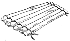
Fig. 264. Tying the Logs Together.
work, to take a ride
down the river on
the logs. Two of us,
armed with poles,
were to do the steering.
There was one
spot in the river of which
we were rather apprehensive.
That was a bit of shallow, swift water three miles
from camp. A line of rocks jutted up from the river, forming
a natural dam which was broken only at the eastern end.
The water swirled madly through this opening, and veering
off a huge rock which lay directly in front of the gap turned
sharply westward. As we neared this dam the river became
deeper and deeper, until finally we could no longer reach
bottom with the poles, and could not properly steer the boat.
For some time we drifted helplessly round and round in the
still water above the dam. Then suddenly the current
caught us and we swept like a shot for the opening. The
257
gap was quite wide, and had we only thought to provide
ourselves with oars we could have steered the raft clear of
the rocks below, but we were entirely at the mercy of the
current, and with a terrific crash we were hurled head on
against the boulder.
Just what happened then I can not say. When I undertook to record the incident in the chronicles of the S. S. I. E. E. of W. C. I., I found there were five entirely different versions of the affair besides my own. I knew that immediately after the shock I found myself struggling in the water just below the rock over which I must have been slung by the force of the impact. Dutchy declared up and down that he had sailed fifty feet in the air astride of a log. Bill had been almost stunned by a blow on the head and was clinging desperately to a jagged projection of the rock. The ropes that had held the raft together had parted, scattering the logs in all directions, and I could see the rest of the crew hanging on to them for dear life.
Shouting to Bill to let go his hold on the rock. I swam over and caught him as he drifted down, then I helped him ashore. Leaving Bill to recuperate I rushed down the bank, shouting to the others to paddle the logs over toward shore. Then I plunged in, and pulling myself up on the nearest log, paddled shoreward as we had done on the planks when shooting the rapids. In this way one by one we corralled the logs, and after tying them together again resumed our voyage down the river. We now had no swift water to fear and were able to guide the raft successfully down to Lake Placid. 258 But here we moored it, not venturing to take it past the mill-race until we had gotten the oars from the scow and nailed on oar locks at each side and the rear, so that we could properly row and steer the raft safely to Kite Island.
The Sail-Rigged Raft.
When we went up the river again we carried the oars with us, also the sail and mast belonging to our ice boat, as there was a good breeze blowing down-stream. Our second trip was more successful. The mast was stepped in a small but solid box nailed to the logs. In the top of this box a hole was cut for the mast to fit into and then the mast was braced with guy lines. We came down the river in fine style, steering straight for the opening in the dam, and just as we were about to shoot through Reddy and I plied the oars for all we were worth on the port (left) side so as to swing the raft around past the boulder. However, 259 we didn’t escape entirely without accident, for the raft rode up on a submerged ledge, dipping the starboard side clear under water and nearly tipping us over. But in a moment the raft had righted itself and we had smooth sailing for the rest of the way.
Building the Log Cabin.
Our third expedition completed the number of logs we
required for the log cabin. Two large 12-foot logs were
chosen for the foundation logs at the front and rear of the
building. The logs were flattened along the bottom so that
they would have a firmer bearing on the ground, and particularly
on the corners, where they rested on foundation stones.
Each log was now notched about a foot from the ends. The
notches were 8 inches long and about 2 inches deep. Care
was taken to place those on one log squarely opposite the
notches on the other. A pair of 14-foot logs were now laid
across the foundation logs and rolled along them until another
half-turn would have dropped them into the notches
(shown in Fig. 266). Then notches were cut in the 14-foot
logs to correspond, so that when the final half-turn was
given one notch would fit over
the other, making a mortise
joint (Fig. 267).
When the side
logs were in
position
260
notches were cut in their upper surface to receive a pair of
12-foot logs which were rolled onto them, notched and
dropped into place. Then another pair of side logs were
laid on, and so the work progressed.
The notches in
each log were cut to
a depth equal
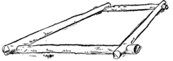
Fig. 267. Foundation Logs Fitted Together.
to one-quarter
the diameter of
the log; that
is, if the log was 8 inches in diameter the notch was made 2
inches deep, and if 6 inches in diameter it was cut to a depth
of 1-1/2 inches. When the logs were laid in place no space
intervened between them, as will be clearly understood by
reference to Fig. 268.
We found, after a few logs had been set in place, that our
cabin was growing faster at one end than at the other. The
trouble was that our logs were not of uniform diameter
throughout, and we had been laying the butt ends, which
were larger, all at
one end of the
building. So we
had to take down
the logs and relay
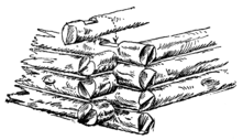
Fig. 268. A Corner of the Log Wall.
them with the butt
end of the front
foundation log at
one end and that of
261
the rear foundation log at the other. Then the cross logs
were laid on with their butt ends on the small ends of the
foundation logs. The next end logs were laid with their
small ends on the butt ends of the cross logs, and so on, taking
care never to lay the butt end of one log across the butt end
of another. In this way the walls were built up evenly to a
height of 3 feet.
We had planned to make a large open fireplace in the cabin, and this necessitated cutting an opening in the rear wall. But we did not want to cut the opening until the wall was built up to its full height lest it might buckle while the remainder of the logs were being placed in position. So we merely cut a piece out of the top log to make room for a saw when we were ready to cut the complete opening. As our fireplace was to be 5 feet in width, a 5-foot piece was cut out of the center of the log. Then the ends were supported by cleats nailed on each side, as shown in Fig. 269. This done the building was continued as before, but as the walls grew we found it more and more difficult to raise the logs to 262 position. We could not lift them directly to the top of the wall, but had to roll them up on “skids”; that is, on a pair of 14-foot logs which were laid against the top of the wall. When the walls had reached a height of about 5 feet above the foundation logs, a length 4 feet 9 inches long was cut out of the top log to allow space for sawing out the front door and window, and also a 30-inch piece was cut out for the side window. Cleats temporarily held the sawed ends of the logs, while the walls were carried on up to a height of a little over 6 feet from the foundation logs.
The Roof of the Log Cabin.
Then we started laying the roof. A 16-foot log was now notched in place at each side, with its forward end projecting about 3 feet over the front of the cabin to form a shelter in front of the building. A pair of 12-foot logs were then laid in position. The next pair of 16-foot logs were laid about 20 inches in from the sides, and after a pair of the cross logs had been set in place a third pair of logs were laid about 40 inches from the sides. Finally, a single 16-foot log was set in place at the center, to serve as the ridge beam of the roof. The roof logs were all carefully tested to see if they were sound before we laid them in place, because we did not want to run any risk of the roof falling in, particularly in the 263 winter time, when it would be heavily covered with snow. A chalk line was drawn from the ridge beam to the lower roof beam, and the cross logs were sawed off along this line, as indicated in Fig. 271. Several slabs were now procured and laid across the roof beams to serve as rafters. These rafters projected about 18 inches beyond the side walls of the cabin, so as to support the eaves. Over the rafters we laid a roofing of slabs, starting with the bottom and lapping them, as we had done on our tree house.
The Door and Window Frames.
We were now ready to cut out and frame the doors and window openings. The front window of the cabin was to be 264 close beside the door, so we merely widened the door opening at the top to include the window opening as well (see Figs. 271 and 272). The door was made 2-1/2 feet wide, and was cut down to the foundation logs. The window opening was cut to a depth of 24 inches. Before sawing out the opening we wedged pieces of wood between the logs along the line we were to follow with the saw, so as to keep them in place. After the opening had been made a couple of stout boards were nailed to the sawed ends of the logs at each side, to hold them securely in place and make a suitable framing for the door. The cleats were then removed. The foundation log and the one at the top of the opening were flattened, to serve as the sill and lintel of the door. Between the door and window a short post was wedged in place. 265 This post was flattened on opposite sides, so that the door jamb could be nailed against it on one side and the window frame on the other. The side window was next cut out and framed. After it had been framed it measured 2 feet square.
The Fireplace.
Then came the task of building our fireplace. First we sawed out the opening, cutting right through the rear foundation log. Then we gathered from the river a large number of the flattest stones we could find. With these we planned to build the three outer walls of our chimney. But the question of getting mortar to bind the stones together bothered us for a while.
“If only we could find a bed of clay. Don’t any of you know of one around here?” queried Bill.
But none of us remembered seeing any clay bed in the vicinity.
“If we were in south Jersey now,” I said, “we could use some of that red mud they have down there. It sticks like the mischief to shoes and pant legs. I bet it would hold those stones together.”
“Red mud? Why there’s plenty of it over the hill, back of Lumberville,” said Reddy. “All the roads over there are red shale roads, and I saw some red banks along the river when we went after the logs.”
That was just what we wanted. The banks Reddy referred to turned out to be genuine red shale, and soon we had 266 ferried several scow loads of the stuff down to Kite Island. When the shale was wet it made quite a sticky mortar. The foundations of the chimney were laid in a trench about 2 feet deep, and the side walls of the chimney were carried inside of the cabin and covered the ends of the logs at the chimney opening. The side walls extended outward a distance of 3 feet, where they were joined by the rear wall of the chimney.
The Proper Way to Build a Stone Wall.
In making our chimney we could not rely on the red shale to hold the stones as firmly as good lime mortar would, so we had to be careful that each stone, as it was laid, had a firm bearing. The stones were embedded in a thick layer of mud, and if they showed any tendency to teeter we propped them up by wedging small stones under them until they lay solid. Another thing that we were very careful about was to “break joints”; that is, to keep the joints in each layer of the stones from coinciding with those in the next layer, above or below. To make sure of this we made it a point to lay a stone over each joint in the top of the wall and then to fill in the space between the stones with smaller stones. In this way the wall was made very substantial.
When the masonry had been carried up to the top of the
chimney opening, a heavy timber about 12 inches wide was
laid across the walls close against the wall of the building.
This was to support the fourth wall of the chimney, and so
267
we flattened its upper surface. To prevent it from catching
fire it was covered with a thick plastering of mud, and then
to keep the mud from cracking and flaking off we procured
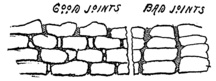
Fig. 273. How to Build a Wall.
a piece of tin and
tacked it over the
log. The tin also
extended over the
top log of the
opening. Then
we went on with
the building of the chimney walls, carrying them up about a
foot above the ridge of the roof. Our chimney was completed
by paving the bottom with stones, well packed in mud
and nicely smoothed off to make the hearth. The hearth
extended about 18 inches into the cabin, and was framed with
logs, as shown in Fig. 275.
The Floor of the Cabin.
A number of logs were now laid on the ground to serve as floor beams. Slabs were used for the floor. We had some trouble in making the floor perfectly even, because the floor beams were rather irregular, and a great deal of time was spent in smoothing the logs off to a common level. If we had the work to do over again we would have bought two or three planks and laid them on edge to support the flooring.
The Door Hinges and Latch.
269A door was now constructed by battening together a number
of slabs. In place of a hinge a hole was drilled into the
sill and another into the lintel directly in line with it. Two
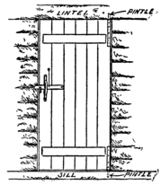
Fig. 276. The Door Hinges.
sticks of wood were then whittled to fit snugly, but without
jamming, into these holes. These sticks were then nailed to
the inner face of the door, with their whittled ends projecting
into the holes, forming
pintles on which the
door could turn. A narrow
strip of wood was
nailed to the outer jamb
for the door to close
against. The latch consisted
of a stick of wood,
fastened to the door at
one end with a nail. It
hooked onto a catch
whittled out of hard
wood to the form illustrated in Fig. 278, and nailed to the
jamb. Then to keep the latch from dropping too far when
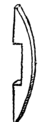
Fig. 277. The Latch Guard.
the door was open, and to guide it when slammed against the
catch, we whittled out a guard piece to the form illustrated
in Fig. 277, and nailed this to the door, with the latch projecting
through the slot of the guard. A string was now
fastened to the latch and passed through a hole in the door.
270
A block was tied to the end of the latch string to
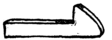
Fig. 278. Door Catch.
prevent it from slipping back through the hole;
but at night, when we did not want to be molested
by any intruders, we untied
the block and drew
in the latch string.
The Window Sash.
For our windows we made wooden sashes which fitted
nicely into the window openings. A small hole was drilled
through the sash at each side into the frame, and nails inserted
in these holes held the sash in place, and served also
as hinge pins for the sash to turn on. The sash could be
taken out at any time by removing
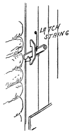
Fig. 279. The Latch.
these nails. As we
could not afford to use glass
for our windows, we covered
the sashes first with cloth, and
later, when it occurred to us
that in winter time it would be
difficult to keep the cold air
out, we used oiled paper.
Bunks.
Our next work was directed toward providing sleeping accommodations in the log 271 cabin. A large log was laid on the floor the full length of the cabin, as far out as possible without interfering with the opening of the front door. Stakes were laid across this log, with their opposite ends wedged in between the logs of the wall. A nail or two in each slab held it in place. This formed a sort of shelf 12 feet long, which was divided at the center to form two bunks, each wide enough for two persons. But as there were six of us in the society, we had to provide two more berths. A stout post was set into a hole in the ground, 272 and nailed firmly at the bottom to the lower berth log and at the top to one of the roof beams. This post supported a second berth log, which extended the full length of the building at a height of about 3 feet from the floor, and was wedged at the ends between the logs of the house. Cleats were nailed to the walls under this berth log to make it perfectly secure. Then slabs were nailed across it to form the two bunks.
Stopping up the Chinks.
The log cabin was completed by stopping up all the chinks between the logs of the walls. Strips of wood and bits of bark plastered with mud were driven into all the cracks and crevices until everything was made perfectly tight.
When our log cabin was completed we immediately transferred our camp from the tent to the hut. But at the very outset we were confronted with the problem of getting drinking water. We hadn’t thought of that before. It was easy enough to move the filter barrels, but when it came to moving the water wheel we could find no suitable place for it anywhere near the log cabin. The water of Lake Placid was too quiet, while the mill-race and the rapids on the other side of Kite Island ran so swiftly that we were afraid the water wheel would be swept away with its course. The matter was carefully considered at a special meeting of the society. It occurred to Bill that we might build a windmill in place of the water wheel, and use it to pump water from a well which could be dug near the hut.
“We wouldn’t have to use a filter, then,” he said.
“Why not?” I asked.
“Why, because the sand of the island will strain out all the dirt in the water. You see, the water in the well will have to soak in from the river, and by the time it gets through all the gravel and sand between the river and the well it ought to be filtered pretty clear.”
Digging the Well.
274That sounded logical, and so we adopted the plan at once.
We chose a spot quite near the hut for our well. When we
had dug down about 6 feet we struck water, but continued
excavating until the water lay 3 feet deep in the well.
While making the excavation we shored up the sides with
planks, to prevent the loose soil from falling in on us and
smothering us, as it so nearly did when we were digging our
first cave. By “shoring,” I mean we lined the walls with
planks, which were driven into the ground with large wooden
mallets. The planks were braced apart with sticks at frequent
intervals. As the well hole grew deeper we had to
rig up a bucket to haul the dirt out. Our bucket was a soap
box attached to a rope, which
passed through a pulley at the
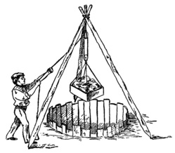
Fig. 282. Digging the Well.
top of the well. The pulley
was supported by a tripod
made by firmly lashing
together the
upper ends of
three stout
poles and
spreading their
lower ends far
enough apart
to straddle the
275
mouth of the well, as shown in Fig. 282. After the well
had been carried down to a sufficient depth, we began laying
the stone wall, which was to form the permanent lining. We
knew that the wooden walls would not do, because they would
soon decay. Our stone wall, which
was built up of flat stones like the
chimney of the log house, was not
very strong, I fear, and had not the
soil around it been pretty firm it
would probably have caved in.
However, if it served no other
purpose, it formed a fairly good
finish for the well.
The Windmill Tower.
The mouth of the well was carefully covered with planks while we constructed the windmill above it. For the tower of the windmill we chose four long sticks. They must have measured about 16 feet in length, and were from 4 to 6 inches in diameter. With them we made two frames of the form given in Fig. 283, using slabs to brace them apart. These frames were now set in position, with their lower ends firmly planted in holes in the ground, and the tower was completed by nailing on a number of 276 diagonal braces. A couple of boards were nailed across the upper ends at opposite sides, and holes were drilled through them to provide bearings for the wind wheel shaft.
The Crank Shaft.
The shaft was a piece of heavy iron rod which we procured
from the blacksmith at Lumberville. Under Bill’s
direction the blacksmith hammered a U-shaped bend at the
center of the shaft, so as to form a crank, and then he flattened
the rod near the ends (see Fig. 284). When the shaft
was set in its place these flat spots lay just outside of the
bearing boards, and
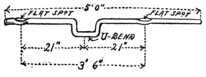
Fig. 284. The Crank Shaft.
then, to keep the
shaft from sliding
back and forth in its
bearings, we fastened
on two clamps
over these flattened parts. The clamps were made of pairs of
hardwood blocks bolted together in the manner indicated
in Fig. 285.
The Wind Wheel.
277Our next task was to construct
the wind wheel. First
we procured three boards, each
3 inches wide and 3-1/2 feet
long. A 1/2-inch hole was
278
drilled in the center of each
board, and then, with these
holes coinciding, the boards
were nailed together, with
their ends projecting, like
spokes, equally distant from
each other. Six wedges were
now made of the size indicated
in Fig. 286. These were made of a 2 x 4-inch scantling,
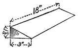
Fig. 286. Wedge for Wind Wheel.
sawed diagonally in two and then planed down to the given
dimensions. The wedges were now nailed firmly to the spokes,
as shown in Fig. 286. For the blades we used six thin
boards, each about 4 feet
long. Each blade measured
10 inches in width
at the outer end, and
tapered down to a width
of 3 inches at the inner
end, as illustrated in Fig.
288. The blades were
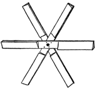
Fig. 287. Spokes of Wind Wheel.
now securely nailed to
the wedges, and their
outer ends were braced
together by means of
wires stretched from the forward edge of each blade to the
rear edge of the next one ahead. The wheel was then fitted
onto the shaft and nailed to one of the clamps. In this way
it was practically keyed to the shaft.
We did not make any vane for our windmill. It did not
need any. The wind nearly always blew either up or down
the river, more often up the river, for the prevailing summer
winds in that part of the country are southerly. But,
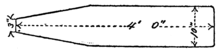
Fig. 288. Wind Wheel Blade.
aside from that,
east and west
winds could not
very well reach us
on account of the hills on both sides of the river. The wheel
was set facing the north, because the strongest winds came
from that direction, and as an extra brace against these winds
we stretched wires from the projecting end of the shaft to the
center of each blade.
A Simple Break.
A brisk northerly wind was blowing when we set the wheel in place, and it began to revolve at once, before we could nail it to the clamp. To stop it we nailed a stick of wood to the tower, so that its end projected in the path of 279 the blades and kept the wheel from turning around. This brake was swung up to the dotted position illustrated when we were ready to have the wheel revolve, but it could be thrown down at any time to stop it.
The Pump.
Our pump was made of a galvanized leader pipe; that is, a pipe used to carry off rain water from the roof of the house. The pipe was only about 8 feet long, and so we had to piece it out with a long wooden box pipe. A block closed the lower end of this box, and the leader pipe fitted snugly into a hole in the block (Fig. 291). A spout was set into the upper end of the box pipe to carry the water to the cask, which was to serve as our water reservoir.
The Pump Valves.
280We plugged the bottom of the leader pipe with a block
of wood, in the center of which a large hole was drilled.
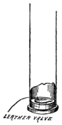
Fig. 292. The Lower Valve.
The hole was covered with a piece of leather nailed at one
side, so that it could lift up to let water
into the pipe. The piston was made of
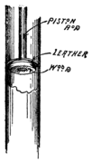
Fig. 293. The Piston Valve.
a disk of wood of slightly smaller diameter than the inside
of the pipe, and over it was fastened a piece of leather just
large enough to fit snugly against the walls of the pipe.
This piston was fastened to a wooden rod long enough to
reach from well within the pipe to the wind wheel shaft.
A strip of brass was bent over the crank, or U-shaped
281
bend in the shaft, and its ends were
fastened to the rod.
Action of the Pump.
It was rather a crude pump, but it did all the work we required of it. As the wheel went around the crank shaft would move the piston up and down. Whenever the piston went down, the air in the pipe would press up the edges of the leather disk and squeeze past (see Fig. 295). Then when the piston came up again, the leather disk, being backed by the wooden disk beneath it, was kept flat, so that no air could force its way back into the pipe. This made a partial vacuum in the pipe, and the water from the well rushed up through the valve at the bottom to fill it (see Fig. 296). When next the piston went down the bottom valve closed and more air forced its way past the piston. Then on the next upward stroke more water flowed into the pipe, until, after a number of strokes, all the air was pumped out and the water which took its place began to force its way up past the piston and eventually to flow out of the spout into the cask.
Our old windmill was sold to a farmer near Lumberville when we broke camp that fall. We carted it over and set it up for him. A number of years later I saw it still faithfully 282 at work pumping water for his cattle. The original pump had been worn out and a new one substituted, but otherwise the old windmill remained just as we had first rigged it up.
“About all we lack now,” said Dutchy, when the windmill had been completed, “is a railroad.”
“Then suppose we build one,” was Bill’s unexpected rejoinder.
We all thought he was joking, but he wasn’t.
“I don’t mean a steam railroad,” he said, “but a gravity railroad.”
“A what?”
“A gravity railroad. Oh, you know what that is–a roller toboggan–the kind they have down at Coney Island.” And he went on to explain how we could rig up a simple roller toboggan on our island.
His plan was to build an inclined trestle on the high ground just below the lagoon, and then run wooden tracks along the shore down to the pontoon bridge, and across the mill-race to Kite Island. We started first to dig a road down to the bridge, because the bank was quite high at this point. The task was rather greater than we anticipated, but we kept steadily at it until we had cut a fairly good road through the bank, though the grade was rather steep.
284Before proceeding with the trestle and track we thought the best plan would be to build our car, and then we could use it as a gauge to determine how far apart the rails should be set.
The Car.
First we got a 2 x 4-inch scantling, and cut from it two
lengths, each 4 feet 6 inches long. These were laid on edge
just 30 inches apart, and then a number of boards were
nailed across from one
scantling to the
other and sawed
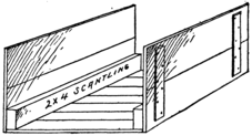
Fig. 297. Putting the Car Body Together.
off flush with
their edges. The
floor thus formed
was now turned
over so that the
scantlings lay uppermost
and the sides of the car were then nailed on with
their edges overlapping the ends of the floor boards. The
sides, which were about 18 inches high, were each made of
two boards firmly battened together. Great care was taken to
securely nail both the flooring and the sides to the scantlings,
because these scantlings were to carry the wheels of the car.
The car body was completed by nailing on the end pieces
which overlapped both the flooring and the side walls.
The Flanged Wheels.
285Next we sawed out the wheels of our car. From a board of hardwood 3/4 of an inch thick four disks, 12 inches in diameter, were sawed out. Then from a board 1 inch thick four 9-inch disks were sawed out. We cut these disks in the same way as we had made the disks for our surveying rod (see page 78), by making cuts across corners and finally smoothing off the angles with a draw-knife. A half-inch hole was now drilled in the center of each disk. Then on each large disk a smaller one was placed, with the center holes of the two coinciding and the grain of one lying across the grain of the other. In this position they were firmly nailed together, making a wheel like those used on a railway car, with the small disc forming the tread of the wheel and the large disk serving as a flange.
The Car Axles.
For the car axles we bought four 1/2-inch bolts, 6 inches
long, with two washers and two nuts for each bolt. In
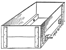
Fig. 299. Car Body with Axles in Place.
each side of the car, about 8 inches from the ends, we nailed
face blocks; that is, blocks of wood for the wheels to bear
286
against. These face blocks were
only 1/2 inch thick. Then in
these blocks holes
were drilled which
were carried clear
through the scantling.
The holes
were just large
enough for the bolts
to fit snugly in
them. The bolts were inserted from the inside, so that their
threaded ends projected out at each side of the car. A patch
of wood was nailed to the scantling over each bolt head to
prevent the bolt from slipping back into the car. Then the
wheels were mounted on these
bolts, which served as axles.
Mounting the Wheels.
First a washer was placed on the axle, then the wheel was applied, with the larger or flange disk against the face block, after which another washer was slipped on. A nut 287 was screwed against this washer just tightly enough to keep the wheel snugly in place, and yet let it turn freely on its axle. Then to keep this nut from shaking loose a second nut was screwed on against it. While one fellow held the first nut from turning, another screwed the second nut against it as tightly as he could. The second nut is technically known as a “jam nut,” or “lock nut.” The car was completed by laying a couple of boards across from one scantling to the other to serve as seats.
The Railway Track.
The trestle was now begun. First we erected a level platform,
which was to be the starting point of the railway.
This was made very substantial by planting the corner posts
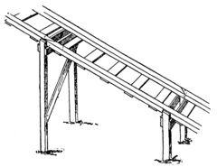
Fig. 301. The Inclined Trestle.
firmly in the ground and then bracing them together with
diagonal braces. A couple of planks leaning against the
platform at one side provided a convenient
means for mounting to the top. From
the platform the trestle ran down
at an easy incline to the
ground. It was made
of 2 x 4-inch
scantlings supported
at intervals
on posts
driven into the
ground. The opposite
288
posts were firmly braced with boards fastened diagonally
across them. The scantlings were to serve as rails, and
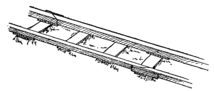
Fig. 302. Joints of the Track.
so we fastened them at the proper distance apart with ties
nailed to the under side. But to be sure that the rails were
not too far apart or too close together, the car was rolled
over the track and the rails were
set to keep the tread disks of
the wheels on them
and the flange disks
just clear of their
inner edges. The
ends of the rails
were cut off at an angle, making a slanting joint, as shown in
Figs. 301 and 302. They were fastened firmly together by
nailing a piece of board on the bottom and also on the outer
side.
The Carpenter’s Miter Box.
To make sure that the ends were all cut to the same angle,
we made a carpenter’s “miter box.” Two sideboards were
nailed to a baseboard, making a trough large enough for
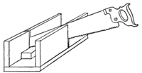
Fig. 303. Carpenter’s Miter Box.
the scantling to be
set in it. Then we
sawed through the
sides of the trough
at an angle of 45
degrees. When we
wanted to cut the end of the scantling at an angle it was
289
placed in the trough, and with the saw set in the saw cuts,
as a guide, we were sure that they would all be cut at the same
angle.
Laying the Track.
From the bottom of the inclined trestleway we continued the track down the slope to the river; but for the sake of economy, instead of using 2 x 4-inch scantlings for the rails, we bought a number of 2-inch planks at Lumberville, and had them sawed up into strips 2 inches wide. These 2-inch square rails were fastened together with slabs nailed on at frequent intervals. To maintain the proper gauge the car was rolled over each pair of rails, which were nailed first at the ends and center. To anchor the track we drove short posts into the ground so that their upper ends lay flush with the surface. A post was provided under each joint and one under the center of each rail, and then the slab ties were nailed securely to these posts. In imitation of a full-sized railway, we made it a point to “break joints” on our track; that is, to make the end of one rail come in line with the center of the 290 opposite rail, as shown in Fig. 302. Our track was continued across the pontoon bridge and ran around the west shore of Kite Island. The track was straight as far as the shore of Kite Island, whence, by an easy curve, it was carried around to the log cabin.
The First Railway Accident.
Dutchy was the first one to try the railway. He sneaked back to the platform while the rest of us were putting a few last touches on the track. The first we knew the car came tearing down the track at full speed, with Dutchy yelling at the top of his voice for us to get out of his way. Bill was on the bridge when the car came along and he had no time to run for shore, but with great presence of mind he jumped into the water and clung to one of the barrels. But the joke of it all was that Dutchy himself got a wetting too. The track at the middle of the bridge was not quite true to gauge. It was this very spot that Bill was fixing up when Dutchy came along. The end of a rail was bent in far enough to catch the flange of one of the car wheels, and in a moment Dutchy, car and all, was slung head over heels into the mill-race. Fortunately no serious harm was done. Dutchy landed a little ways down-stream, and Reddy, by quick work, managed to rescue the car just as it was floating off under the suspension bridge. The car was undamaged except that the flange of a wheel was split off.
Of course, Bill was as mad as a hornet at Dutchy, and 291 expressed his feelings in no mild terms. But his anger was somewhat tempered by the fact that Dutchy received as bad a punishment as he had inflicted.
Testing the Track.
We had to cut a new flange disk for the broken wheel, and to prevent the flanges from splitting off again we nailed a batten across the inner face of each wheel extending down to the very edge of the flange disk. This batten was fastened on across the grain. When everything was completed the car was started down the track empty to see if it would keep the rails. It went beautifully as far as the bridge, but was too light to run much beyond. The next time we loaded it up with stones and had the pleasure of watching it sail down hill, across the bridge and vanish out of sight around the shore of Kite Island. That was demonstration enough. We knew it would carry us safely and it did. The next time we tried it four of us piled into the small car, and in a moment we were off on a most thrilling ride, which ended right in front of the log cabin, where the car came to a sudden stop after riding off the end of the rails and plowing through the sand for a short space.
There is one more piece of work done by our society which yet remains to be described, and that is the cantilever bridge. This we all voted to be the greatest of our achievements on the island. To be sure, it was Uncle Ed’s design, but I think we justly deserve credit for the masterful way in which it was erected. In our search for types of bridges before building the king post bridge, we came across a simple cantilever bridge that didn’t look very difficult to construct. To be sure, none of us knew a thing about stresses and strains, and ingenious though we were, Bill realized that the task of designing a cantilever bridge was far beyond him. Nevertheless, we were sure we could build one if only we had a good set of plans. A letter was therefore mailed to Uncle Ed, asking him for the required details. The answer came promptly from Western Australia, asking us to send him the exact width of the water we wished to span, the depth of the water, the distance from the top of one bank to the top of the other, and the exact height of the banks above water level. We decided we would build the bridge across the mouth of the lagoon. The distance here between the two banks measured a little over 60 feet. The banks 293 were very precipitous, and rose 13-1/2 feet above the level of the water. All these details, together with soundings of the bottom, all the way across, were sent to Uncle Ed, and on the day after our railway was completed quite a bulky package was received in answer. It contained complete directions for building the bridge of wooden frames, which were so designed that they needed merely to be hooked together to form the bridge, though to make the structure perfectly safe Uncle Ed cautioned us to tie the frames together wherever they met.
I am half afraid to tell my readers how to build this bridge, as it required the utmost care, and had to be built just so to avoid disaster. Bridge building is a serious business, and I would not advise any one to attempt building this, of all bridges, who does not propose to follow instructions implicitly. Uncle Ed told us that if we built it properly, and with sound timbers, we would find the bridge strong enough to support a dozen boys, but he warned us not to crowd more than that number on it.
Frames for the Cantilever Bridge.
The frames with which the cantilever bridge was built
were made of saplings from 3 to 4 inches in diameter. We
procured them from Mr. Schreiner’s lands up the river. In
making the frames the sticks were fastened together with
1/2-inch bolts 6 inches long. It was quite a strain on our
pocketbooks to buy these bolts, but Uncle Ed had written
294
that nails or spikes would
be useless to stand the
strains of so large a
bridge, and that if we
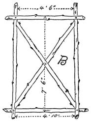
Fig. 306. B Frame (make four).
could not get any bolts
we had better give up the
idea of building a cantilever
bridge. To make
sure that we made no
mistakes, Uncle Ed had
made a drawing of each
different size of frame we
would need, designating
each with a different letter,
and then these same letters
were marked on a general
view of the bridge, so that
we would know exactly
where the frames belonged.
These drawings are reproduced
here in Figs. 305 to
316 and 318. We had to
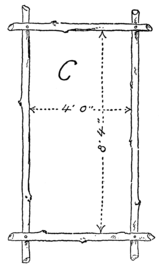
Fig. 307. C Frame (make four).
make four frames each, of
the A, B, C and E sizes,
two each of the F, G and L
295
sizes and one each of the H, I, J and K sizes. Of the D
frames two were made with the ends cut away on the outer
half, as illustrated in Fig. 308, and two were cut away at
the inner side, the reason for which will appear presently.
When fastening the timbers together
we cut notches in each
stick, as shown in Fig. 317.
The depth of each notch was
just one-quarter the diameter
of the stick; that is, the notch
was 3/4 of an inch deep in a
3-inch stick and 1 inch deep in a
4-inch stick. Care was taken not
to exceed this depth, for fear of
weakening the sticks. In the
case of frame D, the sticks were
not notched or mortised together.
It will be noticed that the measurements
are given to the inner
edges of the sticks in some cases,
and to the outer edges in others.
The reason for this, as Uncle Ed
explained it, was because the
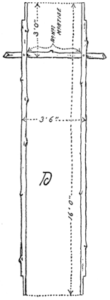
Fig. 308. D Frame (make four).
thickness of our sticks would
vary considerably, and it was
important that many of the measurements
be exact, otherwise the
frames would not fit into each
296
other as they should. Another
thing to which he
called our attention was the
fact that frames A, B, E, F,
H, K and L were stiffened
with cross braces, while the
rest were not. The braced
frames, he wrote, were
those which would be under
a compression strain, while
the others would be under
tension; that is, when any
weight was placed on the
bridge it would push against
the ends of the braced
frames, trying to crush
them, but would pull on the
unbraced frames, trying to
tear them apart. In fact,
the bridge would have been
just as strong had we used
heavy iron wire in place of
the unbraced frames, and
the only reason Uncle Ed
did not recommend our
doing so was because we
had no simple way of
stretching the wire taut.
Erecting the Towers.
299We built the complete set of frames before attempting to
erect the bridge. Then we began by building the towers.
Two A frames were set on end and spaced 4 feet apart at the
top and 5 feet apart at the bottom, measuring not from the
inner but from the outer edges of the frames. In this position
they were connected by short spars, notched in place.
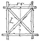
Fig. 316. L Frame (make two).
The notches for these connecting spars will be seen in Fig.
305 on the main or vertical timbers of frame A, just below
the upper and middle cross sticks and above the lower cross
sticks. The upper connecting spars were wedged tightly
under the cross sticks, and served as an additional support
for them. Diagonal braces were nailed from one frame to
the other, as illustrated in Fig. 318. The towers were built
Fig. 317. Notching the Sticks Together.
300
on opposite banks, at the mouth of the lagoon, and when
completed we lowered them carefully down the banks into
the water. According to directions they were to be set just
30 feet apart, measuring from the center of one tower to
the center of the other. The water was quite shallow where
the towers rested, but the bottom was
pretty firm. Holes were dug in the
bottom for the legs of the tower to set
into, and then large stones were piled
around each leg to provide a firm
foundation for the towers.
Setting Up the Frames.
A B frame was now hauled out to one of the towers and lifted by its narrower end, with fall and tackle, until its lower tie piece rested on the projecting ends of the center crosspieces of the tower. The upper end of the frame was held against the top of the tower, while a C frame was hooked over the upper ends of the tower legs; then frame B was allowed to swing outward until its smaller end locked with the outer end of frame C. It will be observed in Fig. 306 that the upper crosspiece or tie piece of frame B was fastened to one side of the vertical sticks and the lower tie piece to the other side. This was done purposely, so that when the frame was set in position the bottom tie piece would be on the lower side of the frame and the top piece would lie on the upper side, as shown in Fig 318, or, better still, in 301 Fig. 319. The rest of the frames were all arranged to be set in place with their tie pieces on the lower side, or facing the towers, as will be clearly understood by examining the illustrations. As soon as the B and C frames were set up on one side of the tower, another pair of B and C frames was set up on the other side of the same tower. A cantilever bridge must always be built out on both sides of the tower at the same time, otherwise it will be overbalanced on one side and topple over. After the B and C frames were in place we took two D frames, with oppositely cut ends, and rested their tie sticks on the top of the tower, just under the ends of the C frames. The ends of the two D frames overlapped at the center of the tower, and, as one was cut away at the outer side and the other at the inner side, they fitted neatly together and were fastened with bolts. The D frames were 302 supported near their outer ends with E frames, which rested on the B and C frames. Fig. 319 shows an E frame set in position on the landward side of the tower, while two of the boys are climbing out on the opposite B and C frames preparatory to setting up the other E frame. A cross stick was now bolted to each D frame, just beyond the upper ends of the E sticks. This done, the frame F was hooked in between the ends of B and C, at the shoreward side of the tower, and its outer ends were supported by frame G, which was hooked over frame D and the upper ends of frame E. The frame L was then rested on the ends of frame F and G, and supported the shore end of frame D. A stick nailed across frame D on 303 each side of the upper ends of frame L served to hold the latter in place.
Binding and Anchoring the Structure.
As the different frames were coupled together, we bound the overlapping ends with soft iron wire. The place where frames B, C, E and F came together was quite a vital point, and we took pains to make the wire binding at this place doubly strong. As soon as the L frame was in place we anchored the bridge to shore by running wires from the ends of the D frame and the ends of the G frame to stakes driven into the banks. The frames on the second tower were now similarly erected and anchored, after which we were ready to put in the center panels of the bridge.
The Center Panels of the Bridge.
304First, the frame H was wedged into place and thoroughly fastened by a liberal winding of wire. Next the frames I and J were set in place, and in order to do this we had to remove the upper tie pieces of these frames. Then one frame was hooked in the other, and the two were carried out on the scow under the center of the bridge. Ropes were tied to the ends of the two frames, and they were lifted together, like a wide V, to the position shown in Fig. 318, after which the tie pieces were bolted on again, resting against the ends of the E frames. As an additional security, two sticks were bolted to the under side of the frame H, one at each side of the I and J frames. The bridge was then completed by wedging the frame K under the ends of the D frames, and also placing a stick across each tower under the joints of the D frames. We planned to run our gravity railway across this bridge, moving our platform and trestle to the opposite bank; so instead of flooring our bridge with slabs, we fastened ties across at intervals of 15 or 18 inches. These ties were sticks 3 inches in diameter, which were secured to 305 the D frames.
A Serious Interruption.
We were just preparing to lay the tracks across the bridge when we met with a serious interruption. Mr. Halliday had told us that a few days before our arrival that summer Mr. Smith, the owner of the island, and another man had paid 306 a visit to the place. Jim Halliday himself had rowed them over, and learned from their conversation that Mr. Smith was trying to sell the island, and that the stranger, a Mr. Gill, was a prospective purchaser. All summer long we had been dreading the return of this customer, though, as time passed without his putting in an appearance, we almost forgot the incident. But now, at the end of August, just as we had about completed our cantilever bridge, who should arrive but this very man Gill and three other men with a large tent and camping outfit. It was a sorrowful crowd of boys that watched the wagon with their belongings ford the shallow water over to our island. We felt that the island was ours by right of discovery and occupation, but we were powerless to force our claims. And what if they did not insist on our leaving the island? It would not be the same place with strangers around to meddle with our things.
Dispossessed.
But the new owner of the island was even more of a boor than we had anticipated. As soon as he landed he wanted to know what we were doing on his property, and peremptorily ordered us off. Bill answered that we were camping there, and politely asked if we couldn’t stay out the summer. But Gill would not listen to the idea. We must get off the island that very day or he would see to it that we did.
I tell you it made us boil. We were just itching to give the pompous little man the sound thrashing he deserved, but 307 knew that we would stand a very small show against his three powerful companions. At any rate, we were determined not to leave at once. Instead, we repaired to Kite Island, taking our belongings with us. Then we cut away the suspension, spar and pontoon bridges, so that we would not be annoyed by any of the Gill crowd. We were resolved that they should not benefit by any of the things we had built.
At the dead of night we paddled back to Willow Clump Island, crept past the slumbering intruders and waded out to the old water wheel. After a good deal of exertion we managed to dislodge the smaller tower, letting the wheel drop into the river and float away. Then we made for the cantilever bridge. It didn’t take us very long to cut away the wire bindings, unhook the frames and drop them into the lagoon. But the task was quite a perilous one, as the night was pitch black. Finally, nothing remained of the bridge but the two towers, which were left as monuments to mark the spot where our last piece of engineering on the island was done.
Farewell to Willow Clump Island.
We spent several days on Kite Island, knowing that we were safe from intrusion, because the Gill crowd had but one boat, and that was on the Jersey side of the island. We felt confident that they would not take the trouble of wading around Point Lookout with their boats, as we had done; nevertheless, to prevent a surprise, we kept a sentry posted on the Lake Placid side of the island and gathered a pile of 308 stones for ammunition. But our fun was spoiled, and we finally decided to break camp and bid farewell forever to Willow Clump Island and its vicinity. Our goods were ferried over to Jim Halliday’s farm, where we were given shelter. The windmill, as I have already stated, was sold to a farmer at Lumberville, and we were kept busy for several days carting it over and setting it up in place. When everything had been done we stole back to Kite Island and set fire to the log cabin. The next day Mr. Schreiner took us home in a couple of his wagons. Thus ended our “investigation, exploration and exploitation of Willow Clump Island.” The work of two summers was practically all destroyed in a few days.
Reddy’s Cantilever Bridge.
I believe I have given a careful account of everything that was recorded in the chronicles of the society. We were too discouraged to undertake anything new in the two weeks before school opened. I presume I might mention here Reddy’s cantilever bridge, which, however, had really nothing to do with the S. S. I. E. E. of W. C. I., because our society was formally disbanded the day before Bill and I returned to school. About a month after leaving home I received a letter from Reddy inclosing three interesting photographs, which are reproduced herewith. Reddy certainly had the bridge fever, because soon after we had left he started to work, with the rest of the boys, on a cantilever bridge across Cedar Brook. The brook was entirely unsuited to such a 309 structure, because the banks were very low; but he made the towers quite short and built an inclined roadway leading up to the top of them. The legs of the towers were driven firmly into the bank, making them so solid that he thought it would be perfectly safe to build the frames out over the brook without building them at the same time on the shore side. But he had made a miscalculation, for when a couple of the boys had crawled out on the B and C frames to set up an E frame the structure commenced to sag. The trouble was remedied by propping up the tower with a stout stick driven into the river bottom and wedged under the upper tie piece of the tower. The towers were really too short to make a well proportioned bridge, for the panels had to be made very long and narrow, so as to reach across. But on the whole it was a very creditable structure when completed, though it had only half as long a span as our cantilever bridge over the lagoon.
INDEX
A
“A” tent, 207
Abbreviations, wigwag, 146
Accident, railway, the first, 290
Ainu snow shoe, 41
Alarm clock, a unique, 63
Alphabet, wigwag, 145
Alpine stock, 198
Anchoring cantilever bridge, 303
Annex, the, 50
Arctic expedition, 193
Armchair, barrel, 227
Axles of railroad car, 285
B
Bags, sleeping, 203
Banquets, midnight, 179
Barrel armchair, 227
Barrel filter, 68
Barrel hoop snow shoe, 36
Barrel stave hammock, 226
Barrel stave snow shoe, 36
Bat’s wings, 33
Bed, a camp, 209
Bed in shower, 210
Belly band, elastic, 235
Bending wood, 39
Bicycle wheels, mounting frame on, 219
Big Bug Club, 177
“Bill,” 17
Bill’s cave, 224
Bill’s skate sail, 21
Binding cantilever bridge, 303
Blades of wind wheel, 278
Boat, ice, 159
Boat mooring, tramp-proof, 142
Boat, scow, 59
Box kite, diamond, 236
Box, the black walnut, 19
Brake for wind wheel, 278
Bridge building, 95
Bridge, cantilever, 292
Bridge, king post, 105
Bridge, king rod, 102
Bridge, pontoon, 101
Bridge, Reddy’s cantilever, 308
Bridge, spar, 95
Bridge, stiffening, 104
Bridge, suspension, 99
Bridge wreck, 66
Bucket, the canvas, 251
Buckets for water wheel, 246
Bunks, 270
C
Camp bed, 209
Camp bed in shower, 210
Camp, breaking, 158
Camp chair, a, 208
Camp fire, a costly, 200
Camp fire, kindling, 194
Canoe, Indian paddling, 121
Canoe lee boards, 119
Canoe rudder, 115
Canoe, the sailing, 111
Canoe sails, 117
Canoe, scooter, 190
Canoe, stretching on canvas, 114
Canoes, canvas, 109
Cantilever bridge, 292
Cantilever bridge, anchoring, 303
Cantilever bridge, binding frames, 303
Cantilever bridge, center panels, 304
Cantilever bridge, frames for, 293
Cantilever bridge, Reddy’s, 308
Cantilever bridge, setting up frames of, 300
Cantilever bridge towers, 299
Canvas bucket, 251
Canvas canoes, 109
Canvas, stretching on canoe, 114
Canvas tent, 46
Car axles, 285
Car for gravity railroad, 284
Car, mounting wheels on, 286
Carpenter’s miter box, 288
Cave, Bill’s, 224
Cave, covering the, 177
Cave, excavating for, 173
Cave, framing, 174
Cave-in, a, 171
Center panels of cantilever bridge, 304
Chain, surveyor’s, 77
Chair, a camp, 208
Chair seat snow shoe, 35
Cheek blocks, 162
Chinks in log cabin, stopping up, 272
Christmas vacation, 19
Clamp for crank shaft, 276
Clapboards, nailing on, 135
Cleat, a, 163
Climbing, mountain, 198
Clock, a unique alarm, 63
Club, the Big Bug, 177
Club pin, 180
Club, the Subterranean, 171
Code, International Telegraph, 155
Combination lock, 181
Council of war, 139
Crank shaft, the, 276
Creepers, ice, 170
Crossbow, 55
Crossbow trigger, 57
Cutting out disk, 78
D
Danish sail, 30
Derrick, the, 131
Diamond box kite, 236
Digging the well, 274
Disk, cutting out, 78
Disk, sighting, 79
Dispossessed, 306
Diving tree, 84
Door hinges, 269
Door latch, 269
Doors, sliding, 136
Double mirror heliograph, 156
Double surprise, 140
Drill, fire, 69
Drowned, how to restore, alone, 92
Drowned, restoring the, 89
E
Easter vacation, 224
Elastic belly band, 235
Expedition, Arctic, 193
Expedition, logging, 255
Expedition, preparing for, 53
Exploration, preliminary, 66
F
Farewell to Willow Clump Island, 307
Fastener, brass, 58
Filter, the barrel, 68
Filter barrel, cooling the, 250
Filter, the small, 67
Fire drill, 69
Fireplace of log cabin, 265
Fireplace, outdoor, 195
Fireplace, stone-paved, 196
Fissure, path up the, 129
Flanged wheels, 285
Fly, ridge pole, 54
Fly for tent, 54
Fly, umbrella with, 211
Focusing heliograph instrument, 153
Frame on bicycle wheels, 219
Frames for cantilever bridge, 293
Frames of cantilever bridge, setting up, 300
Friend in time of trouble, 201
G
Goblins’ Dancing Platform, 126
Grass hut, 124
Gravity railroad, 283
H
Halliday, Jim, 194
Hammock, barrel stave, 226
Harness, pack, 212
Heliograph, the, 147
Heliograph, double mirror, 156
Heliograph instrument, focusing, 153
Heliograph screen, 151
Heliograph sight rod, 150
Heliograph signaling, 154
Heliograph, single mirror, 148
Hinge for spars, 30
Hinges, door, 269
House building, 124
House, log, 254
House, the tree, 132
Hut, cold night in, 197
Hut, log, 254
Hut, straw, 124
I
Ice boat, the, 159
Ice boats, sledges and toboggans, 158
Ice, craft strikes the, 184
Ice creepers, 170
Indian paddling canoe, 121
Instrument, double mirror, 156
Instrument, single mirror, 148
Instrument, surveying, 73
International Telegraph Code, 155
Iroquois snow shoe, 39
Island, mapping the, 82
Island, off to the, 63
Island, trip to the, 64
J
Jacob’s Ladder, 129
Jaws of boom, 162
Jib-sail for ice boat, 164
Jib-sail for scooter scow, 187
Jim Halliday, 194
K
King post bridge, 105
King rod truss, 102
Kite, diamond box, 236
Kite Island, 83
Kite, Malay, 5-foot, 231
Kite, Malay, 8-foot, 233
Kites, putting to work, 235
Kites, tailless, 229
Klepalo, the, 70
L
Ladder, the Jacob’s, 129
Ladders, rope, 130
Lagoon, the, 83
Lake Placid, 83
Land yacht, 215
Land yacht, a sail on, 222
Lanteen sail for canoe, 117
Lanteen skate sail, 29
Latch, door, 269
Latch string, 270
Lee boards, canoe, 119
“Leg-of-mutton” sail, 220
Levels, spirit, 74
Lock combination, 181
Log cabin, 251
Log cabin, building the, 259
Log cabin door hinges, 269
Log cabin door latch, 269
Log cabin door and window frames, 263
Log cabin fireplace, 265
Log cabin, floor of, 267
Log cabin, foundation of, 254
Log cabin, roof of, 262
Log cabin, stopping up chinks, 272
Log cabin window sash, 270
Log raft, 256
Logging expedition, 255
M
Mainsail for canoe, 117
Mainsail for ice boat, 162
Malay kite, 5-foot, 231
Malay kite, 8-foot, 233
Mapping the island, 82
Mast of land yacht, stepping, 218
Mast step, ice boat, 161
Mast step, leather, 30
Mast step, wooden, 30
Megaphone, 57
Megaphone mouthpiece, 58
Midnight banquets, 179
Mill-race, the, 88
Mirror instrument, heliograph, 148
Miter box, carpenter’s, 288
Mizzen sail of canoe, 118
Mooring, tramp-proof boat, 142
Mountain climbing, 198
Mouthpiece of megaphone, 58
“Mummy case,” 204
N
Needle, weaving, 39
Night, cold, in the hut, 197
Nightmare, a, 211
Noria, 241
Norwegian ski, 42
Numerals, wigwag, 145
O
Oar, the, 61
Off to the island, 63
Organizing the society, 25
Outdoor fireplace, 195
Outfits, tramping, 203
P
Pack harness, 212
Paddling canoe, Indian, 121
Paddles for water wheel, 246
Panels, center, of cantilever bridge, 304
Path up the fissure, 129
Patient, how to work over, alone, 93
Pin, the club, 180
Plank, swimming on, 86
Platform, Goblins’ Dancing, 126
Point Lookout, 83
Pole, ridge, 48
Poncho, 210
Pontoon bridge, 101
Poor shelter, a, 199
Preparing for the expedition, 53
Protractor, the, 76
Provisions and supplies, 54
Pump, the, 279
Pump, action of, 281
Pump valves, the, 280
R
Raft, log, 256
Raft, sail-rigged, 258
Railroad car, 284
Railroad car axles, 285
Railroad flanged wheels, 285
Railroad, gravity, 283
Railway track, the, 287
Railway accident, the first, 290
Railway, rope, 97
Railway spikes, 50
Rapids, shooting the, 88
Receiving trough for water wheel, 247
Records of the S. S. I. E. E. of W. C. I., 19
Reddy’s cantilever bridge, 308
Rennwolf, the, 168
Restoring the drowned, 89
Ridge pole, 48
Ridge pole, fly, 54
Riveting, 213
Rod, heliograph sight, 150
Rod, surveyor’s, 78
Rope ladders, 130
Rope railway, 97
Rowlocks, sockets for, 60
Rudder, canoe, 115
Rudder shoe, ice boat, 160
Runner shoe, ice boat, 160
Runners of scooter canoe, 190
Runners of sledge, 165
Rustic table, 66
S
S. S. I. E. E. of W. C. I., records of, 19
Sail, jib, for scooter, 187
Sail, “leg-of-mutton,” 220
Sail, mizzen, of canoe, 118
Sail-rigged raft, 258
Sail, sprit, for scooter, 186
Sail stitch, 46
Sail through the country, 222
Sailing canoe, the, 111
Sailor’s stitch, 221
Sails, canoe, 117
Sails for ice boat, 162
Sandwiches, straw, 227
Schreiner, a visit from Mr., 110
Scooter canoe, 190
Scooter sailing, 188
Scooter scow, 185
Scooters, 183
Scow, the, 59
Scow, a sail in, 184
Scow, scooter, 185
Scow, stolen, 138
Screen, heliograph, 151
Seat, swing, 97
Shaft, the crank, 276
Shelter, a poor, 199
Shooting the rapids, 88
Sight rod, 150
Sighting blocks, 74
Sighting disk, 79
Signaling, heliograph, 154
Signals, wigwag, 144
Simple method of surveying, 79
Single mirror heliograph, 148
Sioux snow shoe, 37
Skate sail, bat’s wings, 33
Skate sail, Bill’s, 21
Skate sail, Danish, 30
Skate sail, double Swedish, 26
Skate sail, lanteen, 29
Skate sail, single Swedish, 28
Skate sails, 26
Ski, Norwegian, 42
Ski sticks, 43
Skids, 262
Slabs, 101
Sledge, the, 165
Sleeping bags, 203
Sliding doors, 136
Snotter, 187
Snow shoe, Ainu, 41
Snow shoe, barrel hoop, 36
Snow shoe, barrel stave, 36
Snow shoe, chair seat, 35
Snow shoe, Iroquois, 39
Snow shoe, Sioux, 37
Snow shoe, Swiss, 43
Snow shoes, 35
Society, meeting of, 189
Society, organizing the, 25
Spar bridge, 95
Spars, hinge for, 30
Spikes, railway, 50
Spiral spring, 153
Spirit levels, 74
Spring, spiral, 153
Sprit sail, 186
Stepping mast of land yacht, 218
Stitch, the sail, 46
Stitch, sailor’s, 221
Stick, ski, 43
Stiffening the bridge, 104
Stone-paved fireplace, 196
Stone wall, how to build, 266
Straw hut, 124
Straw sandwiches, 227
Subterranean Club, 171
Summer toboggan, 229
Supplies and provisions, 54
Surprise, a double, 140
Surveying, 73
Surveying, first lesson in, 79
Surveying instrument, 73
Surveying, a simple method of, 79
Surveying for water wheel, 241
Surveyor’s chain, 77
Surveyor’s rod, 78
Suspension bridge, 99
Swamp shoe, 43
Swedish sail, double, 26
Swedish sail, single, 28
Swimming, 84
Swimming on a plank, 86
Swing seat, 97
Swiss snow shoe, 43
T
Table, a rustic, 66
Tailless kites, 229
Telegraph Code, International, 155
Tent, the “A”, 207
Tent, annex, 50
Tent, canvas wall, 46
Tent fly, 54
Tent making, 44
Testing the track, 291
Thole pins, 61
Tie block, wood, 49
Tie, wire, 50
Tiger’s Tail, 83
Tiller, ice boat, 161
Tiller of land yacht, 219
Toboggan, the, 167
Toboggan, the summer, 229
Tower, the windmill, 275
Towers of the cantilever bridge, 299
Towers for water wheel, 243
Towers of water wheel, setting up, 248
Track, laying the, 289
Track, the railway, 287
Track, testing the, 291
Tramping outfits, 203
Tramp-proof boat mooring, 142
Tramps, trouble with, 138
Tree, diving, 84
Tree house, the, 132
Trigger for crossbow, 57
Trip to the island, 64
Tripod, the, 75
Trouble with tramps, 138
Trunk, the old, 18
Truss, king rod, 102
Turnbuckle, a simple, 216
U
Umbrella with fly, 211
Umbrella rib crossbow, 55
Uncle Ed, word from, 45
Uncle Ed’s departure, 109
V
Vacation, Christmas, 19
Vacation, Easter, 224
Valves, the pump, 280
Van Syckel, interview with, 189
Vengeance, 139
Visit from Mr. Schreiner, 110
W
Wall, how to build, 266
Wall tent, 46
Water wheel, 241
Water wheel buckets, 246
Water wheel, construction of, 245
Water wheel, Mr. Halliday’s, 252
Water wheel, mounting the, 249
Water wheel paddles, 246
Water wheel receiving trough, 247
Water wheel, surveying for, 241
Water wheel, towers for, 243
Water wheel towers, setting up, 248
War, council of, 139
Weaving needle, 39
Well, digging the, 274
Wheel, the wind, 276
Wheels for gravity railroad, 285
Wheels, mounting, on car, 286
Wheels, mounting frame on, 219
Wigwag abbreviations, 146
Wigwag alphabet, 145
Wigwag numerals, 145
Wigwag signals, 144
Wigwagging and heliographing, 144
Wigwagging at night, 147
Willow Clump Island, 23
Willow Clump Island, farewell to, 307
Willow Clump Island in winter, 194
Wind wheel, 276
Wind wheel blades, 278
Wind wheel brake, 278
Windmill, 273
Windmill tower, 275
Window hinge, 270
Window sash, log cabin, 270
Wings, bat’s, 33
Wire tie, 50
Wood, bending, 39
Wood tie block, 49
Word from Uncle Ed, 45
Y
Yacht, land, 215
Yacht, land, frame of, 216
The Most Popular Scientific Paper in the World

Established 1845
Weekly, $3.00 a Year; $1.50 Six Months
This unrivaled periodical is now in its sixtieth year, and, owing to its ever-increasing popularity, it enjoys the largest circulation ever attained by any scientific publication. Every number contains sixteen large pages, beautifully printed, handsomely illustrated; it presents in popular style a descriptive record of the most novel, interesting and important developments in Science, Arts and Manufactures. It shows the progress of the World in respect to New Discoveries and Improvements, embracing Machinery, Mechanical Works, Engineering in all its branches, Chemistry, Metallurgy, Electricity, Light, Heat, Architecture, Domestic Economy, Agriculture, Natural History, etc. It abounds in fresh and interesting subjects for discussion, thought or study. To the inventor it is invaluable, as every number contains a complete list of all patents and trade-marks issued weekly from the Patent Office. It promotes Industry, Progress, Thrift and Intelligence in every community where it circulates.
The Scientific American should have a place in every Dwelling, Shop, Office, School, or Library. Workmen, Foremen, Engineers, Superintendents, Directors, Presidents, Officials, Merchants, Farmers, Teachers, Lawyers, Physicians, Clergymen–people in every walk and profession in life–will derive satisfaction and benefit from a regular reading of the Scientific American.
If you want to know more about the paper send for “Fifteen Reasons Why You Should Subscribe to the Scientific American,” and for “Five Reasons Why Inventors Should Subscribe to the Scientific American.” Fifty-two numbers make 832 large pages, equal to 3,328 ordinary magazine pages, and 1,000 illustrations are published each year. Can you and your friends afford to be without this up-to-date periodical, which is read by every class and profession? Remit $3.00 by postal order or check for a year’s subscription, or $1.50 for six months.
MUNN & COMPANY, Publishers
No. 361 Broadway, New York City
JUST PUBLISHED
Home Mechanics
for Amateurs
By GEORGE M. HOPKINS
Author of “Experimental Science”
12mo, 375 Pages, 320 Illustrations. Price, $1.50, Postpaid
The book deals with wood-working, household ornaments, metal-working, lathe work, metal spinning, silver working; making model engines, boilers and water motors; making telescopes, microscopes and meteorological instruments, electrical chimes, cabinets, bells, night lights, dynamos and motors, electric light, and an electrical furnace. It is a thoroughly practical book by the most noted amateur experimenter in America.
Every reader of “Experimental Science” should possess a copy of this most helpful book. It appeals to the boy as well as the more mature amateur. Holidays and evenings can be profitably occupied by making useful articles for the home or in building small engines or motors or scientific instruments. Table of contents sent on application.
MUNN & COMPANY
Publishers of the “Scientific American”
361 BROADWAY, NEW YORK
Scientific American
Reference Book
500 PAGES SIX COLORED PLATES PRICE $1.50
This book is intended to furnish the reader with information not obtainable in any other work of reference. It is not an encyclopedia, nor is it an annual, but it contains a mass of information that should be within the reach of every family. This work has been prepared in response to the many thousands of inquiries received by the Editor of the Scientific American on the widest possible range of topics, and it is through these inquiries that the Editors of the Reference Book have been enabled to determine the scope of this work. It deals with the “Progress of Discovery,” “Shipping and Yachts,” “The Navies of the World,” “The Armies of the World,” “Railroads of the World,” “Population,” “Education,” “Telegraphs,” “Submarine Telegraphs,” “Wireless Telegraphy,” “Patents,” “Trade-marks,” “Copyrights,” “Manufactures,” “Iron and Steel,” “Departments of the Federal Government,” “The Post-office,” “International Institutions and Bureaus,” “Mines and Mining,” “Farms and Food,” “Mechanical Movements,” “Chemistry,” “Astronomy,” “Weights and Measures,” and a host of other subjects, such as “Aerial Navigation,” “Radium,” etc. This valuable compendium has been put at a very low price, so that it may be within the reach of every one. It is fully illustrated, and has colored plates showing the flags of all nations, the funnels and house flags of lines in American trade, and the International Signal Code.
DESCRIPTIVE CIRCULAR SENT UPON REQUEST
MUNN & COMPANY, Publishers
361 BROADWAY :: :: NEW YORK CITY