The illustrations and descriptions we give this week, entitled "How to Break a Cord," "Prestidigitation," "Circle Divider," "Sulphurous Acid," "Production of Gas," "Aquatic Velocipede," "Several Toys," "Scientific Amusements," are from our excellent contemporary La Nature.
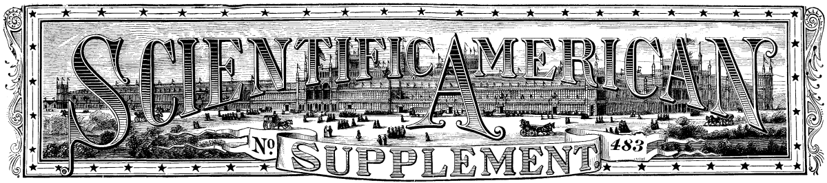
The well known surgeon, Theodor Billroth, was born on the island of Rügen in 1829. He showed great talent and liking for music, and it was the wish of his father, who was a minister, that he should cultivate this taste and become an artist; but the great masters of medicine, Johannes Mueller, Meckel v. Hemsbach, R. Wagner, Traube, and Schönlein, who were Billroth's instructors at Greifswald, Göttingen, and Berlin, discovered his great talent for surgery and medicine, and induced him to adopt this profession. It was particularly the late Prof. Baum who influenced Billroth to make surgery a special study, and he was Billroth's first special instructor.
In 1852 Billroth received his degree as doctor at the University of Berlin. After traveling for one year, and spending part of his time in Vienna and Paris, he was appointed assistant in the clinique of B. von Langenbeck, Berlin. At this time he published his works on pathological histology ("Microscopic Studies on the Structure of Diseased Human Tissues") which made him so well known that he was appointed a professor of pathology at Greifswald in 1858. Mr. Billroth did not accept that call, and was appointed professor of surgery at Zurich in 1860, and during that time his wonderful operations gave him a world-wide reputation. In 1867 the medical faculty of the Vienna University concluded to appoint Billroth as successor to Prof. Schuh, which position he still fills.
THEODOR BILLROTH.
Billroth is a master of surgical technique, and his courage and composure increase with the difficulty of the operation. He always makes use of the most simple apparatus and instruments, and follows a theoretically scientific course which he has never left since he adopted surgery as a profession, and by which he has directed surgery into entirely new channels. He has given special attention to the study of the healing of wounds, the development of swellings and tumors, and the treatment of wounds in relation to decomposition and the formation of proud flosh. He has had wonderful success in performing plastic operations on the face, such as the formation of new noses, lips, etc., from flesh taken from other parts of the body or from the face. Although Billroth devoted much of his time to the solution of theoretical problems, he has also been very successful as an operator. He has removed diseased larynxes, performed dangerous goiter operations, and successfully removed parts of the oesophagus, stomach, and intestines.
Billroth has been very careful in the selection of his scholars, and many of them are now professors of surgery and medicine in Germany, Belgium, and Austria. They all honor and admire him, his courage, his character, his humane treatment of the sick and suffering, arid his amiability.
The accompanying portrait is from the Illustrirte Zeitung.
DR. JOHN C. PETERS, of this city, in a recent contribution to the Medical Record, gives the following interesting particulars:
I have read many brilliant essays of late on these topics, but not with unalloyed pleasure, for I believe that many writers have fallen into errors which it is important to correct. No really well informed person has believed for a long time that carbolic alcohol will destroy the cholera poison; but many fully and correctly believe that real germicides will. It has been known since 1872 that microbes, bacilli, and bacteria could live in very strong solutions of carbolic alcohol, and that the dilute mineral acids, tannin, chloride, corrosive sublimate, and others would kill them.
In 1883 cholera did not arise alone in Egypt from filth, but from importation. It did not commence at Alexandria, but at Damietta, which is the nearest Nile port to Port Said, which is the outlet of the Suez Canal. There were 37,500 deaths from cholera in the Bombay Presidency in 1883. Bombay merchants came both to Port Said and Damietta to attend a great fair there, to which at least 15,000 people congregated, in addition to the 35,000 inhabitants. The barbers who shave and prepare the dead are the first registrars of vital statistics in many Egyptian towns, and the principal barber of Damietta was among the first to die of cholera; hence all the earliest records of deaths were lost, and the more fatal and infective diarrhoeal cases were never recorded. Next the principal European physician of Damietta had his attention called to the rumors of numerous deaths, and investigated the matter, to find that cases of cholera had occurred in May, whereas none had been reported publicly until June 21. A zadig, or canal, runs through Damietta from one branch of the Nile to another, and this is the principal source of the water supply.
Mosques and many houses are on the banks of this canal, and their drainage goes into it. Every mosque has a public privy, and also a tank for the ablution, which all good Mohammedans must use before entering a holy place. There was, of course, great choleraic water contamination, and a sudden outburst of cholera took place. The 15,000 people who came to the fair were stampeded out of Damietta, together with about 10,000 of the inhabitants, who carried the disease with them back into Egypt. Then only was a rigid quarantine established, and a cordon put round Damietta to keep everybody in, and let no one go out, neither food, medicines, doctors, nor supplies of any kind. Such is nearly the history of every town attacked in Egypt in 1883.
When the pestilence had been let out en masse, severe measures were taken to keep it in Cairo, for up the Nile was attacked long before Alexandria suffered. This cholera broke out, as it almost always does in Egypt, when the river Nile is low and the water unusually bad. It disappeared like magic, as it always does in Egypt, when the Nile rises and washes all impurities away. There had been little or no cholera in Egypt since 1865, and there had often been as much filth as in 1883. It has never become endemic there, as it is a rainless country and generally too dry for the cholera germ to thrive.
Marseilles had a small outbreak of cholera in the fall of 1883, probably derived from Egypt, which she carefully concealed. In addition, cholera was also brought to Toulon from Tonquin by the Sarthe and other vessels. Toulon concealed her cholera for at least seventeen days, and did not confess it until it had got such headway that it could no longer be concealed. At least twenty thousand Italians fled from Toulon and Marseilles, and others were brought away in transports by the Italian government. Rome refused to receive any fugitives; Genoa and Naples welcomed them. There were at least three large importations into Naples. The outbreak in Genoa was connected with washing soiled cholera clothes in one of the principal water supplies of the city, and Naples has many privy pits and surface wells. These privies, or pozzis, in the poorer parts of many Italian towns, are in the yards or cellars, and are so arranged that when they overflow, the surplusage is carried through drains or gutters into the streets.
In the lowest parts of Toulon there were no privies at all, and the people emptied their chamberpots into the streets every morning. This flowed down toward the harbor, which is almost tideless. Toulon always has much typhoid fever from this cause; but no cholera unless it is imported.
The great outbreaks of cholera in Paris in 1832, 1848, 1854, and 1865 have been explained at last by Dr. Marcy. The canal de l'Ourcq is one of the principal water sources of Paris. The market boats or vessels upon it and at La Villette are so numerous that Marseilles and Havre alone outrank it in shipping. The parts of Paris which are always most severely attacked with cholera, and where the most typhoid fever prevails, are supplied with this water, into which not only all the filth of the boats goes, but many sewers empty.
I agree with all that is generally said about civic filth favoring the spread of cholera, but it does not generate, but only supplies the pabulum for the germs. I believe as long as the Croton water is kept pure there can be no general outbreak of cholera in New York, only isolated cases, or at most a few in each house, and those only into which diarrhoeal cases come, or soiled clothes are brought; that it will not spread even to the next house, and that there are no pandemic waves of cholera.
I think it impossible to pump New York dock water into the sewers, and that it would be very injurious if it could be done. Almost all our sewers empty into the docks, and the water there is of the foulest kind. I do not believe in a long quarantine, and think that of the Dutch is the best. They only detained the sick, but took the addresses of all who were let through, or kept back all their soiled clothing, which they had washed, disinfected, and sent after their owners in three days.
St. Louis still has 20,000 privy pits and as many surface wells. The importation of cholera into St. Louis is well proved for 1832, 1848, 1849, 1854, 1866, and 1873. Those who used surface well water suffered much more than those who drank Mississippi water, however foul that may have been. The history of cholera in St. Louis has been better and more accurately written up quite lately by Mr. Robert Moore, civil engineer, than that of any city in this country. He has kindly given me maps of the city, with every case marked down, with street and number, for all the epidemic.
Hypodermic injections of atropine and morphine have failed sadly in many cases. Subcutaneous injections of large quantities of salt and water, with some soda, and large rectal injections of tannin and laudanum have been very successful in Italy. If there is plenty of acid gastric juice in the stomach, the cholera poison and microbes may be swallowed with impunity. The worst cases of cholera are produced by drinking large quantities of cholera contaminated water, when the stomach is empty and alkaline. I think it probable that large quantities, as much as the thirst requires, of a weak acid water will prove very beneficial in cholera. Water slightly acidulated with sulphuric, nitric, or muriatic acid will probably be the best, but it is hoped that phosphoric, acetic, and lactic acids will prove equally good. Lemon juice and vinegar are merely acetates and citrates of potash, and are not as good.
It seems that the offensive smells noticed in the English Houses of Parliament last session have been traced to their source. It is found that the main sewer of the House of Commons is very large and out of all proportion to the requirements, is of two different levels, and discharges into the street sewer within eighteen inches of the bottom of the latter drain. There is thus a constant backflow of sewage. Another revelation is that the drain connected with the open furnace in the Clock Tower, for the purpose of ventilation, is hermetically closed at its opposite end.
Much attention has been paid in recent times to disinfecting agents, and among these sulphurous acid and sulphide of carbon must be placed in the list of the most efficient. Mr. Alf. Riche has recently summed up in the Journal de Pharmacie et de Chimie the state of the question as regards these two agents, and we in turn shall furnish a few data on the subject in taking the above named scientist as a guide.
Mr. Dujardin Beaumetz some time ago asked Messrs. Pasteur and Roux's aid in making some new experiments on the question, and has made known the result of these to the Academy of Medicine. At the Cochin Hospital he selected two rooms of 3,530 cubic feet capacity located in wooden sheds. The walls of these rooms, which were formed of boards, allowed the air to enter through numerous chinks, although care had been taken to close the largest of these with paper. In each of the rooms were placed a bed, different pieces of furniture, and fabrics of various colors. Bromine, chlorine and sulphate of nitrosyle were successively rejected. Three sources of sulphurous acid were then experimented with, viz., the burning of sulphur, liquefied sulphurous acid, and the burning of sulphide of carbon. The rooms were closed for twenty-four hours, and tubes containing different proto-organisms, and particularly the comma bacillus made known by Koch, were placed therein, along with other tubes containing vaccine lymph. After each experiment these tubes were carried to Mr. Pasteur's laboratory and compared with others.
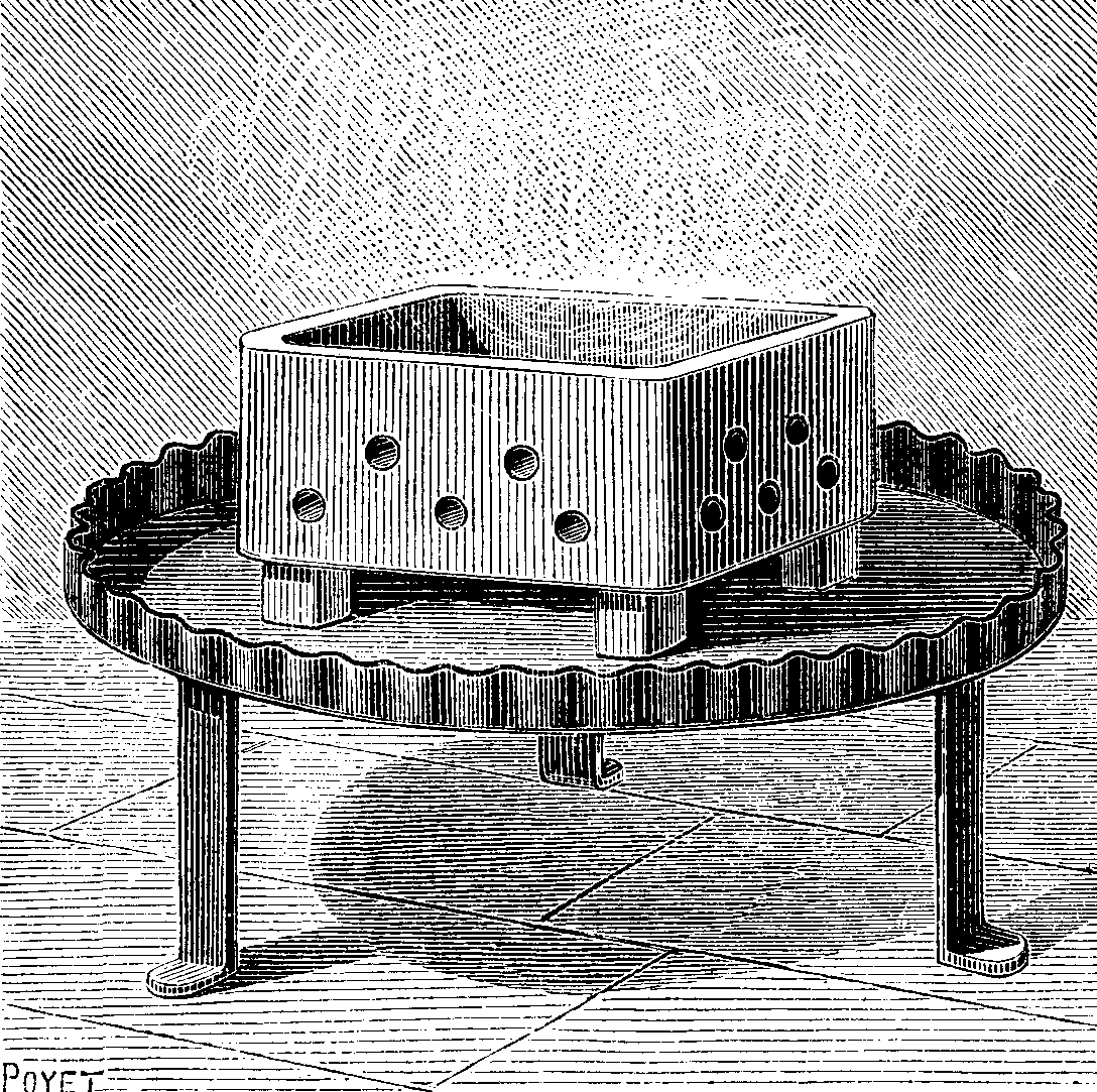
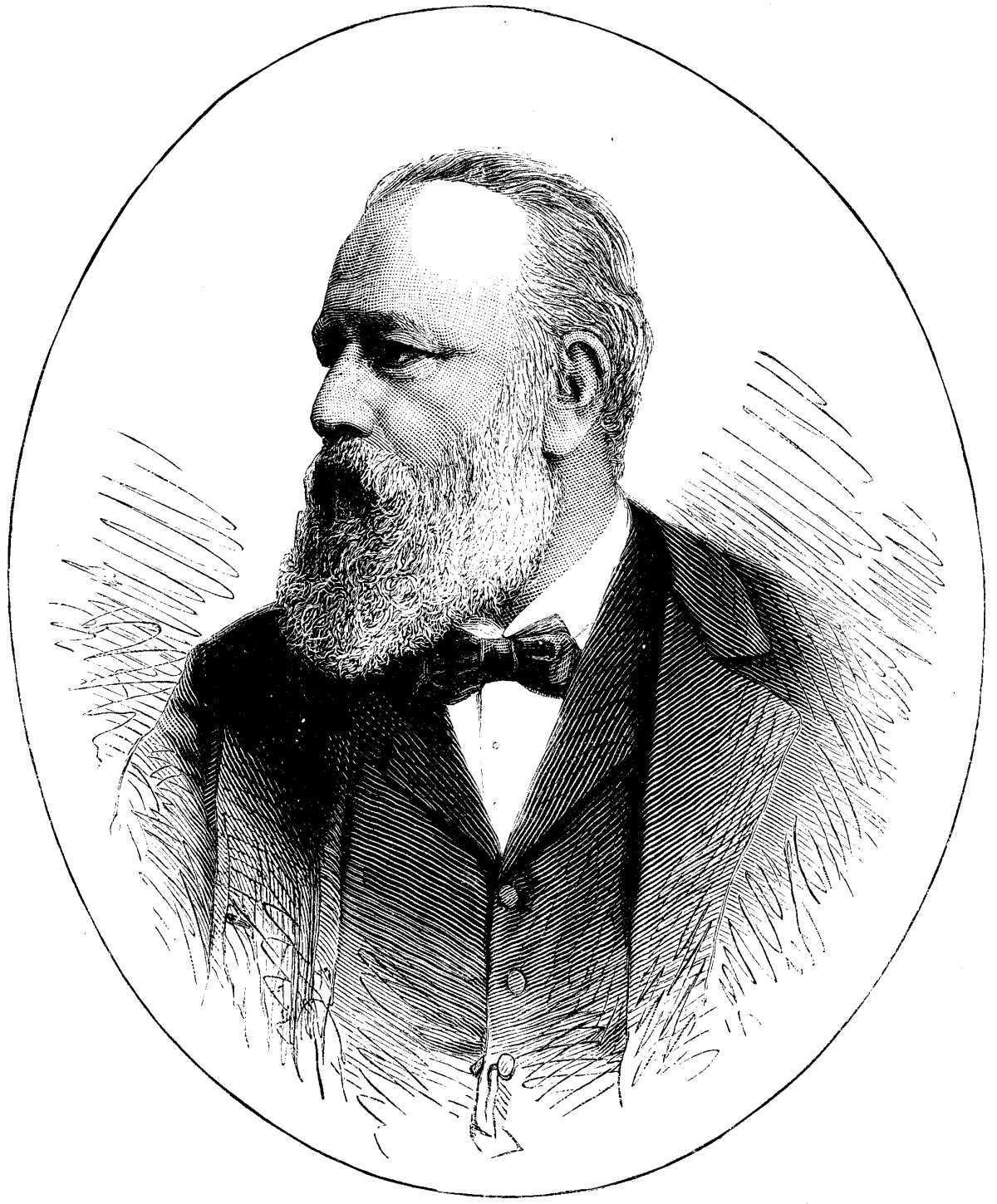
FIG. 1.—BURNER FOR SULPHUR.
The process by combustion of sulphur is the simplest and cheapest. To effect such combustion, it suffices to place a piece of iron plate upon the floor of the room, and on this to place bricks connected with sand, or, what is better, to use a small refractory clay furnace (as advised by Mr. Pasteur), of oblong form, 8 inches in width by 10 in length, and having small apertures in the sides in order to quicken combustion.
In order to obtain a complete combustion of the flowers of sulphur, it is necessary to see to it that the burning is effected equally over its entire surface, this being easily brought about by moistening the sulphur with alcohol and then setting fire to the latter. Through the use of this process a complete and absolute combustion has been obtained of much as from 18 to 20 grains of sulphur per cubic foot.
In the proportion of 8 grains to the cubic foot, all the different culture broths under experiment were sterilized save the one containing the bacteria of charbon. As for the vaccine virus, its properties were destroyed. This economical process presents but two inconveniences, viz., the possibility of fire when the furnace is badly constructed, and the alteration of such metallic objects as may be in the room. In fact, the combustion of sulphur is attended with the projection of a few particles of the substance, which form a layer of metallic sulphide upon copper or iron objects.
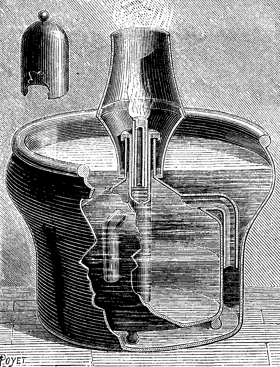
FIG. 2.—CKIANDI BEY'S APPARATUS FOR BURNING CARBON SULPHIDE.
The use of liquid sulphurous acid in siphons does not offer the same inconveniences. These siphons contain about one and a half pounds of sulphurous acid. The proportion necessary to effect the sterilization of the culture broths is one siphon per 706 cubic feet. In such a case the modus operandi is as follows: In the middle of the room is placed a vessel, which is connected with the exterior by means a rubber tube that passes through a hole in the door. After the door has been closed, it is only necessary to place the nozzle of the siphon in the rubber tube, and to press upon the lever of the siphon valve, to cause the liquid to pass from the siphon to the interior of the vessel. The evaporation of the liquid sulphurous acid proceeds very rapidly in the free air. This process is an exceedingly convenient one; it does away with danger from fire, and it leaves the gildings and metallic objects that chance to be in the room absolutely intact. Finally, the acid's power of penetration appears to be still greater than that which is obtained by the combustion of sulphur. It has but one drawback, and that is its high price. Each siphon is sold to the public at the price of one dollar. To municipalities using sulphurous acid in this form the price would be reduced to just one-half that figure.
It will be seen, then, that for a room of 3,530 cubic feet capacity the cost would be $5.00 or $2.50.
The combustion of sulphide of carbon furnishes an abundance of sulphurous acid, but has hitherto been attended with danger. This, however, has recently been overcome by the invention of a new burner by Mr. Ckiandi Bey. The general arrangement of this new apparatus is shown in Figs. 2 and 3.
Mr. Ckiandi's burner consists of an external vessel, A B C D. of tinned copper, containing a vessel, I H E F, to the sides of which are fixed three siphons, R, S.
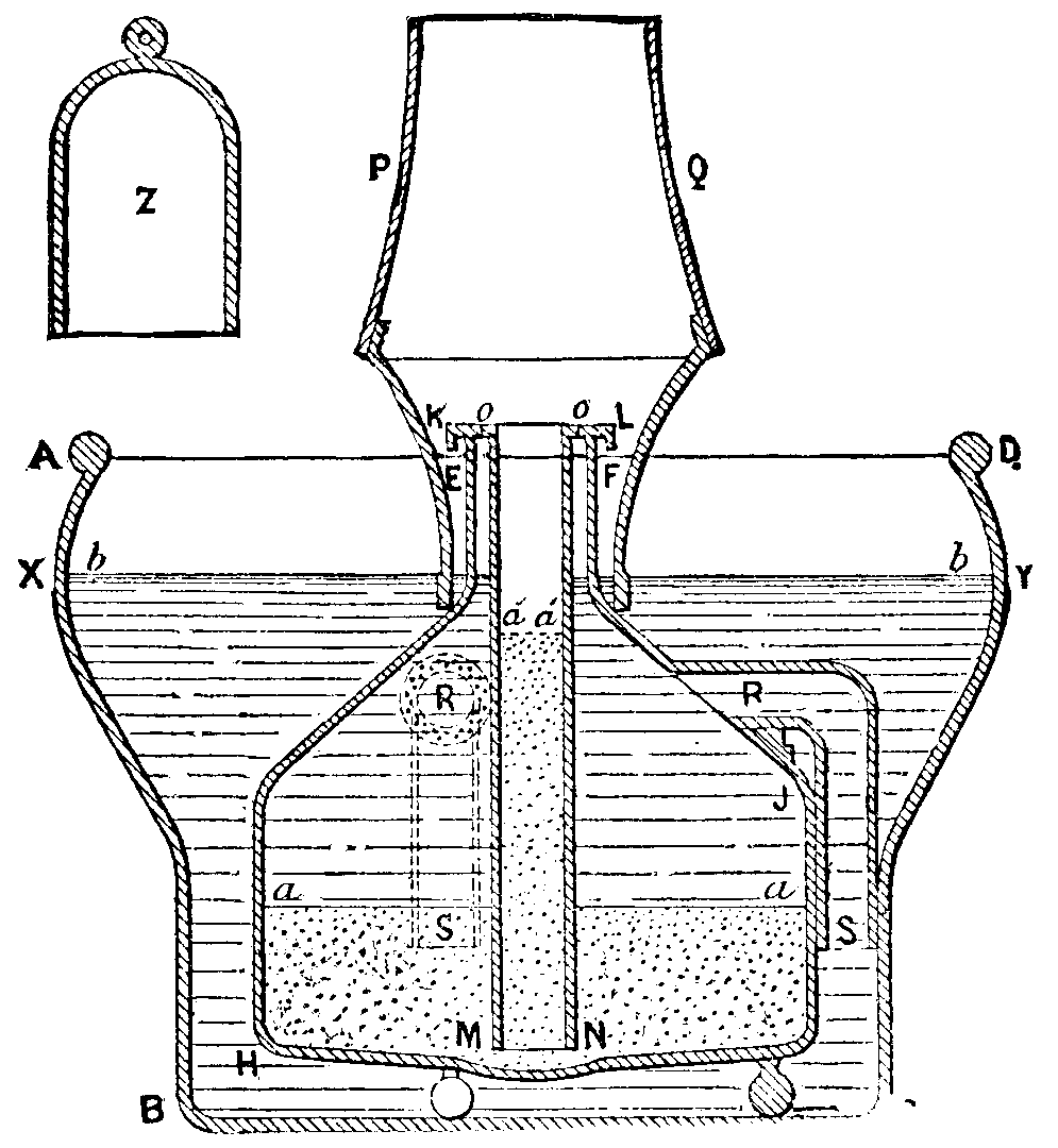
FIG. 3.—SECTION OF THE APPARATUS.
To operate the burner, we place the cylindrical tube, K L M N, in the inner vessel, and pour sulphide of carbon into it up to the level aa. This done, we fill the external vessel with water up to the level bb. Thanks to the siphons, the water enters the inner vessel, presses the sulphide of carbon, which is the heavier, and causes it to rise in the tube up to the level a'a', where it saturates a cotton wick, which is then lighted. The upper end of the tube is surmounted with a chimney, PQ. which quickens the draught.
The combustion may be retarded or quickened at will by causing the level bb of the water to rise or lower.
The burner is placed in the room to be disinfected, which, after the wick has been lighted, is closed hermetically. When all the sulphide is burned it is replaced by water, and the lamp goes out of itself.
The combustion proceeds with great regularity and without any danger. It takes about five and a half pounds for a room of 3,500 cubic feet capacity. The process is sure and quite economical, since sulphide of carbon is sold at about five cents per pound, which amounts to 25 cents for a room of 3,500 cubic feet capacity. The burner costs ten dollars, but may be used for an almost indefinite period.
The process of producing sulphurous acid by the combustion of sulphide of carbon is, as may be seen, very practical and advantageous. It does not affect metallic objects, and it furnishes a disinfecting gas continuously, slowly, and regularly.
Mr. Ckiandi's burner may also be applied in several industries. It is capable of rendering great services in the bleaching of silk and woolen goods, and it may also be used for bleaching sponges, straw hats, and a number of other objects.—La Nature.
In many instances the accurate determination of the amount of graphite present in a rock has proved a rather troublesome problem. The first thought which naturally suggests itself is to burn the graphite and weigh the carbonic acid produced; but in the case of the sample which led me to seek for another method, this way could not be employed, for the specimen had been taken from the surface, and was covered and penetrated by vegetable growths which could not be entirely removed mechanically. Add to this the fact of the presence of iron pyrites and the probable occurrence of carbonates in the rock, and it will be at once seen that no reliance could be placed on the results obtained by this suggested method.
As the problem thus resolved itself into finding a way by which all interfering substances could be destroyed without affecting the graphite, it at once occurred to me to try the effect of caustic potash. I melted a few pieces of potash in a silver crucible until it had stopped spitting and was in quiet fusion. I then transferred the weighed sample to the crucible, the melted potash in which readily wetted the graphite rock. The mass was then gently heated, and occasionally stirred with a piece of silver wire. The heat never need be much above the melting point of the potash, though toward the last I have been in the habit of raising the temperature slightly, to insure the complete decomposition of the melt. When the decomposition is complete, which can be known by the complete absence of gritty particles, the crucible is cooled and then soaked out in cold water. This is very quickly accomplished, and we then see that we have an insoluble residue of graphite and a flocculent precipitate of lime, magnesia, iron hydrate, etc., while the organic matters have disappeared. The sulphides of iron, etc., have given up their sulphur to the potash, and everything except the graphite has suffered some change. The solution is now filtered through a weighed Gooch crucible, the residue washed a few times with water, and then treated with dilute hydrochloric acid (followed by ammonia to remove any silver taken up from the crucible), which will dissolve all the constituents of the residue except the graphite, and after washing will leave the latter free and in a condition of great purity.
As evidence of the accuracy of the method, I subjoin the results I obtained on a sample whose gangue was free from all organic and other impurities, consisting chiefly of quartz:
New Method.       Combustion in Oxygen, Weighing CO₂.
  15.51                         15.54
It is plain that such a result leaves nothing to be desired for the accuracy of the method, while, as regards time and trouble, the advantage lies on the side of the new method. I have completed a determination in less than two hours from the start, and did not hurry myself over it in any degree.
Fine pulverization of the sample is not essential, and in fact is rather detrimental, as the graphite, when fine, is more difficult to wash without loss. When operating on a coarse sample more time is necessarily taken, but the resulting graphite shows the manner of occurrence better, whether in scales or in the amorphous form.
In consulting the literature bearing on the subject, I cannot find any mention of this method employed as an analytical process; it has, however, been previously described as a commercial method for the purification of graphite,1 and I understand has been tried on a small scale in this country. The method, though inexpensive, yet seems to have been abandoned for some reason, and I am not aware that it is now employed anywhere.—Sch. Mines Quarterly.
[1]The elements of cyanogen, combined with sulphur, form a salt radical, sulphocyanogen, C2NS2, which is expressed by the symbol Csy. The sulphocyanide of potassium, KCsy, is prepared by fusing ferrocyanide of potassium, deprived of its water of crystallization, intimately mixed with half its weight of sulphur and 17 parts of carbonate of potassa. The molten mass, after having cooled, is exhausted with water, the solution evaporated to dryness, and extracted with alcohol, from which the crystals of the salt are separated by evaporation.
It is also made by melting the ferrocyanide of potassium with sulphide of potassium. It is a white, crystallizable salt of a taste resembling that of niter, soluble in water and alcohol, and extremely poisonous. It dissolves the chlorides, iodides, and bromides of silver, is, therefore, a fixing agent, but has not come in general use as such. Vogel speaks highly of it as an addition to the positive toning bath, although he prefers the analogous ammonium salt in the following formula:
Chloride of gold solution.... (1:50) 3 c. cm. (46-1/5 grains).
Sulphocyanide of ammonium ... 20 grammes (308 grains).
Water........100 c. cm. (3 ounces 5 drachms 40 grains).
Ferrocyanide of Potassium—K2Cfy+3HO, or K2C8N3Fe+3HO, is generally known by the name of yellow prussiate of potassa. It contains ferrocyanogen, a compound radical, consisting of 1 eq. of metallic iron and 3 eq. of the elements of cyanogen, and is designated by the symbol Cfy.
The potassium salt is manufactured on a large scale from refuse animal matter, as old leather, chips of horn, woolen rags, hoofs, blood (hence its German name, "Blutlaugen salz"), greaves, and other substances rich in nitrogen, by fusing them with crude carbonate of potassa and iron scraps or filings to a red heat, the operation to go on in an iron pot or shell, with the exclusion of all air. Cyanide of potassium is generated in large quantities. The melted mass is afterward treated with hot water, which dissolves the cyanide and other salts, the cyanide being then quickly converted by the action of oxide of iron, formed during the operation of fusing, into ferrocyanide. The filtered solution is evaporated, crystallized, and recrystallized. The best temperature for making the solution is between 158 and 176 deg. F. The conversion of the cyanide into the ferrocyanide is greatly facilitated by the presence of finely divided sulphuret of iron and caustic potash. Some years ago this salt was manufactured by a process which dispensed with the use of animal matter, the necessary nitrogen being obtained by a current of atmospheric air. Fragments of charcoal, impregnated with carbonate of potassa, were exposed to a white heat in a clay cylinder, through which a current of air was drawn by a suction pump. The process succeeded in a chemical sense, but failed on the score of economy.
Richard Brunquell passes ammonia through tubes filled with charcoal, and heated to redness so as to form cyanide of ammonium, which is converted into the ferrocyanide of potassium by contact with potash solution and suitable iron compounds. Ferrocyanide of potassium is in large beautiful transparent four-sided tabular crystals, of a lemon-yellow color, soluble in four parts of cold and two of boiling water, insoluble in alcohol. Exposed to heat it loses three eq. of water, and becomes anhydrous; at a high temperature it yields cyanide of potassium, carbide of iron, and various gases. This salt is said to have no poisonous properties, although the dangerous hydrocyanic acid is made from it. In large doses it occasions, however, vertigo, numbness, and coldness. It is used in various photographic processes. Newton employs it in combination with pyrogallol and soda in the development of bromo-gelatine plates.
The ferri or ferrid cyanide of potassium discovered by Gmelin is often, but improperly, termed red prussiate of potash. It is formed by passing a current of chlorine gas through a solution of ferrocyanide of potassium until the liquid ceases to give a precipitate with a salt of sesquioxide of iron, and acquires a deep, reddish-green color. The solution is then evaporated, crystallized, and recrystallized. It forms regular prismatic or tabular crystals, of a beautiful ruby-red tint, permanent in the air, soluble in four parts of cold water. The crystals burn when introduced into the flame of a candle, and emit sparks.
The theory of the formation of this salt is, that one eq. of chlorine withdraws from two eq. of the ferrocyanide of potassium, one eq. of potassium, forming chloride of potassium, which remains in the mother liquid. The reaction is explained by the following equation: 2(K2Cfy)+Cl=K3Cfy2+KCl.
The radical ferridcyanogen, isomeric2 with ferrocyanogen, is supposed to be formed by the coalescence of two equivalents of ferrocyanogen, and is represented by the symbol Cfdy; accordingly the formula of ferridcyanide of potassium is K3Cfdy.
Ferridcyanide of potassium has found extensive application in photographic processes for intensifying negatives; those of Eder, in combination with nitrate of lead, or Selle's, with nitrate of uranium; Ander's blue intensification of gelatine negatives, Farmer's process of reducing intensity, the coloring of diapositives, the very important blue printing, and various others, are daily practiced in our laboratories.
The ferrocyanide of potassium is a chemical reagent of great value, giving rise to precipitates with the neutral or slightly acid solutions of metals, like the beautiful brown ferrocyanide of copper, and that of lead. When a ferrocyanide is added to a solution of a sesquioxide of iron, Prussian blue or ferrocyanide of iron is produced. The exact composition of this remarkable substance is not distinctly stated, as various blue compounds may be precipitated under different circumstances. Berzelius gives the following account: 3 eq. of ferrocyanide and 2 eq. of sesquioxide of iron are mutually decomposed, forming 1 eq. of Prussian blue and 6 eq. of the potassa salt, which remains in solution, or 3K2Cfy + 2(Fe2O33NO3) = Fe4Cfy3 + 6(KO,NO5). It forms a bulky precipitate of an intense blue, is quite insoluble in water or weak acids, with the exception of oxalic acid, with which it gives a deep blue liquid, occasionally used as blue ink.
Ferridcyanide of potassium, added to a salt of the sesquioxide of iron, yields no precipitate, but merely darkens the reddish-brown solution; with protoxide of iron it gives a blue precipitate, containing Fe3Cfdy, which is of a brighter tint than that of Prussian blue, and is known by the name of Turnbull's blue. Hence, the ferridcyanide of potassium is as excellent a test for protoxide of iron as the yellow ferrocyanide is for the sesquioxide.—E., Photo. Times.
[2]The illuminating gas and hydrogen apparatus, illustrated herewith, is adapted to all cases in which it is desirable to manufacture gas upon a small scale.
Through the use solely of oil or water, it produces illuminating gas or pure hydrogen for all the applications that may be required of them. It consists of three parts, viz., of a vaporizer, A, which converts the liquids into gas; of a distributer, B, which contains and distributes the liquids to be converted into gas, and of a regulator, C, which automatically regulates the flow of the liquids in proportion as they are used.
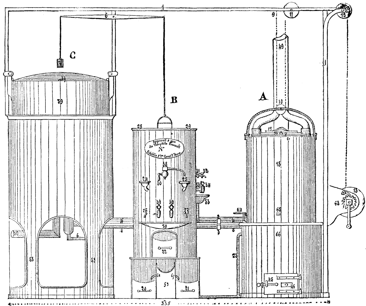
FIG. 1.—FOUCAULT'S GAS APPARATUS.
In the vaporizer Mr. Foucault, the inventor of the apparatus, obtains a perfectly regular combustion through the use of a central column, 15, charged with fuel, closed at the upper part, open beneath, and entering a furnace that is fed by it with regularity, the zone of combustion not being able to extend beyond the level of the draught. The grate, 16, is capable of revolving upon its axis in order to separate the cinders. It also oscillates, and is provided with jaws for crushing the fuel; and it may likewise be lowered so as to let the fire drop into the ash-pan when it is desired to stop operations.
The vaporizer, properly so called, is not placed directly over the fire, and for this reason the production of a spheroidal state of the liquid is avoided. It consists of a vessel, 44, into which the liquid is led by a pipe, 43. The cast-iron evaporating vessel, 14, is provided with appendages, 14 bis, which dip into the liquid and bring about its evaporation. A refractory clay sleeve, 41, protects the lower part of the cylinder, 15, from the fire, and diminishes the smoke passages at 42. The vapor produced makes its way vertically through a layer of charcoal placed between the evaporating vessel, 14, and the receiver, 17, and serving to decompose the aqueous vapor formed.
All clay and red and white lead joints are done away with in this part of the apparatus, as are also packing bolts. Thus, at the upper part the cover, 19, is provided with a rim that enters a cavity filled with lead, so, too, the lower part of the evaporating vessel, 14, rests in a channel containing lead. There is also at 30, a joint of the same character for the rim of the external cylindrical vessel, 18. Both this latter and the receiver, 17, dip beneath into a tank of water, 66.
The distributer, B, is so arranged as to cause the water, and oil, and the liquids to be vaporized to flow with the greatest regularity, and proportionally to the consumption of the gas in cases where the latter is not stored up in a gas meter. The flow is controlled by cocks that are actuated by variations in the height of the regulator receiver. All the condensation that occurs in the various parts of the apparatus collects in a receptacle, 52, so arranged as to perform the office of a separator and set apart the oil at 20, and the water at 21, through the natural effect of their difference in density. This latter is likewise utilized for causing the oil to flow into the vaporizer through 26 and 27, instead of using a graduated cock that receives a variable pressure from the receiver. In this way every cause of obstruction is avoided.
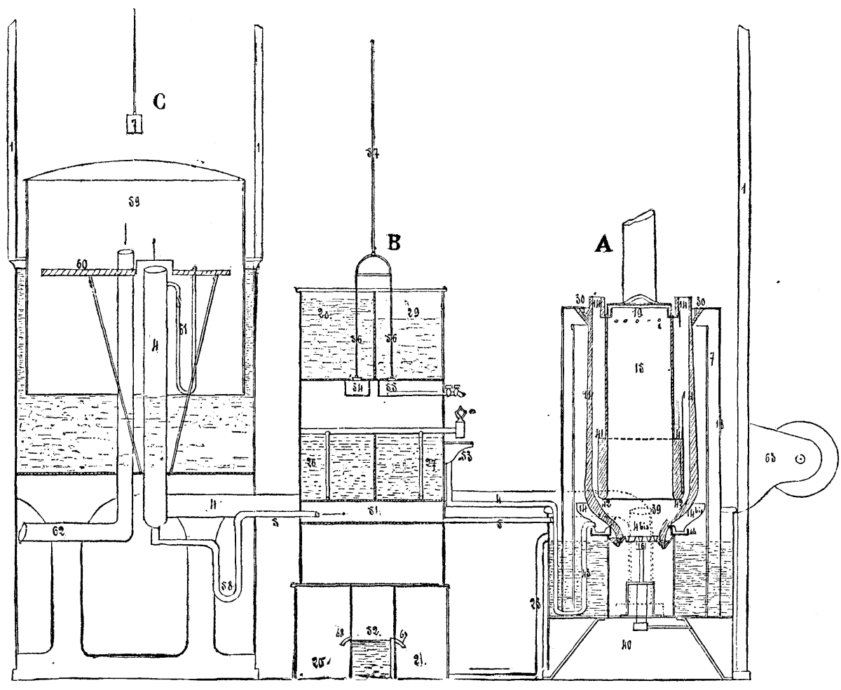
FIG. 2.—SECTION.
We have stated that the regulator, C, serves to automatically regulate the flow of the liquids proportionally to the consumption of the gases produced. To effect this a communication is established between the regulator receiver, 59, and the aperture through which the liquids flow, and the flow is thus modified by the valves, 54 and 55.
The water contained in the reservoir of the regulator serves to wash the gas which enters through a number of orifices in the disk, 60, this latter being fixed beneath the level of the water. The gas may be purified by dissolving metallic salts in the water.
By means of the arrangement above described, there may be manufactured at will a rich gas from liquid hydrocarburets, hydrogen from water, and gas obtained by an admixture of two others simultaneously produced and combined in the apparatus.—Chronique Industrielle.
A new explosive has been discovered by M. Roca, a French engineer, who communicates an account of it to Le Génie Civil. The discovery was due entirely to scientific induction from some experiments made upon different specimens of dynamite, with a view to the determination of the effect on the explosive force of the various inert or at least slowly combustible substances with which nitro-glycerine is mixed to produce the dynamite of commerce. Of late, in place of the infusorial earth which formed the solid portion of Nobel's dynamite, such substances as sawdust, powdered bark, and even gunpowder, have been used, probably for the sake of economy alone, without, except in the latter case, any reference to the influence which they might have upon the combustion of the nitro-glycerine; but M. Roca, in testing a variety of samples, was struck by the difference among them in regard to energy of explosion, and discovered that if a portion of free carbon, sufficient to combine with the oxygen disengaged from the nitro-glycerine, was present at the moment of detonation, the effect was greater than where, as in the case of gunpowder, the solid portion alone furnished oxygen enough to burn all the free carbon, without calling upon the nitro-glycerine for any. In fact, it appeared from experiment that the dose of carbon might with advantage be so great as not only to be itself oxidized into carbonic oxide by the oxygen of the nitro-glycerine, but to reduce the carbonic acid developed by the explosion of the latter itself into carbonic oxide. The limit of the advantageous effect of free carbon ceased here, and if more were added to the mixture, the cavities formed by the explosion in the lead cubes used for test were found simply lined with soot; but up to the limit necessary for converting all the carbon in the dynamite into carbonic oxide, the addition of a reducing agent was shown to be an important gain. This was confirmed by theory, which shows that pure nitro-glycerine, which is composed of six parts of carbon and two of hydrogen, combined with three times as much nitric acid and water, decomposes on explosion into six parts of carbonic acid, five of watery vapor, one of oxygen, and three of nitrogen, while the addition of seven more parts of free carbon to the mixture causes the development, by explosion, of thirteen volumes of carbonic oxide, five parts of watery vapor, and three of nitrogen, or twenty-one volumes of gas in place of fifteen. As the power of an explosive depends principally on the amount of gas which results from its sudden combustion, it was evident that the addition of pure or nearly pure carbon, in a condition to be readily combined with the other elements, ought to increase materially the force of nitro-glycerine, and M. Roca experimented accordingly with an admixture of sugar, as a highly carbonized body immediately available, and found that three parts of this, mixed with seven parts of nitro-glycerine, detonated with a force from thirty to thirty-five per cent. greater than that of pure nitro-glycerine. Many other organic carbonaceous substances may be employed in place of sugar, with various advantages. In comparing these simple compounds with the celebrated explosive gum, prepared by dissolving gun-cotton in nitro-glycerine, it is found that the latter is far inferior, having an energy very little superior to that of pure nitro-glycerine.
This little apparatus, invented by Prof. Mora, of Senlis, permits of dividing circumferences or circles into equal or proportional parts. It consists (Fig. 2) of a rule, A, divided into equal or proportional parts, which pivots in the manner of a compass around a rod, T, that serves as a central rotary point. Along this rule moves a slide, R, provided with an aperture, C, which is made to coincide with one of the divisions. This division corresponds to the number of equal or proportional parts into which the circle is to be divided. The slide is provided with a wheel, E, that carries a point which serves at every revolution to trace the points that indicate the divisions of the circumference.
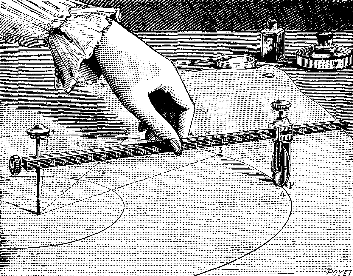
FIG. 1.—MODE OF USING THE CIRCLE DIVIDER.
The apparatus operates as follows: Suppose, for example, that it becomes necessary to divide a circumference into 19 equal parts: We make the aperture, C, coincide with the 19th division of the rule, and fix the point of the rod, T, in the center of the circumference, and cause the rule to revolve around it. The wheel, E, will revolve upon its axis, g, and, at every revolution, its point will make a mark which corresponds to the 19th part of the circumference—
Circumf. c / Circumf. C = r / R
It is always necessary that the extremity of the wheel, E, and the center-point, T, shall be at the same height in order to have the divisions very accurate.
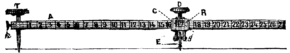
FIG. 2.—THE CIRCLE DIVIDER.
Although the manufacture of soluble glass does not strictly belong to the glass maker's art, yet it is an allied process to that of manufacturing glass. Of late soluble glass has been used with good effect as a preservative coating for stones, a fire-proofing solution for wood and textile fabrics. Very thin gauze dipped in a solution of silicate of potash diluted with water, and dried, burns without flame, blackens, and carbonizes as if it were heated in a retort without contact of air. As a fire-proofing material it would be excellent were it not that the alkaline reaction of this glass very often changes the coloring matters of paintings and textile fabrics. Since soluble glass always remains somewhat deliquescent, even though the fabrics may have been thoroughly dried, the moisture of the atmosphere is attracted, and the goods remain damp. This is the reason why its use has been abandoned for preserving theater decorations and wearing apparel. Another application of soluble glass has been made by surgeons for forming a protecting coat of silicate around broken limbs as a substitute for plaster, starch, or dextrine.
The only use where soluble glass has met with success is in the preservation of porous stones, building materials, paintings in distemper, and painting on glass. Before we describe these applications, we will give the processes used in making soluble glass.
The following ingredients are heated in a reverberatory furnace until fusion becomes quieted: 1,260 pounds white sand, 660 pounds potash of 78°. This will produce 1,690 pounds of transparent, homogeneous glass, with a slight tinge of amber. This glass is but little soluble in hot water. To dissolve it, the broken fragments are introduced into a iron digester charged with a sufficient quantity of water, at a high pressure, to make a solution marking 33° to 35° Baume. Distilled or rain water should be used, as the calcareous salts contained in ordinary water would produce insoluble salts of lime, which would render the solution turbid and opalescent; this solution contains silica and potash combined together in the proportion of 70 to 30.
Silicate of soda is made with 180 parts of sand, 100 parts carbonate of soda (0.91), and is to be melted in the same manner as indicated previously.
Soluble glass may also be prepared by the following method: A mixture of sand with a solution of caustic potash or soda is introduced into an iron boiler, under 5 or 6 atmospheres of pressure, and heated for a few hours. The iron boiler contains an agitator, which is occasionally operated during the melting. The liquid is allowed to cool until it reaches 212°, and is drawn out after it has been allowed to clear by settling; it is then concentrated until it reaches a density of 1.25, or it may be evaporated to dryness in an iron kettle. The metal is not affected by alkaline liquors.
The glass is soluble in boiling water; cold water dissolves but little of it. The solution is decomposed by all acids, even by carbonic acid. Soluble glass is apparently coagulated by the addition of an alkaline salt; mixed with powdered matters upon which alkalies have no effect, it becomes sticky and agglutinative, a sort of mineral glue.
To apply soluble glass for the preservation of buildings and monuments of porous materials, take a solution of silicate of potash of 35° Baume, dilute it with twice its weight of water, paint with a brush, or inject with a pump; give several coats. Experience has shown that three coats applied on three successive days are sufficient to preserve the materials indefinitely, at a cost of about 15 cents per square yard. When applied upon old materials, it is necessary to wash them thoroughly with water. The degree of concentration of the solutions to be used varies with the materials. For hard stones, such as sand and free stones, rock, etc., the solution should mark 7° to 9° Baume; for soft stones with coarse grit, 5° to 7°; for calcareous stones of soft texture, 6° to 7°. The last coating should always be applied with a more dilute solution of 3° to 4° only.
Authorities are divided upon the successful results of the preservation of stone by silicates. Some claim in the affirmative that the protection is permanent, while others assert that with time and the humidity of the atmosphere the beneficial effects gradually disappear. It might be worth while to experiment upon some of the porous sandstones, which, under the extreme influence of our climate, rapidly deteriorate; such, for instance, as the Connecticut sandstone, so popular at one time as a building material, but which is now generally discarded, owing to its tendency to crumble to pieces when exposed to the weather even for a few years.
Soluble glass has also been used in Germany to a great extent for mural painting, known as stereochromy. The process consists in first laying a ground with a lime water; when this is thoroughly dry, it is soaked with a solution of silicate of soda. When this has completely solidified, the upper coating is applied to the thickness of about one-sixteenth of an inch, and should be put on very evenly. It is then rubbed with fine sandstone to roughen the surface. When thoroughly dry, the colors are applied with water; the wall is also frequently sprinkled with water. The colors are now set by using a mixture of silicate of potash completely saturated with silica, with a basic silicate of soda (a flint liquor with soda base, obtained by melting 2 parts sand with 3 parts of carbonate of soda). As the colors applied do not stand the action of the brush, the soluble glass is projected against the wall by means of a spray. After a few days the walls should be washed with alcohol to remove the dust and alkali liberated.
The colors used for this style of painting are zinc white, green oxide of chrome, cobalt green, chromate of lead, colcothar, ochers, and ultramarine.
Soluble glass has also been used in the manufacture of soaps made with palm and cocoanut oil; this body renders them more alkaline and harder.
Interesting experiments have been made with soluble glass for coloring corals and shells. By plunging silicated shells into hot solutions of salts of chrome, nickel, cobalt, or copper, beautiful dyes in yellow, green, and blue are produced. Here seems to be a field for further application of this discovery.
Soluble glass has also been applied to painting on glass in imitation of glass staining. By using sulphate of baryta, ultramarine, oxide of chrome, etc., mixed with silicate of potash, fast colors are obtained similar to the semi-transparent colors of painted windows. By this means a variety of cheap painted glass may be made. Should these colors be fired in a furnace, enameled surfaces would be produced. As a substitute for albumen for fixing colors in calico printing, soluble glass has been used with a certain degree of success; also as a sizing for thread previous to weaving textile fabrics. Thus it would seem that this substance has been used for many purposes, but since its application does not seem to have been extended to any great degree, the defects here pointed out in its use as a fire-proofing material perhaps also exist, to a certain degree, in its other applications. In painting upon glass, for instance, it is asserted that the brilliancy and finish of ordinary vitrified colors cannot be obtained.—Glassware Reporter.
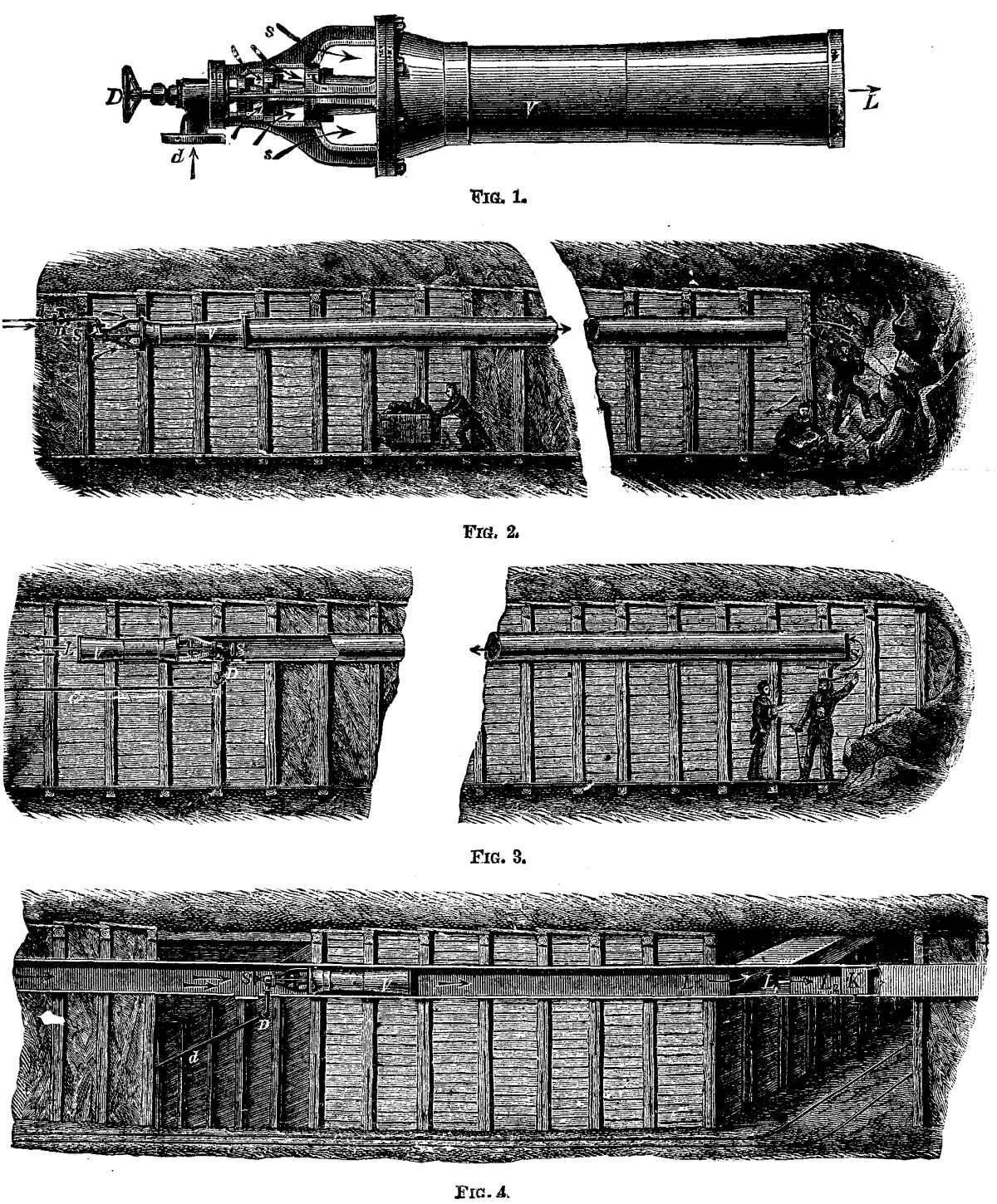
KORTING'S JET VENTILATOR.
Messrs. Korting bros., of London, induced by the interest that has been directed to the separate ventilation of mines in which fire-damp is apt to form, have adopted for this purpose their jet ventilator. The instrument, which we illustrate in Fig. 1, has been, we understand, considerable simplified, and adapted for the special object in view. The ventilators are worked by compressed air, and are so arranged that, without stopping their action, the quantity of air they deliver can be rapidly increased or diminished. This ample power of control has been arranged for by the special wish of the mining authorities, who wish to regulate the ventilation according to the development of fire-damp or the greater or less number of men at work. Under circumstances of this kind the quantity of air taken into the mine can be changed instantly. The illustrations, Figs. 2, 3, and 4, show different modes of fixing the jet ventilator. In Fig. 2, it is arranged to blow the air forward; in Fig. 3, it is shown exhausting the air; and in Fig. 4, it is represented as exhausting and blowing simultaneously, the efficiency in each case being always the same. Any bends in the conduit affect the result to a very slight degree, and the ventilator may be used with advantage when the conduit is divided as in Fig. 4, in order to get the fresh air to different points. The ventilators are easily fixed to the air conduits. If they are to be connected to zinc air pipes, the pipe is simply slipped over the point, L. in Fig. 1, and if to wooden conduits the apparatus is simply put into them, and if no other support is required. Furthermore, they are so light that it suffices for one man to fix them or change their position.
Messrs. Korting Bros. advance the following claims for this mode of ventilating mines: Certainty of action, no moving parts whatever, and, consequently, no need of lubrication; no need of attention.--Mech. World.
From trials conducted by Ledebur, it appears that cast iron is rendered suitable for foundry purposes—i.e., to fill the moulds well and to yield sharp and definite forms free of flaws, to be cut with a chisel, and turned on a lathe—through a certain percentage of graphite, whose presence depends on that of carbon and silicium. Cast iron free of silicium yields on cooling the entire amount of carbon in the amorphous state, while presence of the former metal gives rise to the formation of graphite, and, consequently, causes a partial separation of carbon. Iron suffers on casting loss of graphite, assumes a finely-grained texture, becomes hard and brittle, and is changed from gray to white. In view of the fact that samples of cast iron with equal percentage of silicium and carbon yield on casting a different product, it has become necessary to institute experiments as to the cause of this behavior. Samples of cast iron were therefore repeatedly melted, and thin sections of each melt examined; these sections exhibited a gray color, though less apparent than in the unmelted sample, and possessed sufficient softness to admit boring and filing. During these processes of fusing, the amount of silicium, carbon, and manganese had been gradually decreased, and amounted to 12.7, 17.6, and 24.4 per centum for silicium in the three samples examined. It also was observed that the more manganese the iron contains the less readily the percentage of silicium is diminished; and since manganese is more subject to oxidation than silicium, it is capable to reduce silicic acid of the slag or lining to metal, and thus to augment the amount of silicium in cast iron. The percentage of carbon also suffers diminution by oxidation, which latter process is impeded by presence of manganese, a fact of some importance in melting of cast iron in the cupola furnace. An excess of manganese renders cast iron hard and brittle, and imparts to it the properties to absorb gases, while an amount of 1.5 per centum, as found in Scotch iron, undoubtedly has the effect to produce those properties for which this iron is held in high repute. The amount of copper is not visibly altered by fusion, but that of phosphorus and sulphur slowly increased.
Experiments in regard to the relation between chemical composition and strength of the material have established that a large amount of silicium, graphite, manganese, and combined carbon reduce the elasticity, strength, and tenacity of cast iron, and that a limited percentage of silicium counteracts the injurious influence produced by an excess of combined carbon. On remelting of cast iron, increase in tensile strength was observed, which attained its maximum in iron with a small percentage of silicium after the third, and in such with a large amount after the fourth melting. The increase in tensile strength was accompanied by a loss of silicium, graphite, and manganese coupled with a simultaneous augmentation of combined carbon. A fifth melting of the cast iron renders it hard, brittle, and white, through oxidation of silicium and subsequent lowering of the amount of carbon. On lessening the percentage of combined carbon with formation of graphite the injurious influence of the accessorial constituents of cast iron is diminished, especially that produced by the presence of phosphorus.—Eisenhuettentechnik.
One of the most important things to be considered in boiler construction is the position and arrangement of the feed apparatus, but it is, unfortunately, one of the elements that is most often overlooked, or, if considered at all, only in a very superficial manner. Many seem to think that it is only necessary to have a hole somewhere in the boiler—no matter what part—through which water may be pumped, and we have all that is desired. This is a very grave error. Many boilers have been ruined, and (we make the assertion with the confidence born of long experience) a large number of destructive explosions have been directly caused by introducing the feed water into boilers at the wrong point.
On the location and construction of the feed depends to some extent the economical working of a boiler, and, to a great extent, especially with certain types of boilers, its safety, durability, and freedom from a variety of defects, such as leaky seams, fractured plates, and others of a similar kind. And it is unfortunately true that the type of boiler which from its nature is most severely affected by mal-construction, such as we are now speaking of, is the very one which is the oftenest subject to it. We are speaking now more particularly of the plain cylinder boiler, of which there are many in use throughout the country.
Plain cylinder boilers are, as a rule, provided with mud drums located near the back end. As a rule, also, these boilers are set in pairs over a single furnace, and the mud drum extends across beneath, and is connected to both, and one end projects through the setting wall at the side. Our illustrations show a typical arrangement of this kind. Fig. 1 shows a transverse section of the boilers and setting, while Fig. 2 shows a longitudinal section of the same. It is a favorite method to connect the feed pipe, F, to the end of the mud drum which projects through the wall, and here the feed water is introduced, whether hot or cold; and there is really not so much difference after all between the two, for no matter how effective a heater may be, the temperature to which it can raise water passing through is quite low compared with the temperature of the water in the boiler due to a steam pressure of say eighty pounds per square inch. The difference in the effect produced by feeding hot or cold water at the wrong place is one of degree, not of kind.
When a boiler is under steam of say eighty pounds per square inch, the body of water in it will have a temperature of about 324 degrees Fahr., and the shell plates will necessarily be somewhat hotter, especially on the bottom (just how much hotter will depend entirely upon the quantity of scale or sediment present). Now introduce a large volume of cold water through an opening in the bottom, and what becomes of it? Does it rise at once, and become mixed with the large body of water in the boiler? By no means. It cannot rise until it has become heated, for there is a great difference between the specific gravity of water at 60°, or even 212° Fahr., and water at 324°. Consequently, it "hugs" the bottom of the boiler, and flows toward the front end, or hottest portion of the shell. Now let us examine the effect which it produces.
We know that wrought iron expands or contracts about 1 part in 150,000 for each degree that its temperature is raised or lowered. This is equivalent to a stress of one ton per square inch of section for every 15 degrees. That is, suppose we fix a piece of iron, a strip of boilerplate, for instance, ¼ of an inch thick and 4 inches wide, at a temperature of 92 degrees Fahr., between a pair of immovable clamps. Then, if we reduce the temperature of the bar under experiment to that of melting ice, we put a stress of four tons upon it, or one ton for each inch of its width.
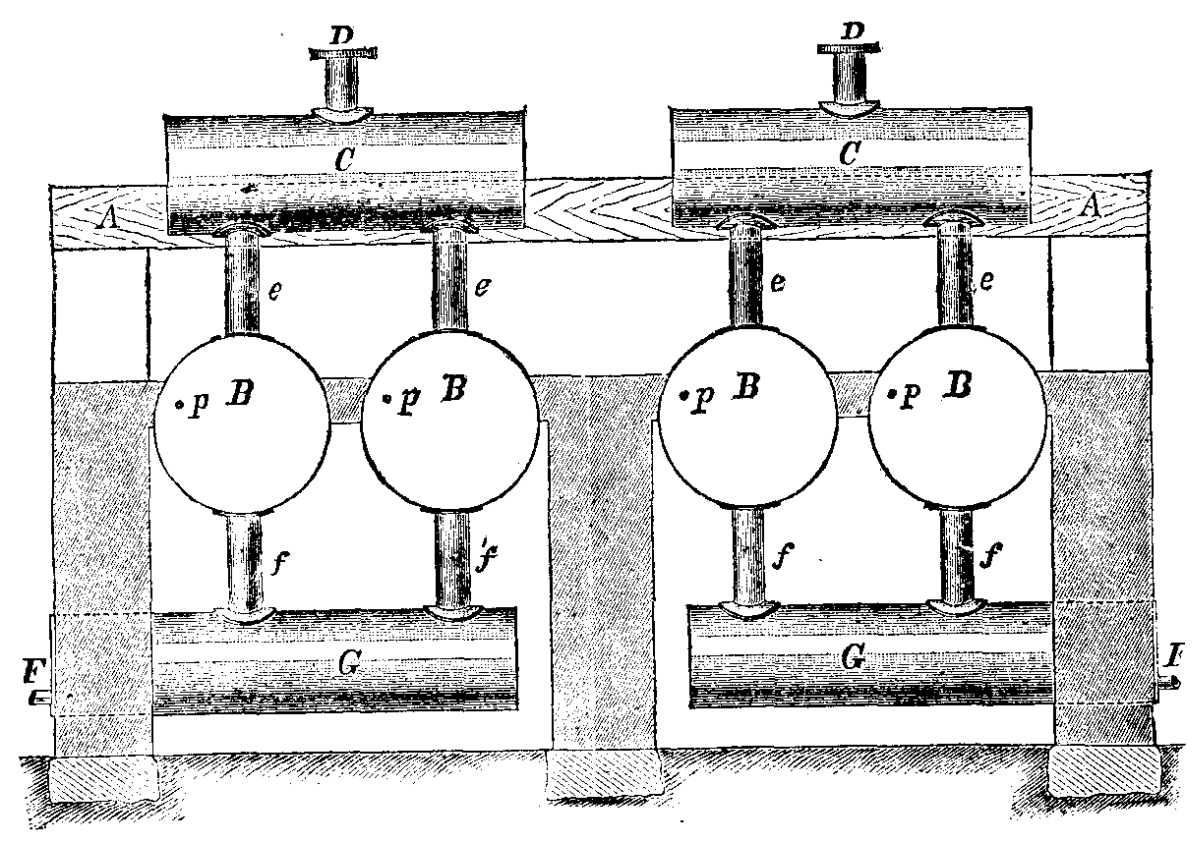
FIG. 1
Now this is precisely what happens when cold water is fed into the bottom of a boiler. We have the plates of the shell at a temperature of not less, probably, than 350° Fahr. A large quantity of cold water, often at a temperature as low as 50° Fahr., is introduced through an opening in the bottom, and flows along over these heated plates. If it could produce its full effect at once, the contraction caused thereby would bring a stress of 300 ÷ 15 = 20 tons per square inch upon the bottom plates of the shell. But fortunately it cannot exert its full effect at once, but it can act to such an extent that we have known it to rupture the plates of a new boiler through the seams on the bottom no less than three times in less than six weeks after the boilers were started up.
The effect in such cases will always be the most marked, especially if the plant is furnished with a heater, when the engine is not running, for then, as no steam is being drawn from the boilers, there is comparatively little circulation going on in the water in the boiler, and the water pumped in, colder than usual from the fact that the heater is not in operation, spreads out in a thin layer on the lowest point of the shell, and stays there, and keeps the temperature of the shell down, owing to the fires being banked or the draught shut, while the larger body of water above, at a temperature of from 300 to 325 degrees, keeps the upper portion of the shell at its higher temperature. It will readily be seen that the strain brought upon the seams along the bottom is something enormous, and we can understand why it is that many boilers of this class rupture their girth seams while being filled up for the night after the engine has been shut down. To most persons who have but a slight knowledge of the matter, we fancy it would be a surprise to see the persistence with which cold water will "hug" the bottom of a boiler under such circumstances. We have seen boilers when the fire has been drawn, and cold water pumped in to cool them off, so cold on the bottom that they felt cold to the touch, and must consequently have had a temperature considerably below 100° Fahr., while the water on top, above the tubes, was sufficiently hot to scald; and they will remain in such a condition for hours.
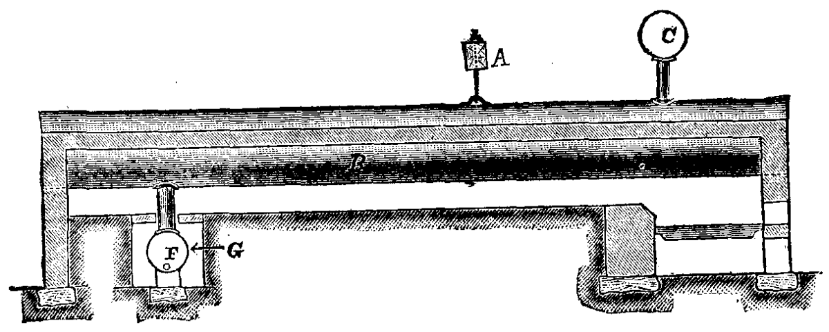
FIG. 2.
The only thing to be done, where feed connections are made in the manner described, is to change them, and by changing them at once much trouble, or even a disastrous explosion, may be avoided. Put the feedpipe in through the front head, at the point marked p in Fig. 1, drill and tap a hole the proper size for the feed pipe, cut a long thread on the end of the pipe, and screw the pipe through the head, letting it project through on the inside far enough to put on a coupling, then screw into the coupling a piece of pipe not less than eight or ten feet long, letting it run horizontally toward the back end of the boiler, the whole arrangement being only from 3 to 4 inches below the water line of the boiler, and hot or cold water may be fed indifferently, without fear of danger from ruptured plates or leaky seams. In short, put in a "top feed," and avoid further trouble.—The Locomotive.
Blue Prints.—The best formula for this process, of many that I have tried, is that furnished by Prof. C.H. Kain, of Camden, N.J., in which the quantity of ammonio-citrate of iron is exactly double that of the red prussiate of potash, and the solutions strong. This gives strong prints of a bright dark blue, and prints very quickly in clear sunlight.
Dissolve six grains of red prussiate of potash in one drm. of distilled water; in another drm. of distilled water dissolve twelve grains of ammonio-citrate of iron. Mix the two solutions in a cup or saucer, and at once brush over the surface of clean strong paper. Cover the surface thoroughly, but apply no more than the paper will take up at once; it should become limp and moist, but not wet. The above quantity of solution, two drms., will suffice to sensitize ten square feet of paper, or three sheets of the "regular" size of plain paper, 18×22. As fast as the sheets are washed over with the solution, hang them up to dry by one corner. The surplus fluid will collect in a drop at the lower corner, and can be blotted off.
Black Prints.—Wash the paper with a saturated solution of bichromate of potash, made quite acid with acetic acid. After printing, wash the prints in running water for twenty to thirty minutes, then float them face down on a weak solution (five to ten per cent.) of protosulphate of iron for five minutes, and wash as before. If preferred, the iron solution may be washed over the prints, or they may be immersed in it, but floating seems preferable. After the second washing, wash the prints over with a strong solution of pyrogallic acid, when the print will develop black, and the ground, if the washings were sufficient, will remain white. A final washing completes the process.
If a solution of yellow prussiate of potash be used in place of the pyro solution, a blue print is obtained. Bichromate prints can be made on albumenized paper by floating it on the solution, and by using a saturated solution of protosulphate of iron and a saturated solution of gallic acid. Very fine prints can be so produced nearly equal to silver prints, and at somewhat less cost, but with a little or no saving of time or labor.
Chief Proof Solution.—If old oxalate developer be exposed in a shallow vessel in a warm place, a deposit of light green crystals will be formed, composed of an impure oxalate of iron. If these crystals be dissolved in water, and paper washed with a strong solution, when dry it may be exposed in the printing-frame, giving full time. The image is very faint, but on washing in or floating on a moderately strong solution of red prussiate of potash for a minute or less, a blue positive is produced, which is washed in water as usual to fix it. The unused developer produces the best crystals for the purpose, and the pure ammonio-oxalate is vastly better than either.
All of the above operations, except the printing, should be carried on in the dark room, or by lamp or gas light only. The solutions and the paper should also be kept in the dark, and prepared as short a time as possible before use.
In photographing with the microscope, it frequently occurs that the operator, instead of devoting a negative to each of two or more similar objects for comparison, printing both upon the same print, prefers to have the whole series upon one negative, and taking from this a single print. There is often room for two or more images upon the same plate. If the center of the plate is devoted to one, obviously no more can be accommodated on it, but by placing one at each end, or one on each quarter of the plate, both economy of plates and convenience of printing are secured. The end may be readily accomplished by matting the plate as a negative is matted in printing.
Suppose it be desired to photograph four different species of acari on one plate, the image of each when magnified to the desired extent only covering about one-fourth the exposed area of the plate. First, a mat is prepared of card-board or thick non-actinic paper, which is adjusted to exactly fill the opening of the plate holder, lying in front of and close against the plate when exposed, and having one-quarter very exactly cut out. A convenient way to fit this mat is to leave projecting lugs on each side at exactly the same distance from the ends, and cut notches in the plate-holder into which the lugs may closely fit. If this work is carefully done, the mat may be reversed both sidewise and endwise, and the lugs will fit the notches; if so, it is ready for use. The object being focused upon the focusing glass or card, the camera is raised one-half the vertical dimension of the plate and displaced to one side half the horizontal dimension, when the image will be found to occupy one-quarter of the plate. The mat being placed in the plate holder, a focusing glass is inserted in the position the plate will occupy, and final adjustment and focusing made. The plate is then marked on one corner on the film side with a lead pencil, placed in the holder without disturbing the mat, and the exposure made. When the plate is replaced for a second exposure, either the mat is reversed or the plate turned end for end; but it is best to always place the plate in the holder in the same position and change the mat to expose successive quarters, but this requires the camera to be moved for each exposure.
With similar objects, and some judgment in making two exposures, negatives may be made with almost exactly the same density in each quarter, and by cutting out slightly less than one-quarter of the mat the four images will be separated by black lines in the print; by cutting out a trifle more than the exact quarter, they will be separated by white lines instead of black.
When the season for out-door work closes, amateurs begin to look about for means of employment during the dark evenings. There is, fortunately, no necessity for being idle, or to relinquish photographic pursuits entirely, even though the weather and light combine to render out-door work almost impracticable; and most amateurs will be found to have some hobby or favorite amusement which enables them to keep in practice during those months when many channels of employment are closed to them; and probably one of the most popular as well as the most pleasing occupations is the production of transparencies for the lantern.
It is not my desire to enter into any discussion as to this or that being the best means of producing these delightful pictures, but merely to describe a way by which a pleasant evening can be spent at photography, and slides produced of much excellence by artificial light.
To-night I propose, by the aid of artificial light, to make a few slides with Beechy's dry plates. On the whole, I have been most successful with them, and have obtained results more satisfactory than by any of the other processes I have tried. I do not say that results quite as good cannot be obtained by any other method, for I know manipulative skill plays a most important part in this class of work.
When I first took up the making of transparencies with wet collodion, I was told that my sorrows would not be far to seek, and so I soon found out. Need I tell you of all my failures, such as films floating off the glass, oyster-shell markings, pin-holes, films splitting when dry, etc., etc., not to speak of going to business with fingers in fearful state with nitrate of silver and iron developer? Now all these miseries have gone, and I can, with dry collodion plates, work with the greatest of comfort, and obtain results quite equal to the best products of any method.
It may be interesting to some to know the formula by which the emulsion is made, and as the making of it is by no means a difficult operation, I may be pardoned if, before going fully into the more practical part of my paper, I describe the formula, and also the manner in which I coat and dry the plates. The formula is as follows, for which the world is indebted to Canon Beechy:
In 8 ounces of absolute alcohol dissolve 5 drachms of anhydrous bromide of cadmium. The solution will be milky. Let it stand at least twenty-four hours, or until perfectly clear; it will deposit a white powder. Decant carefully into an 8-ounce bottle, and add to it a drachm of strong hydrochloric acid. Label this "bromide solution;" and it is well to add on the label the constituents, which will be found to be nearly:
 Alcohol.              1 ounce.
 Bromide of cadmium.  32 grains.
 Hydrochloric acid.    8 drops.
This solution will keep for ever, and will be sufficient to last two or three years, and with this at hand you will be able in two days to prepare a batch of plates at any time. In doing so, you should proceed thus: Make up your mind how many plates you mean to make, and take of the above accordingly. For two dozen ½-plates or four dozen 3¼ by 3¼, dissolve by heat over, but not too near, a spirit lamp, and by yellow light, 40 grains of nitrate of silver in 1 ounce of alcohol 0.820. While this is dissolving in a little Florence flask on a retort stand at a safe distance from the lamp—which it will do in about 5 minutes—take of the bromized solution ½ an ounce, of absolute ether 1 ounce, of gun-cotton grains; put these in a clean bottle, shake once or twice, and the gun-cotton, if good, will entirely dissolve. As soon as the silver is all dissolved, and while quite hot, pour out the above bromized collodion into a clean 4-ounce measure, having ready in it a clean slip of glass. Pour into it the hot solution of silver in a continuous stream, stirring rapidly all the while with a glass rod. The result will be a perfectly smooth emulsion without lumps or deposit, containing, with sufficient exactitude for all practical purposes, 8 grains of bromide, 16 grains of nitrate of silver, and 2 drops of hydrochloric acid per ounce. Put this in your stock solution bottle, and keep it in a dark place for twenty-four hours. When first put in, it will be milky; when taken out, it will be creamy; and it will be well to shake it once or twice in the twenty-four hours.
At the end of this time you can make your two dozen plates in about an hour. Proceed as follows: Have two porcelain dishes large enough to hold four or six of your plates; into one put sufficient clean water to nearly fill it, into the other put 30 ounces of clear, flat, not acid, bitter beer, in which you have dissolved 30 grains of pyrogallic acid. Pour this through a filter into the dish, and avoid bubbles. If allowed to stand an hour, any beer will be flat enough; if the beer be at all brisk, it will be difficult to avoid small bubbles on the plate. At all events, let your preservative stand while you filter your emulsion. This must be done through perfectly clean cotton-wool into a perfectly clean collodion bottle; give the emulsion a good shaking, and when all bubbles have subsided, pour it into the funnel, and it will go through in five minutes. The filtered emulsion will be found to be a soft, smooth, creamy fluid, flowing easily and equally over the plates. Coat with it six plates in succession, and place each, as you coat it, into the water. By the time the sixth is in, the first will be ready to come out. Take it out, see that all greasiness is gone, and place it in the preservative, going on till all the plates are so treated.
A very handy way of drying is to have a flat tin box of the usual hot plate description, which fill with hot water, then screw on the cap; on this flat tin box place the plates to dry, which they will do rapidly; when dry, store away in your plate box, and you will have a supply of really excellent dry collodion plates.
Just a word as to the preparation of the glasses before coating. It is very generally considered that it is better the glasses receive either a substratum of albumen or very weak gelatine. I use the latter on account of the great ease of its preparation. After your glasses are well cleaned, place them in, and rub them with a weak solution of hydrochloric acid of the strength of 2 ounces acid to 18 ounces water.
Prepare a solution of gelatine 1 grain to the ounce of water, rinse the plate after removal from the acid mixtures, and coat twice with the above gelatine substratum; the first coating is to remove the surplus water, and should be rejected. Rear the plates up to drain, and dry in a plate rack or against a wall, and be careful to prevent any dust adhering to the surface while wet.
Having now described the plates I intend to use, let us next consider what a transparency is, that we may understand the nature of the work we are undertaking. You are all aware that if we take a negative, and in contact with it place a sheet of sensitized paper, we obtain a positive picture. Substitute for the paper a sensitive glass plate, and we obtain also a positive picture, but, unlike the paper print, the collodion or other plate will require to be developed to bring the image into view. Now this is what is termed making a transparency by contact. It often happens, however, that a lantern slide 3¼ by 3¼ has to embrace the whole of a picture contained in a much larger negative, so that recourse must be had to the camera, and the picture reduced with the aid of a short focus lens to within the lantern size; this is what is called making a transparency by reduction in the camera. Both cases are the same, however, so far as the process being simply one of printing.
Those who have never made a transparency will have doubtless printed silver prints from their negatives, and when printing, how often do you find that to secure the best results you require to have recourse to some little dodge.
Now, let us bear this in mind when using such a negative for the printing of a transparency, for, as I have said before, it is only a process of printing, after all. Although we cannot, when using a sensitive plate, employ the same means of dodging as in the case of a silver print, still we are not left without a means of obtaining the same results in a different way, and this just brings me to what I have already hinted at previously, that a deal more depends on the manipulative skill of the operator than in the adoption of any particular make plate or formula; and not only does this manipulative skill show itself in the exposure, development, etc., but likewise comes into play in a marked manner even in the preparation of the negative for transparency printing.
Let me deal with the latter point first. You will at once understand that a negative whose size bears a proportion similar to 3¼ by 3¼ will lend itself more easily to reduction; thus whole plate or half plate negatives are easy of manipulation in this respect, and require but little doing up. But as other sizes have at times to be copied into a disk¼ by 3¼, recourse must be had to a sort of squaring of the negative. Now, here I have a negative 7¼ by 4½, which is perhaps the worst of all sizes to compress into the lantern shape, so I have, as it were, to square this negative, and this I do by simply adding to sky. I take a piece of card-board and gum it on to the glass side of the negative, and this addition gives me a size that lends itself easily to reduction to the lantern disk, and in no way detracts from the picture.
Having said so much about making up the size, let me add a few words as to other preparations that are sometimes necessary. In a good lantern transparency, it is, of all things, indispensable that the high lights be represented by pure glass, absolutely clean in the sense of its being free from any fog or deposit, to even the slightest degree; it is also necessary that it be free from everything of heaviness of smudginess in the details. To obtain these results, I generally have recourse to the strengthening of the high lights of my negatives, and this I do with a camel's hair brush and India ink, working on the glass side.
I nearly always block out my skies, and so strengthen the other parts of my negatives, that I can rely on a full exposure without fear of heaviness or smudginess. This blocking out is easily done.
Haying said so much about the preparation of the negative, let me now describe the apparatus I use. I have here an ordinary flat board, and here my usual camera; it is the one I use both for outside and inside work. It is a whole-plate one, very strongly made, and has a draw of twenty-three inches when fully extended; but this is not an unusual feature, as nearly all modern cameras have their draw made as long as this one. The lens I use is a Ross rapid symmetrical on five inches focus, and here I have a broken-down printing frame with the springs taken off, and here a sheet of ground glass. This is all that is required. I mention this because I find it generally believed that a special camera is required for this work, such as to exclude all light between the negative and the lens; in my practice I have found this unnecessary. There is nothing to hinder the use of ordinary cameras, provided the draw is long enough, and the lens a short focus one.
Now let me describe how to go to work. I take the negative and place it in the printing-frame, holding it in its place with a couple of tacks, film-side next the lens, just as in printing; then stand the printing frame on its edge on the flat board, and place the ground glass in front of it—when I say in front of it, I mean not between the negative and lens, but between the light and the negative. The ground glass can conveniently be placed in another printing frame, and both placed up against each other. I then bring my camera into play, and so adjust the draw and distance from the negative, till I get the picture within the disk on my ground glass. I find the best way is to gum a transparency mask on the inside of the ground glass; this permits of the picture being more easily brought within the required register. This done, focus sharply, cap the lens, and then proceed to make the exposure.
Now, what shall I say regarding exposure? Just let us bear in mind again that it is merely a printing process we are following up, as you will all know that in printing no two negatives are alike in the time they require. So in this case no two negatives are the same in their required exposure. Still, with the plates I am going to use, so wide is their range for exposure that but few failures will be made on this score, provided we are on the safe side, and expose fully.
Although these plates are not nearly so fast as gelatine plates, it may surprise you to be told that working with a negative which to daylight at this dull time of the year required an exposure of sixteen minutes, will, I hope, give me good results in about a tenth of this time; and this I obtain by burning magnesium ribbon.
At first the error I fell into when using magnesium ribbon was too much concentration of light. I now never allow the ribbon, when burning, to remain in one position, but keep it moving from side to side, and up and down, in front of the ground glass while making my exposure; and if there be any dense place in the negative which, as in printing, would have required printing specially up, I allow the light to act more strongly on that part; the result, as a rule, being an evenly and well exposed plate.
I must not forget to explain to you the manner in which I coil up the ribbon before I set it alight. I take an ordinary lead pencil, and wind the ribbon round and round, thus making a sort of spiral spring; this done, I gently pull the coils asunder. I then grasp the end of the ribbon with a pair of pincers, light the other end, and make my exposure.
Having said so much regarding exposure, I shall now proceed to deal with development. You will see me use a canary light, with which I can easily see to read a newspaper. It may cause some of you surprise to see me use so much light. It is the same lamp that I use for developing all my rapid bromide plates; it is the best lamp I ever used. The canary medium is inserted between the two sheets of glass 7¼ by 4½, the two glasses are then fastened on to the tin with gummed paper, a few holes are bored in the back for air, a funnel let in, and the thing is complete.
The formula for development is as follows:
Pyro.                96 grains.
Methylated spirits.   1 ounce.
Bromide of potash.   12 grams.
Water.                1 ounce.
Carbonate ammonia.   60 grains.
Water.                1 ounce.
Mix 30 drops pyro with from 30 to 60 drops bromide, then add 2 drachms ammonia solution and 2 drachms of water.
I find a thin negative requires a slow development, and so gain contrast; while hard negatives are best over-exposed and quickly developed.
The plate is first placed in water or rinsed under a gentle stream from the tap till all greasiness has disappeared, it is then placed in a flat dish, and the developer applied. Should it be found that some parts of the picture are denser printed than should be by the ribbon acting more strongly on some particular part—this is often the case if the negative has been thinner in some parts than others, through uneven coating of the plate—the picture need not be discarded as a failure, for I will explain to you later on how to overcome this difficulty.
Fix the plate in hypo—the fixing takes place very quickly—then examine the picture for the faults above described; if they are found, wash the plate under the tap gently, and bring into operation a camel's hair brush and a weak solution of cyanide of potassium. Apply the brush to the over-printed parts, taking care not to work on the places that are not too dense. Do not be afraid to use plenty of washing while this is being done; let it be, as it were, a touch of the brush and then a dash of water, and you will soon reduce the over-printed parts. It only requires a little care in applying the brush.
After this wash well, and should it be deemed necessary to tone to a black tone, use a weak solution of bichloride of platinum and chloride of gold, or a very weak solution of iridium, in equal quantities, allowing the picture to lie in the solution till the color has changed right through to the back of the glass. Should a warm pinkish tone be desired, I tone with weak solutions of ferri cyanide of potassium, nitrate of uranium, and chloride of gold in about equal quantities.
After toning, wash well and dry; they dry quickly. Varnish with Soehnee crystal varnish, then mount with covering glasses, and mark. Bind round the edges with paper and very stiff gum, and the picture is complete.
The making of a really good transparency is by no means an easy or pleasant task with a wet collodion plate, but with these dry plates an amateur can, with a little practice, produce comfortably slides quite equal to those procurable from professional makers.
[5]The invention of a self propelling engine, capable of working without fuel economically and for a considerable time, has often been attempted, and was, perhaps, never before so nearly accomplished as about the time of the introduction into practical use of Faure's electric storage batteries; but at the present moment it appears that electric power has to give way once more to steam power. Mr. Honigmann's invention of the fireless working of steam engines by means of a solution of hydrate of soda—NaO HO—in water is not quite two years old, and has in that time progressed so steadily towards practical success that it is reasonable to expect its application before long in many cases of locomotion where the chimney is felt to be a nuisance. The invention is based upon the discovery that solutions of caustic soda or potash and other solutions in water, which have high boiling points, liberate heat while absorbing steam, which heat can be utilized for the production of fresh steam. This is eminently the case with solutions of caustic soda, which completely absorb steam until the boiling point is nearly reached, which corresponds to the degree of dilution. If, therefore, a steam boiler is surrounded by a vessel containing a solution of hydrate of soda, having a high boiling point, and if the steam, after having done the work of propelling the pistons of an engine, is conducted with a reduced pressure and a reduced temperature into the solution, the latter, absorbing the steam, is diluted with simultaneous development of heat, which produces fresh steam in the boiler. This process will be made clearer by referring to the following table of the boiling points of soda solutions of different degrees of concentration, and by the description of an experiment conducted by Professor Riedler with a double cylinder engine and tubular boiler as shown in Fig. 2:
+---------------------+------------------+----------------------
|                     | Boiling point in | Steam pressure above
|  Solution of soda.  |   Centigrades.   | atmospheric pressure
|                     |                  |   in atmospheres.
+---------------------+------------------+----------------------
|100 NaO HO +  10 H2O | 256   deg. C.    |     40    atm.
|      "    +  20  "  | 220.5    "       |     21     "
|      "    +  30  "  | 200      "       |     15     "
|      "    +  40  "  | 185.5    "       |     10.2   "
|      "    +  50  "  | 174.5    "       |      7.7   "
|      "    +  60  "  | 166      "       |      6.1   "
|      "    +  70  "  | 159.5    "       |      5.1   "
|      "    +  80  "  | 154      "       |      4.2   "
|      "    +  90  "  | 149      "       |      3.6   "
|      "    + 100  "  | 144      "       |      3.0   "
|      "    + 120  "  | 136      "       |      2.2   "
|      "    + 140  "  | 130      "       |      1.6   "
|      "    + 200  "  | 120      "       |      0.95  "
|      "    + 300  "  | 110.3    "       |      0.4   "
|      "    + 400  "  | 107      "       |      0.3   "
+---------------------+------------------+----------------------
Experiment No. 15.3—The boiler of the engine, Fig. 2, was filled with 231 kilogs. water of two atmospheres pressure and a temperature of about 135 deg. Cent.; the soda vessel with 544 kilogs. of soda lye of 22.9 per cent. water and a temperature of 200 deg. Cent., its boiling point being about 218 deg. Cent. The engine overcame the frictional resistance produced by a brake. At starting the temperature of both liquids had become nearly equal, viz., about 153 deg. Cent. The temperature of the soda lye could therefore be raised by 47 deg. Cent, before boiling took place, but, as dilution, consequent upon absorption of steam would take place, a boiling point could only be reached less than 218 deg. Cent., but more than 153 deg. Cent. The engine was then set in motion at 100 revolutions per minute. The steam passing through the engine reached the soda vessel with a temperature of 100 deg. Cent.; the temperature of the soda lye began to rise almost immediately, but at the same time the steam boiler losing steam above, and not being influenced as quickly by the increased heat below, showed a decrease of temperature. The difference of the two temperatures, which was at starting 1.3 deg. Cent., consequently increased to 7.2 deg. Cent, after 17 min., the boiler having then its lowest temperature of 148.8 deg. Cent. After that both temperatures rose together, the difference between them increasing slightly to 9.5 deg. Cent., and then decreasing continually. After 2 hours 13 min., when the engine had made 12,000 revolutions, the soda solution had reached a temperature of 170.3 deg. Cent., which proved to be its boiling point. The steam from the engine was now blown off into the open air during the next 24 min. This lowered the temperature of both water and soda lye by 10 deg. and re-established its absorbing capacity. The steam produced under these circumstances had of course a smaller pressure than before, in this way the engine could be driven at reduced steam pressures until the resistance became relatively too great. The process described above is illustrated by the diagram Fig. 1, which is drawn according to the observations during the experiment.
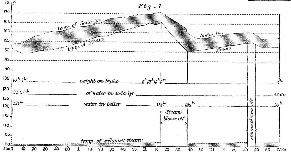
FIG. 1.
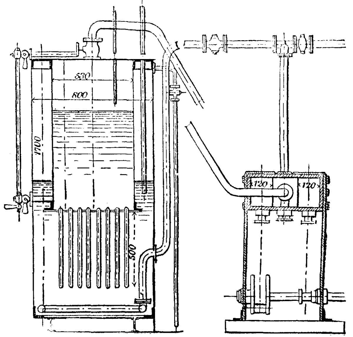
FIG. 2.
The constant rise of both temperatures during the first two hours, which is an undesirable feature of this experiment, was caused by the quantity of soda lye being too great in proportion to that of water, and other experiments have shown that it is also caused by an increased resistance of the engine, and consequent greater consumption of steam. In the latter part of the experiment, where the engine worked with expansion, the rise of the temperature was much less, and by its judicious application, together with a proper proportion between the quantities of the two liquids in the engines, which are now in practical use, the rising of the temperatures has been avoided. The smaller the difference is between the temperatures of the soda lye and the water the more favorable is the economical working of the process. It can be attained by an increase of the heating surface as well as by a sparing consumption of steam, together with an ample quantity of soda lye, especially if the steam is made dry by superheating. In the diagrams Figs. 3 and 4, taken from a passenger engine which does regular service on the railway between Wurselen and Stolberg, the difference of the two temperatures is generally less than. 10 deg. Cent. These diagrams contain the temperatures during the four journeys a b c d, which are performed with only one quantity of soda lye during about twelve hours, and show the effects of the changing resistances of the engine and of the duration of the process upon the steam pressure, which, considering the condition of the gradients, are generally not greater than in an ordinary locomotive engine. It can especially be seen from these diagrams that an increase of the resistance is immediately and automatically followed by an increased production of steam. This is an important advantage of the soda engine over the coal-burning engine, in consequence of which less skill is required for the regular production of steam power. The tramway engines of more recent construction according to Honigmann's system—Figs. 5 and 6—are worked with a closed soda vessel in which a pressure of 1/2 to 1½ atmospheres is gradually developed during the process. While the counter pressure thus produced offers only a slight disadvantage, being at an average only 1/2 atmosphere, the absorbing power of the soda lye is materially increased, as shown by the following table, and it is, therefore, possible to work with higher pressures than with an open soda vessel. Besides this great advantage, it is also of importance that the pressure in the steam boiler can be kept at a more uniform height.
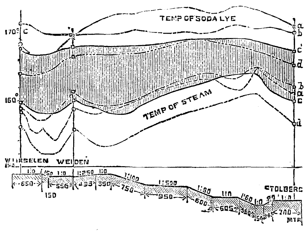
FIG. 3.
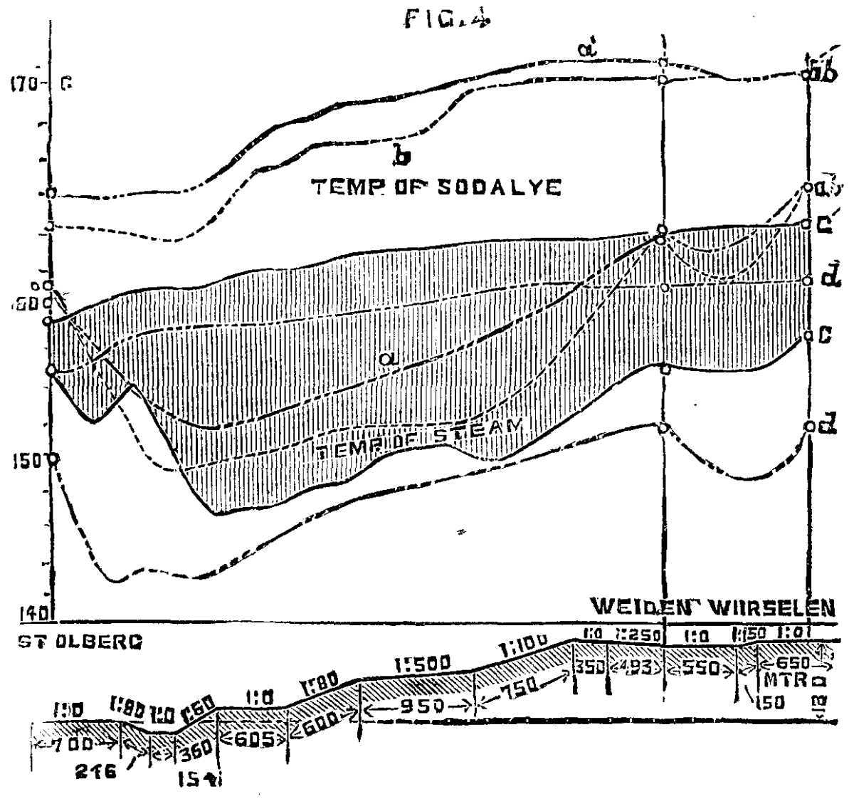
FIG. 4.
TABLE.—100 kilogs. Soda Lye containing 20 parts Water with a corresponding boiling point of 220 deg. Cent. absorb Steam as follows:
+----------------------------------+--------------+---------------+
|Final pressure in condenser.      |              |               |
+----------------------------------+Pressure in   |Corresponding  |
|  0    | ½ atm. | 1 atm. | 1½ atm.|steam boiler. | temperature.  |
+----------------------------------+--------------+---------------+
|80 kil.|125 kil.|200 kil.|350 kil.|  2 atm.      | 136.0 deg. C. |
|65  "  | 88  "  |130  "  |190  "  |  3  "        | 143.0   "     |
|51  "  | 70  "  | 98  "  |125  "  |  4  "        | 153.3   "     |
|41  "  | 58  "  | 80  "  |100  "  |  5  "        | 160.0   "     |
|34  "  | 48  "  | 66  "  | 80  "  |  6  "        | 166.5   "     |
|27  "  | 40  "  | 55  "  | 70  "  |  7  "        | 172.1   "     |
|22½ "  | 33  "  | 47  "  | 60  "  |  8  "        | 177.4   "     |
|19  "  | 28  "  | 41  "  | 52  "  |  9  "        | 182.0   "     |
|16  "  | 24  "  | 35  "  | 46  "  | 10  "        | 186.0   "     |
|12  "  | 18  "  | 28  "  | 35  "  | 12  "        | 193.7   "     |
| 9  "  | 14  "  | 22  "  | 33  "  | 15  "        | 200.0   "     |
| 2  "  |  8  "  | 12  "  | 21  "  | 20  "        | 215.0   "     |
+-------+--------+--------+--------+--------------+---------------+
Not the least important part of the process with regard to its economy is the boiling down of the soda lye in order to bring it back to the degree of concentration which is required at the beginning of the process. This is done in fixed boilers at a station from which the engines start on their daily service, and to which they return for the purpose of being refilled with concentrated soda lye. It is clear that a closed soda vessel has produced as much steam when the process is over as it has absorbed, and the quantity of coal required for the evaporation of water in concentrating the soda lye can therefore be directly compared with that required in an ordinary engine for the production of an equal quantity of steam. The boiling down of the soda lye requires, according to its degree of concentration, more coal than the evaporation of water does under equal circumstances, and disregarding certain advantages which the new engine offers in the economy of the use of steam, a greater consumption of coal must be expected. But even at the small installation for the Aix la Chapelle-Burtscheid tramway with only two boilers of four square meters heating surface each, made of cast iron 20 mm. thick, 1 kilog. of coal converts 6 kilogs. of water contained in the soda lye into steam, while in an ordinary locomotive engine of most modern construction the effect produced is not greater than 1 in 10. There can be no doubt that better results could be obtained if the installation were larger, the construction of the boilers more scientific, and their material copper instead of cast iron; but even without such improvements the cost of boiling down the soda lye might be greatly lessened by the use of cheaper fuel than that which is used in locomotive engines, and by the saving in stokers' wages, since stokers would not be required to accompany the engines.
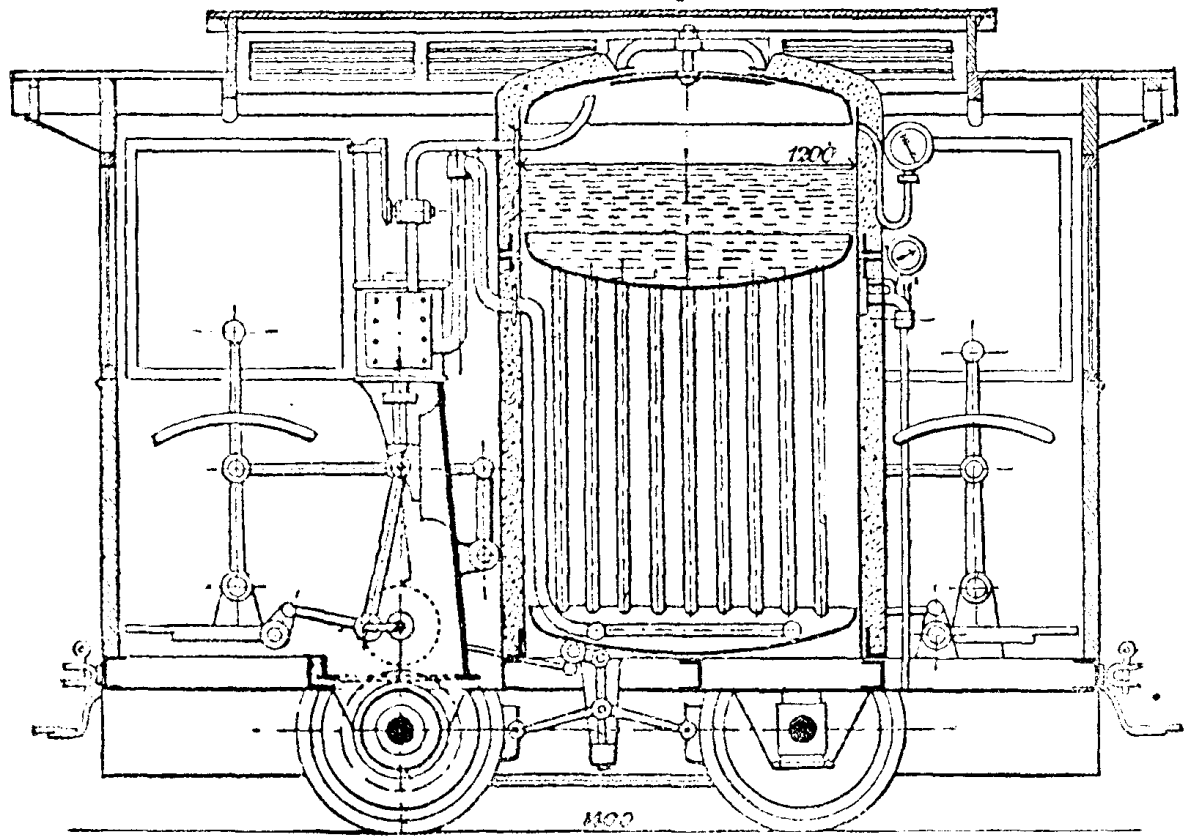
FIG. 5
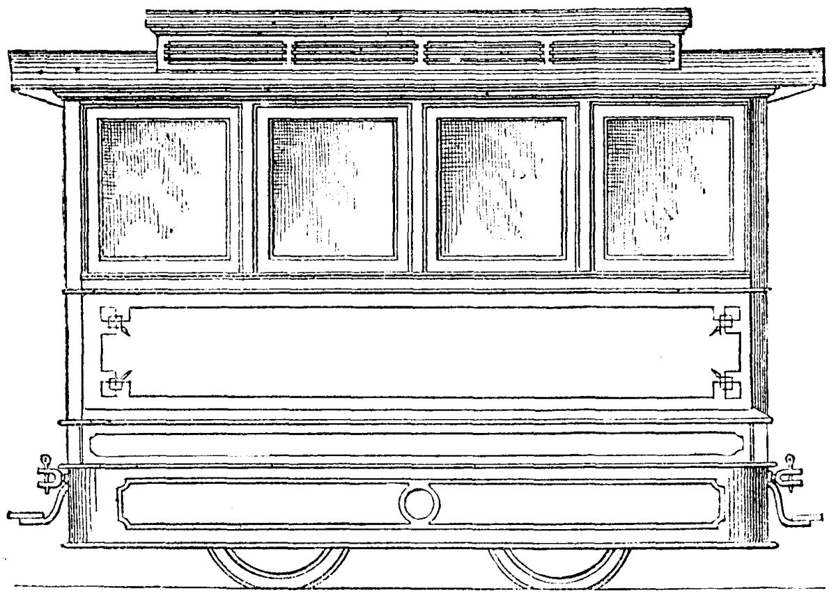
FIG. 6
Apart from these considerations, the Honigmann engines have the great advantage that neither smoke nor steam is ejected from them, and that they work noiselessly. The cost of the caustic soda does not form an important item in the economy of the process, as no decrease of the original quantities had been ascertained after a service of four months duration. Besides the passenger engine already referred to, which was tested by Herr Heusinger von Waldegg4 in March, 1884, and which since then does regular service on the Stolberg-Wurselen Railway, there are on the Aix la Chapelle-Julich railway two engines of 45,000 kilogs. weight in regular use, which are intended for the service on the St. Gothard Railway. Their construction is illustrated in Figs. 7 and 9, and other data are given in a report by the chief engineer of the Aix la Chapelle-Julich Railway, Herr Pulzner, which runs as follows:
Wurselen, Dec. 23, 1884.
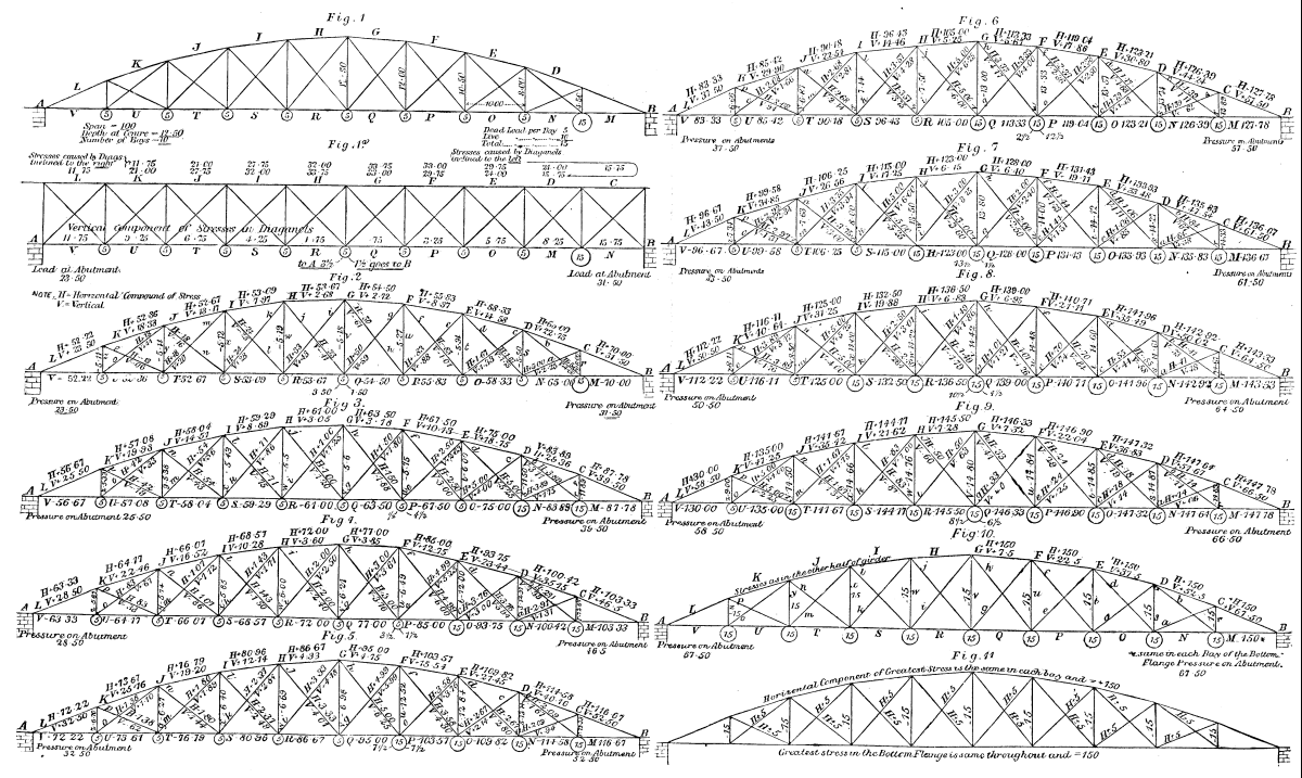
DIAGRAMS FOR THE CALCULATION OF STRESSES IN BOWSTRING GIRDERS.
A trial trip was arranged on the line Haaren-Wurselen, the hardest section of the Aix la Chapelle-Julich Railway. This section has a gradient of 1 in 65 on a length of 4 kilos; and two curves of 250 and 300 meters radius and 667 meters length. The goods train consisted of twenty-two goods wagons, sixteen of which were empty and six loaded. The total weight of the wagons was 191,720 kilogs., and this train was drawn by the soda engine with ease and within the regulation time, while the steam pressure was almost constant, viz., five atmospheres. The greatest load admissible for the coal burning engines of 45,000 kilogs. weight on the same section is 180,000 kilogs.
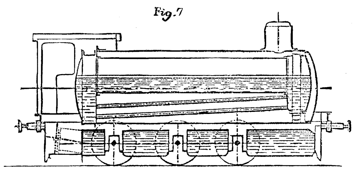
FIG. 7.
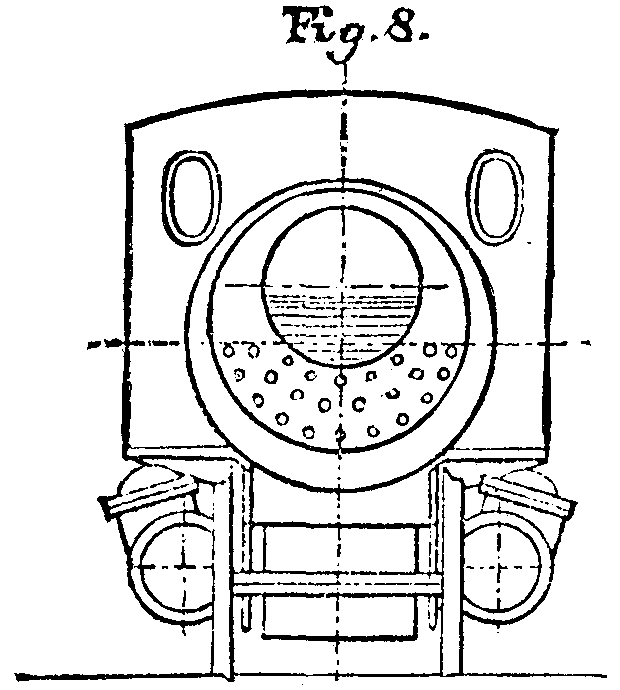
FIG. 8.
Proof is therefore given that the soda engine has a working capacity which is at least equal to that of the coal burning engine. The heating surface of the soda engine, moreover, is 85 square meters, while that of the corresponding new Henschel engine is 92 square meters. On a former occasion I have already stated that the soda engine is capable not only of performing powerful work and of producing a large quantity of steam during a short time, but also of travelling long distances with the same quantity of soda. Thus, for example, a regular passenger train, with military transport of ten carriages, was conveyed on Nov. 6, 1884, from Aix la Chapelle to Julich and back, i.e., a distance of 45 kilos, by means of the fireless engine. The gradients on this line are 1 in 100, 1 in 80, and 1 in 65, being a total elevation of about 200 meters. For a performance like this a powerful engine is required, and a proof of it can be recognized in the consumption of steam during the journey, for the quantity of water evaporated and absorbed by 4½ to 5 cubic meters soda lye was 6,500 liters.
Another certificate concerning the tramway engine illustrated in Figs. 5 and 6 is of equal interest, and runs as follows:
Aix la Chapelle, Jan. 5, 1885.
A fireless soda engine, together with evaporating apparatus, has been at work on the Aix la Chapelle-Burtscheid tramway for the last half year. In order to test the working capacity of this locomotive engine, and the consumption of fuel on a certain day, the Honigmann locomotive engine was put to work this day from 8:45 o'clock a.m. till 8 o'clock p.m., with a pause of three-quarters of an hour for the second quantity of soda lye. The engine was, therefore, at work for fully 10½ hours, viz., 5½ hours, with the first quantity, and five with the second. The distance between Heinrichsalle and Wilhelmstrasse, where the engine performed the regular service, is 1 kilo, and there are gradients
Of about 1 in 30 in 400 meter length.
   "     1  " 45  " 250    "
   "     1  " 72  " 350    "
This distance was traversed sixty-four times, the total distance, including the journeys to the station, being 66 kilos. The engine gives off fully 15-horse power on the steepest gradient, the total traction weight being 8½ to 9 tons; it is worked with an average steam pressure of 5 atmospheres, and has cylinders of 180 mm. diameter and 220 mm. stroke, cog wheel-gear of 2 to 3, and driving wheels of 700 mm. diameter. The quantity of water evaporated during the service time of 10½ hours was found to be about 1,600 kilogs., consequently about 800 kilogs. steam was absorbed by one quantity of soda, the weight of which was ascertained at about 1,100 kilogs. The averaging heating surface is 9.8 square meters; the difference of temperature between soda lye and water was toward the end only 3 deg. Cent.; 234 kilogs. pitcoal were used for boiling down the lye for the 10½ hours' service, which corresponds to a 6.6 fold evaporation.
(Signed) M.F. GUTERMUTH,
Assistant for Engineering at the Technical High School.
HASELMANN,
Manager of the Aix la Chapelle-Burtscheid Tramway.
Here are some unquestionable results. For nearly a year the first railway engine, and for six months the first tramway engine of this new construction, have been introduced into regular public service, and been open to public inspection as well as to the criticism of the scientific world. They are worked with greater ease and simplicity than ordinary locomotive engines; the economy of their working appears, allowing for shortcomings unavoidably attached to small establishments, to be at least equally great: they do not emit either steam or smoke, and their action is as noiseless as that of stationary engines.
In view of these facts it might be expected that railway managers, who are continually told that the smoke of their engines is a serious annoyance to the public, would be eager to make themselves acquainted with them; it might, in particular, be expected that the managers of the underground and suburban railways of this metropolis would lose no time in making experiments on their own lines—if only by converting some of their old engines into those of the fireless system—and assist a little in the development of an invention, in the success of which they have a tangible interest which is much greater than that of any railway on the Continent, but there is no sign yet of their having done anything.—E., in The Engineer.
[3]Bowstring Girders.—Having had occasion to get out the stresses in girders of the bowstring form, the author was not satisfied with the common formulæ for the diagonal braces, which, owing to the difficulty of apportioning the stresses amongst five members meeting in one point, were to a large extent based on an assumption as to the course taken by the stresses. As far as he could ascertain it, the ordinary method was to assume that one set of diagonals, or those inclined, say, to the right-hand, acted at one time, and those inclined in the opposite direction at another time, and, in making the calculations, the apportionment of the stresses was effected by omitting one set. Calculations made in this way give results which would justify the common method adopted in the construction of bowstring girders, viz., of bracing the verticals and leaving the diagonal unbraced; but an inspection of many existing examples of these bridges during the passing of the live load showed that there was something defective in them. The long unbraced ties vibrated considerably, and evidently got slack during a part of the time that the live load was passing over the bridge. In order to get some definite formulæ for these girders free from any assumed conditions as to the course taken by the stresses, or their apportionment amongst the several members meeting at each joint, the author adopted the following method, which, he believes, has not hitherto been used by engineers:
Let Fig. 1 represent a bowstring girder, the stresses in which it is desired to ascertain under the loads shown on it by the circles, the figures in the small circles representing the dead load per bay, and that in the large circle the total of live and dead load per bay of the main girders. A girder, Fig. 1A, with parallel flanges, verticals, and diagonals, and depth equal to the length of one bay, was drawn with the same loading as the bowstring. The stresses in the flanges were taken out, as shown in the figure, keeping separate those caused by diagonals inclined to the left from those caused by diagonals inclined to the right. The vertical component of the stress in the end bay of the top flange of the bowstring girder, Fig. 1, was, of course, equal to the pressure on the abutment, and the stress in the first bay of the bottom flange and the horizontal component of the stress in the first bay of the top flange was obtained by multiplying this pressure by the length of the bay and dividing by the length of the first vertical. The horizontal component of the stress in any other bay of the top or bottom flange of the bowstring girder—Fig. 1—was found by adding together the product of the stress in the parallel flanged girder, caused by diagonals inclining to the right, divided by the depth of the bowstring girder at the left of the bay, and multiplied by the depth of the parallel flanged girder; and the product of the stress caused by diagonals inclining to the left divided by the depth of the bowstring girder at the right of the bay, multiplied by the depth of the parallel flanged girder. Thus the horizontal component of the stress in D=
 _                                                                _
| Stress caused by diagonals   Length of right   Depth of parallel |
|      leaning to left.           vertical.       flanged girder.  |
|                                                                  | +
|_           15.75            ×       1/4.5     ×        10       _|
 _                                                                _
| Stress caused by diagonals   Length of ver-    Depth of parallel |
|     leaning to right.        tical to left.     flanged girder.  |
|                                                                  |
|_           24               ×       1/8       ×        10       _|

= 65; and the vertical component =

   Horizontal component.            Length of bay.

          65               ×       1/10   × (8.0 - 4.5) = 22.75.
In the same way the horizontal and vertical components of the stresses in each of the other bays of the flanges of the bowstring were found; and the stresses in the verticals and diagonals were found by addition, subtraction, and reduction. These calculations are shown on the table, Fig 1B. The result of this is a complete set of stresses in all the members of the bowstring girder—see Fig. 2—which produce a state of equilibrium at each point. The fact that this state of equilibrium is produced proves conclusively that the rule above described and thus applied, although possibly it may be considered empirical, results in the correct solution of the question, and that the stresses shown are actually those which the girder would have to sustain under the given position of the live load. Figs. 2 to 10 inclusive show stresses arrived at in this manner for every position of the live load. An inspection of these diagrams shows: a. That there is no single instance of compression in a vertical member of the bowstring girder, b. That every one of the diagonals is subjected to compression at some point or other in the passage of the live load over the bridge, c. That the maximum horizontal component of the stresses in each of the diagonals is a constant quantity, not only for tension and compression, but for all the diagonals. The diagrams also show the following facts, which are, however, recognized in the common formulæ: d. The maximum stress in any vertical is equal to the sum of the amounts of the live and dead loads per bay of the girder. e. The maximum horizontal component of the stresses in any bay of the top flange is the same for each bay, and is equal to the maximum stress in the bottom flange. Having taken out the stresses in several forms of bowstring girders, differing from each other in the proportion of depth to span, the number of bays in the girder, and the amounts and ratios of the live and dead loads, similar results were invariably found, and a consideration of the various sets of calculations resulted in the following empirical rule for the stresses in the diagonals: "The horizontal component of the greatest stress in any diagonal, which will be both compressive and tensile, and is the same for every diagonal brace in the girder, is equal to the amount of the live load per bay multiplied by the span of the girder, and divided by sixteen times the depth of girder at center." The following formulæ will give all the stresses in the bowstring girder, without the necessity of any diagrams, or basing any calculations on the assumed action of any of the members of the girders:
Let S = span of girder.
    D = depth at center.
    B = length of one bay.
    N = number of bays.
    L = length of any bay of top flange.
    l = length of any diagonal.
    w = dead load per bay of girder.
    w¹= live load per bay of girder.
    W = total load per bay of girder = w + w¹.

Then: S/B = N.

Bottom Flange. WNS/8D = maximum stress throughout.          (1)

Top Flange.--In any bay the maximum stress =

+ WNS/8D × L/B = + WLN²/8D                                  (2)

Verticals.--The maximum stress = -W.                        (3)

Diagonals.--The maximum stress is

± w¹lS/16DB = ± w¹lN/16D                                    (4)
These results show that the method generally adopted in the construction of bowstring girders is erroneous; and one consequence of the method is the observed looseness and rattling of the long embraced ties referred to at the commencement of the article during the passage of the live load; the fact being that they have at such times to sustain a compressive stress, which slightly buckles them, and sets them vibrating when they recover their original position.
Another necessity of the common method of construction is the use of an unnecessary quantity of metal in the diagonals; for, by leaving them unbraced, the set of diagonals which does act is subjected to exactly twice the stress which would be caused in it if the bridge was properly constructed. A comparison of the results of a set of calculations on the common plan with those given in this paper, shows at once that this is the case; for the ordinary system of calculation the stresses, in addition to showing compression in the verticals, gives exactly twice the amount of tension in the diagonals which they should have.
FIG. 1B.
_______________________________________________________________________________
                                            |
          Top Flange Stresses.              |      Stresses in Diagonals.
                               Hor.    Ver. |
                                            |
C= 31.5  × 10/4.5  =         +70.00 = 31.50 |a = 70   -65         =+5.00 = 2.25
                                            |
   15.75 × 10/4.5  = 35                     |b =  "     "         =-5.00 = 4.00
                          \                 |
D                          > +65.00 = 22.75 |c = 65   -58.33-5    =+1.67 = 1.33
                          /                 |
   24    × 10/8    = 30                     |d =  "      "   "    =-1.67 = 1.75
                          \                 |
E                          > +58.33 = 14.58 |e = 58.33-55.83-1.67 =+ .83 =  .88
                          /                 |
   29.75 × 10/10.5 = 28.33                  |f =   "     "     "  =- .83 = 1.01
                          \                 |
F                          > +55.83 =  8.37 |g = 55.83-54.50- .83 =+ .50 =  .59
                          /                 |
   33    × 10/12   = 27.5                   |h =   "     "     "  =- .50 =  .61
                          \                 |
G                          > +54.50 =  2.72 |i = 54.50-53.67- .50 =+ .33 =  .43
                          /                 |
   33.75 × 10/12.5 = 27                     |j =   "     "     "  =- .33 =  .41
                          \                 |
H                          > +53.67 =  2.68 |k = 53.67-53.09- .33 =+ .24 =  .28
                          /                 |
   32    × 10/12   = 26.67                  |l =   "     "     "  =- .24 =  .24
                          \                 |
I                          > +53.09 =  7.97 |m = 53.09-52.67- .24 =+ .18 =  .20
                          /                 |
   27.75 × 10/10.5 = 26.42                  |n =   "     "     "  =+ .18 =  .16
                          \                 |
J                          > +52.67 = 13.17 |o = 52.67-52.36- .18 =+ .13 =  .11
                          /                 |
   21    × 10/8    = 26.25                  |p =   "     "     "  =- .13 =  .06
                          \                 |
K                          > +52.36 = 18.33 |
                          /                 |
   11.75 × 10/4.5  = 26.11                  |
                                            |
L= 23.5  × 10/4.5  =         +52.22 = 23.50 |
____________________________________________|___________________________________
                                            |
      Bottom Flange Stresses.        |    Stresses in Verticals.
                                            |
                          Hor.              |                              Ver.
           M same as C = 70.00              |    r = 15 - 4           = - 11.00
           N    "    D = 65.00              |    s =  5 + 2.25 - 1.75 = -  5.50
           O    "    E = 58.33              |    t =  5 + 1.33 - 1.01 = -  5.32
           P    "    F = 55.83              |    u =  5 +  .88 -  .61 = -  5.27
           Q    "    G = 54.50              |    v =  5 +  .59 -  .41 = -  5.18
           R    "    H = 53.67              |    w =  5 +  .43 -  .24 = -  5.19
           S    "    I = 53.09              |    x =  5 +  .28 -  .16 = -  5.12
           T    "    J = 52.67              |    y =  5 +  .20 -  .06 = -  5.14
           U    "    K = 52.36              |    z =  5 +  .11        = -  5.11
           V    "    L = 52.22              |
____________________________________________|____________________________________
—The Engineer.
An exhibition of a spring car motor was given at a recent date at the works of the United States Spring Motor Construction Company, Twelfth Street and Montgomery Avenue. As a practical illustration of the operation of the motor a large platform car, containing a number of invited guests and representatives of the press, was propelled on a track the length of the shop. (This was in 1883.) The engine, if such it may be called, was of the size which is intended to be used on elevated railways. As constructed, the motor combines with a stationary shaft a series of drums, carrying springs, and arranged so that they can be brought into use singly or in pairs. Each spring or section has sufficient capacity to run the car, and thus as one spring is used another is applied. There is a series of clutches by which the drums to which the springs are attached are connected, with a master wheel, which transmits through a train of wheels the power of the springs to the axles, of the truck wheels. The motor will be so constructed that it may be placed on a truck of the width of the cars at present in use, and will be nine feet long, with four traction wheels. It is proposed do away with the two front wheels and platform, so that the front of the car may rest on a spring to the truck. There will be an engine at each end of the road, which, it is calculated, will wind up the springs in at least two minutes' time.
While the mere construction of such a working motor involved nothing new, the real problem involved consisted of the rolling of a piece of steel 300 feet long, 6 inches wide, and a quarter of an inch thick. Another element was the coiling of this strip of steel preliminary to tempering. To temper it straight was to expose the grain to unnecessary strain when wound in a close coil. To overcome this was the most difficult part of the work. At the exhibition the inventor gave an illustration of the method which has been employed by the company. The strip of steel is slowly passed through a retort heated by the admixture of gas and air at the point of ignition in proportions to produce intense heat. When the strip has been brought to almost a white heat, it is passed between two rollers of the coiling machine. It is then subjected to a powerful blast of compressed air and sprays of water, so that six inches from the machine the steel is cold enough for the hand to be placed on it. After this operation the spring is complete and ready to be placed on the shaft. The use of the springs is said to be beyond estimate. They may be employed to operate passenger elevators, the springs being wound by a hand crank. It is understood that the French Government has applied for them for running small yachts for harbor service. Among the advantages claimed for this motor are its cheapness in first cost and in operating expenses. It is estimated that an engine of twenty-five horse power will be required at the station to wind the springs. If there be one at each end of the line, the cost for fuel, engineer, and interest will not exceed $100 per week. This will answer for fifty or any additional number of cars. The company claims that by using twelve springs, each 150 feet in length, an ordinary street car can be driven about twenty miles.—Phil. Inquirer.
We show herewith the method employed by the Baltimore Car Wheel Company in casting chilled wheels to prevent tread defects. The ordinary mode of pouring from the ladle into the hub part of the mould, and then letting the metal overpour down the brackets to the chill, produces cold shot, seams, etc. In the arrangement here shown the hub core, A, has a concave top, B, and the core seat, C, is convex, its center part being lower than the perimeter of the top of the core. Figs. 3, 4, show the core, A, in the side elevation and in plain. Fig. 2 is a core point forming a space to connect the receiving chamber, E, above, with the mould by passageways, D D, formed in the side of the top of the core. The combined area of these passageways being less than that of the conduit, F, from the receiving chamber, the metal is skimmed of impurities, and the latter are retained in the receiving chamber, E. The entering metal flows first to the lower hub part at H H, thence by the sprue-ways, G G, to the lower rim part at J J, being again skimmed at the mouth of the sprue-ways. Thus the rim fills as rapidly as the hub, and the metal is of a uniform and high temperature when it reaches the chill.
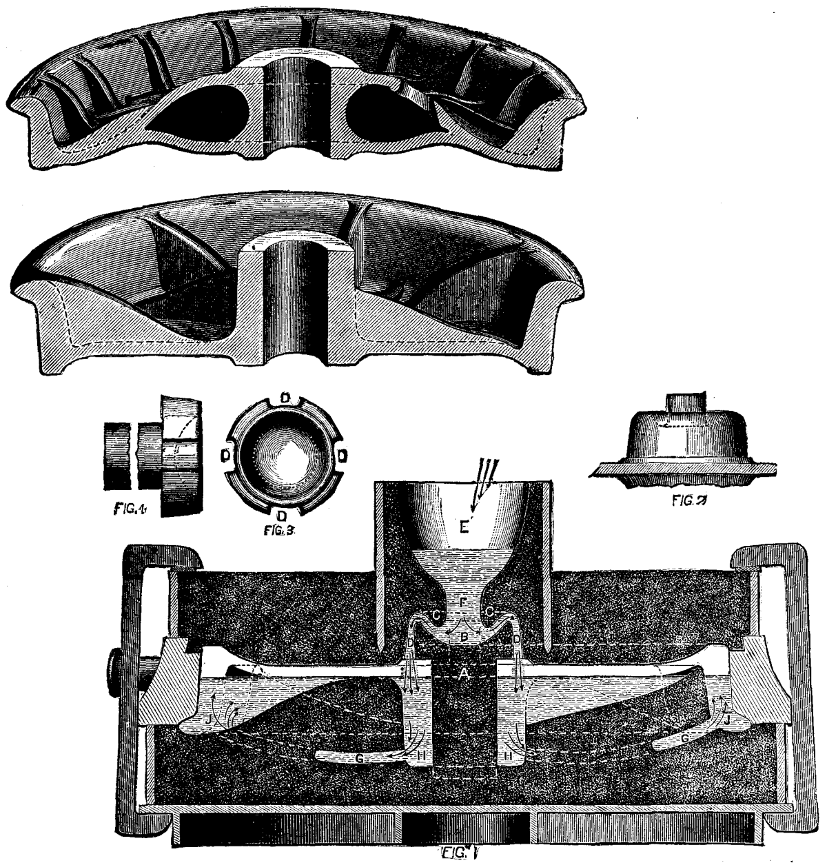
CASTING OF CAR WHEELS.
In the wheels made by this firm, every alternate rib is connected with the rim, and runs off to nothing near the hub; the intermediate ribs are attached to the hub, and diminish in width toward the rim.—Jour. Railway App.
The wonderful ease with which electricity adapts itself to the production of mechanical, calorific, and luminious effects at a distance, long ago gave rise to the idea of applying it to certain curious and amusing effects that simple minds willingly style supernatural, because of their powerlessness to find a satisfactory explanation of them.
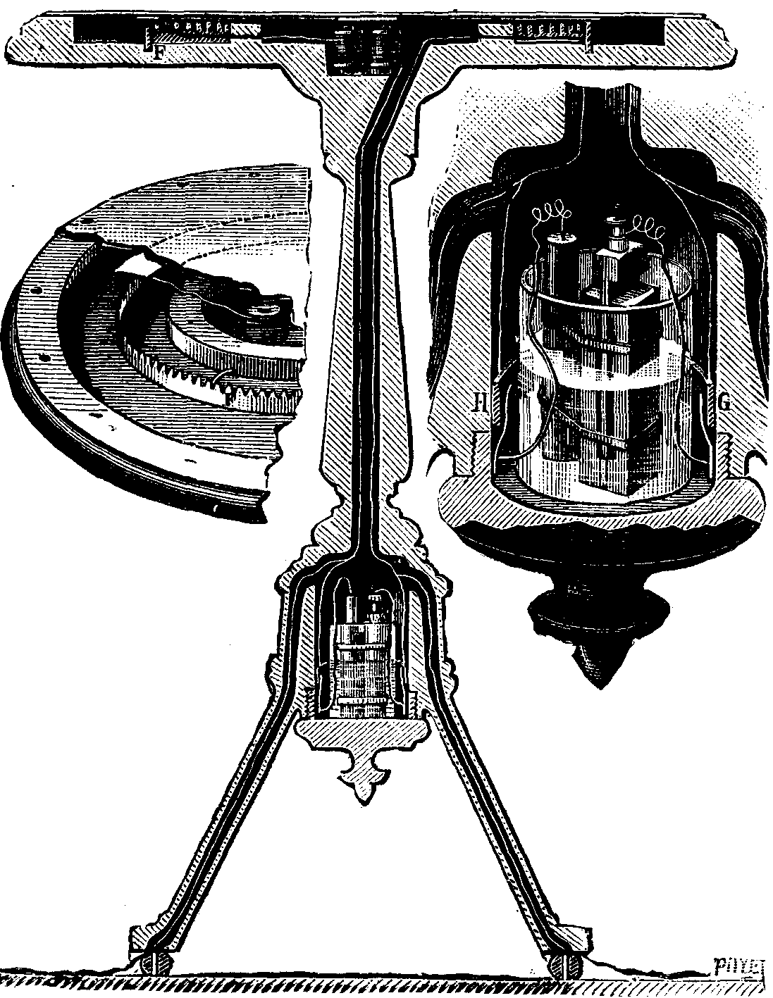
FIG. 1.—RAPPING AND TALKING TABLE.
Who has not seen, of old, Robert Houdin's heavy chest and Robert Houdin's magic drum? These two curious experiments are, as well known, founded upon the properties of electro-magnets.
At present we shall make known two other arrangements, which are based upon the same action, and which, presenting old experiments under a new form, rejuvenate them by giving them another interest.
The first apparatus (Fig. 1), which presents the appearance of an ordinary round center table, permits of reproducing at will the "spirit rappings" and sepulchral voice experiments. The table support contains a Leclanche pile, of compact form, carefully hidden in the part that connects the three legs. The top of the table is in two parts, the lower of which is hollow, and the upper forms a cover three or four millimeters in thickness. In the center of the hollow part is placed a vertical electro-magnet, one of the wires of which communicates with one of the poles of the pile, and the other with a flat metallic circle glued to the cover of the table. Beneath this circle, and at a slight distance from it, there is a toothed circle, F, connected with the other pole of the pile. When the table is pressed lightly upon, the cover bends and the flat circle touches the toothed one, closes the circuit of the pile upon the electro-magnet, which latter attracts its armature and produces a sharp blow. On raising the hand, the cover takes its initial position, breaks the circuit anew, and produces another sharp blow. Upon running the hand lightly over the table, the cover is caused to bend successively over a certain portion of its circumference, contacts and breakages of the circuit are produced upon a certain number of the teeth, and the sharp blow is replaced by a quick succession of sounds, or a tremulous one, according to the skill of the medium whose business it is to interrogate the spirits. As the table contains within it all the mechanism that actuates it, it may be moved about without allowing the artifice to be suspected.
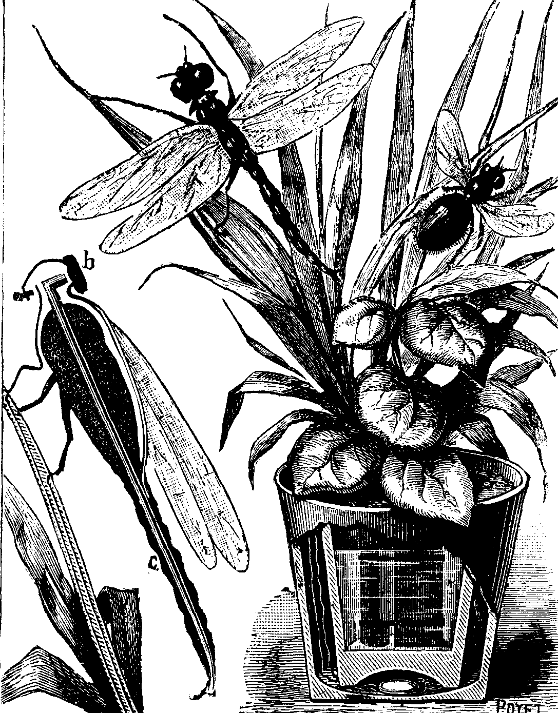
FIG. 2.—ELECTRIC INSECTS.
The table may also be operated at a distance by employing conductors passing through the legs and under the carpet and communicating with a pile whose circuit is closed at an opportune moment by a confederate located in a neighboring apartment.
Finally, on substituting a small telephone receiver for the electro-magnet, and a microtelephone system for the ordinary pile, we shall convert the rapping spirits into talking ones. With a little exercise it will be easy for the confederate to transmit the conversation of the "spirits" in employing sepulchral tones to complete the illusion.
Fig. 2 represents a device especially designed as a parlor ornament. When the plant is touched, the insects resting upon it immediately begin to flap their wings as if they desired to fly away. These insects are actuated by a Leclanche pile hidden in the pot that contains the plant. The insect itself is nothing else than a mechanism analogous to that of an ordinary vibrating bell. The body forms the core of a straight electro-magnet, c, which is bent at right angles at its upper part, and in front of which is placed a small iron disk, b, forming the animal's head. This head is fixed upon a spring, like the armature of ordinary bells, and causes the wings to move to and fro when it is successively attracted and freed by the electro-magnet. The current is interrupted by means of a small vibrating device whose mode of operation may be easily understood by glancing at the section in Fig. 2. The current enters the electro-magnet through a fine copper wire hidden in the leaves and connected with the positive pole of the pile. The negative pole is connected with the bottom of the pot. The wire from the vibrator of each insect reaches the bottom of the flower-pot, but does not touch it. A drop of mercury occupies the bottom of the pot, where it is free to move about. It results that if the pot be taken into the hand, the exceedingly mobile mercury will roll over the bottom and close the circuit successively on the different insects, and keep them in motion until the pot has been put down and the drop of mercury has become immovable.
One of the most difficult problems that daily presents itself in large cities is how to proceed without danger in the search for leakages in gas mains, or in attempts to save life in houses accidentally filled with explosive gases. The introduction of a flame into such places leads in the majority of cases to accidents whose consequences cannot be estimated. The reader will remember especially the explosion which occurred some time ago in St. Denis Street, Paris, and which killed a considerable number of persons. It has, therefore, been but natural to think of the use of electricity, which gives a bright line without a flame, in order to allow life-saving corps and firemen to enter buildings filled with an explosive mixture, without any risk whatever.
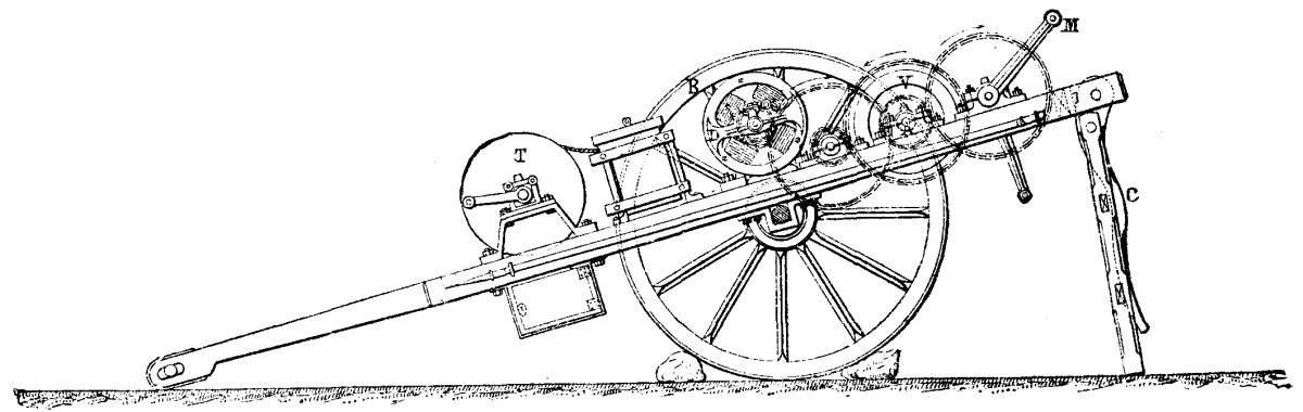
FIG. 1.—ELEVATION (Scale 1/25).
Several electricians have proposed ingenious portable apparatus for this purpose, and, among these, Mr. A. Gerard, whose device we illustrate herewith. In this system the electric generator is stationary, and remains outside the building. This, along with all the rest of the apparatus, is mounted upon a carriage. The operator, instead of carrying a pile to feed the lamp, drags after him a very elastic cable containing the two conductors. This "Ariadne's thread" easily follows all sinuosities, and adapts itself to all circumvolutions. The entire apparatus, being mounted upon a carriage, can be easily drawn to the place of accident like a fire engine.
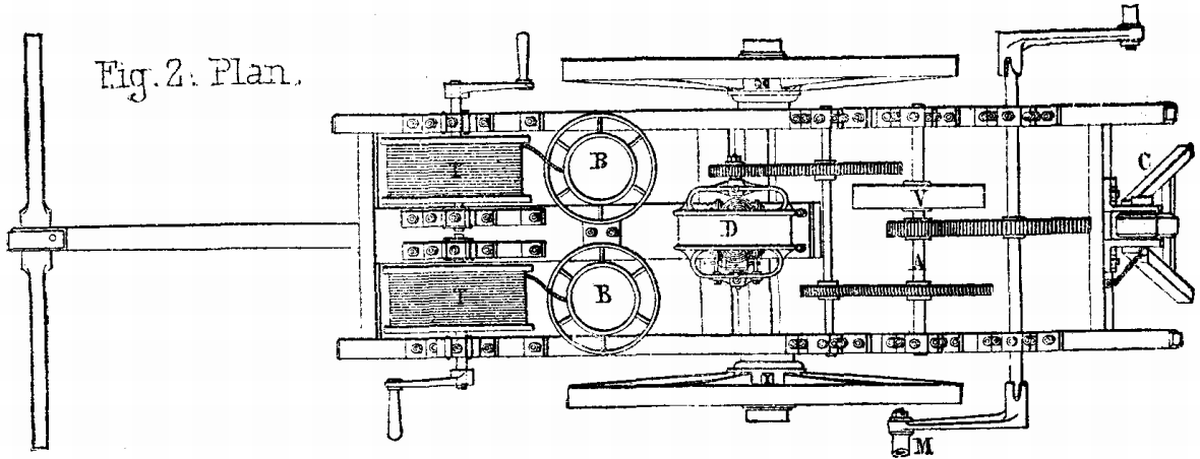
FIG. 2.—PLAN (Scale 1/25).
General Description.—Fig. 1 shows the carriage. In the center, over the axle, is mounted a dynamo-electric, machine, D, driven by a series of gear wheels that are revolved by winches, MM. Upon the shaft, A, is fixed a hand wheel, V, designed to regulate the motion. In the forepart of the carriage are placed two windlasses, TT, permanently connected with the terminals of the dynamo. Upon each of these is wound a cable formed of two conductors, insulated with caoutchouc and confined in the same sheath. Each windlass is provided with five hundred feet of this cable, the extremity of which is attached to two lanterns each containing an incandescent lamp. These lanterns, are inclosed in boxes, BB, with double sides, and cross braced with springs so as to diminish shocks. Under the windlass there is a case which is divided into two compartments, one of which contains tools and fittings, and the other, six carefully packed incandescent lamps, to be used in case of accident to the lanterns. At the rear end of the carriage there is a hinged bar, C, designed to support it at this point and give it greater stability during the maneuvers. The stability is further increased by chocking the wheels.
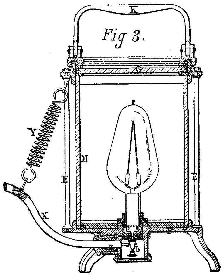
FIG. 3.—HAND LANTERN (Scale 1/4).
Maneuver of the Apparatus.—The carriage, having reached the place of accident, is put in place, its rear end is supported by the bar, C, the wheels are chocked, and the winches are placed upon the dynamo gearing. Two strong men selected for the purpose now seize the winches and begin to revolve them, and the lamps immediately light while in their boxes. Another man, having opened the latter, takes out one of the lanterns and enters the dangerous place, dragging after him the elastic cable that unwinds from the windlass. Two men are sufficient to turn the winches for five minutes; with a force of six men to relieve one another the apparatus may therefore be run continuously.
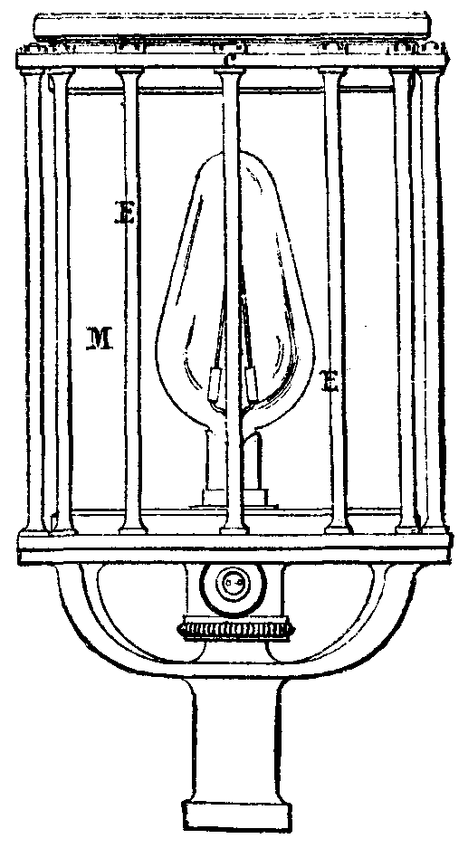
FIG. 4.—POLE LANTERN (Scale 1/4).
The dynamo, which is of strong and simple construction, is inclosed in a cast iron drum, and is consequently protected against accident. With a power of 25 kilogrammeters it furnishes a current of 40 volts and 7 amperes, which is more than sufficient to run two 50-candle incandescent lamps. The winches are removable, and are not put upon the shaft until the moment they are to be used.
The windlasses, as above stated, are permanently connected with the terminals of the dynamos. The current is led to them through their bearings and journals. Their shaft is in two pieces, insulated from one another. One extremity of the cable is attached to these two pieces, and the other to the lantern. Each windlass is provided with a small winch that allows the cable to be wound up quickly.
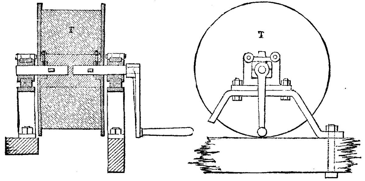
FIG. 5.—WINDLASS (Scale 1/10).
The two lanterns are different, on account of the unlike uses to which they are to be put. One of them is a hand-lamp that permits of making a quick preliminary exploration. The second is to be fixed by a socket beneath it to a pole that is placed along the shafts of the carriage. This lantern, upon being thrust into a chimney, shaft, or well, permits of a careful examination being made thereof. As the handle terminates in a point; it may be stuck into the ground, to give a light at a sufficient height to illuminate the surroundings.
The hand lantern consists of a base, P, provided with three feet. At the top there is a threaded circle to which is attached a movable handle, K, that is screwed on to a ring, C. These three pieces, which are of bronze, are connected by 12 steel braces, E, that form a protection for the glass, M. The lantern is closed above by a thick glass disk, G. The luminous rays are therefore capable of spreading in all directions. Tight joints are formed at every point by rubber or leather washers.
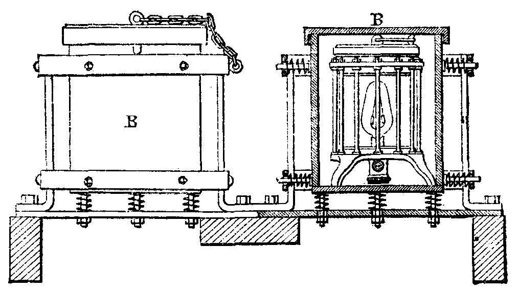
FIG. 6.—LANTERN BOX (Scale 1/10).
In the center of the lantern is placed the incandescent lamp. This is held in a socket, and is provided with two armatures to which the platinum wires are soldered. Two terminals, b, are affixed to the lamp socket. Beneath the lantern there is a cylindrical box provided with a screw cap. In one side of this box there is a tubulure that gives passage to the electric cable whose conductors are fastened to the terminals. A conical rubber sleeve, R, incloses the cable, which is pressed by the screw cap, S. A special spring, Y, attached at one end to the top of the lantern, and at the other to the cable, X, is designed to deaden the too sudden shocks that the lantern might be submitted to, and that would tend to pull out the cable.
As a result of the peculiar arrangement of this lantern, the lamp is constantly surrounded with a certain quantity of air that would certainly suffice to consume the carbons in case of a breakage of the globe without allowing any lighted particles to escape to the exterior. Besides, should the terminals become unscrewed, and should the conductors thus rendered free produce sparks, the latter would be prevented from reaching the exterior by reason of the absolute tightness of the box. In case the incandescent lamp should get broken, the only inconvenience that would attend the accident would be that the man who held the lantern would be for a moment in the dark. When he reached the carriage, it would be only necessary for him to take off the glass disk, take the broken lamp out of its socket, insert a new one, and then put the glass top on again.—Le Génie Civil.
Voltaic batteries containing solutions of ammonium chloride and zinc chloride can, according to the recent researches of M. Onimus, be converted into dry piles by mixing these solutions with plaster of Paris, and allowing the mixture to solidify. If mixtures of ferric oxide and manganese peroxide with plaster of Paris are employed, the electromotive force is slightly higher than with plaster of Paris alone; and when ferric oxide is used, the battery quickly regains its original strength on breaking the circuit. When the battery is exhausted, the solid plaster of Paris has simply to be moistened again with the solution.
The study of the form and color that electric discharges exhibit, according to the different ways in which they are produced, has already enticed a certain number of amateurs and scientists. Every one knows the remarkable researches of the lamented Th. Du Moncel on the induction spark, and during the course of which he, in 1853, discovered that phenomenon of the electric efflux which has since been the object of important researches on the part of several physicists and chemists, among whom must be cited Messrs. Thenard, Hautefeuille, and Chapuis. Twenty years ago, Mr. Bertin, who was then Professor at the Faculty of Strassburg, and who was afterward subdirector of the normal school, was directing his researches upon the electric discharges produced by high tension apparatus, plate machines, and Leyden jars. He thought, with reason, that, on account of its rapidity and complexity, a portion of the phenomenon must escape the eye of the observer, and so the idea occurred to him to photograph the discharge in order to afterward study its forms more at his leisure. We have recently had an opportunity of seeing a negative which was obtained by him at that epoch; but the photographic processes then in use probably did not allow him to obtain others that were as satisfactory, and he had given up this kind of study, when, last year, he had an opportunity of speaking of it to the well known manufacturer Mr. F. Ducretet, whom he induced to take it up and employ the new gelatino-bromide process. Unfortunately, he died before these experiments were begun, and was unable to see the realization of his project. Mr. Ducretet did not abandon the idea, but constructed the necessary apparatus, and obtained the results that we now place before our readers.
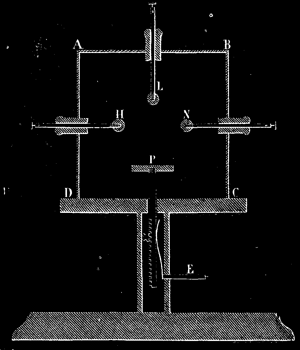
FIG 1.
His apparatus, which contains no photographic objective, consists of an oblong case, ABCD, made of red glass and resting upon an ebonite table supported by one leg (Fig. 1). In the top of the case, as well as in the two sides, AD and BC, are apertures that are closed by ebonite cylinders through which slide, with slight friction, copper rods, HLN. In the leg of the table there is a copper rack which may be maneuvered from the interior by a pinion, and which communicates electrically with a terminal, E. The upper part of this rack, which enters the glass case, is threaded, so that there may be affixed to it either a metallic or an insulating disk. The rods, HLN, are likewise threaded, so that there may be affixed to their internal extremities balls, points, combs, and disks of metal or of insulating material at will.
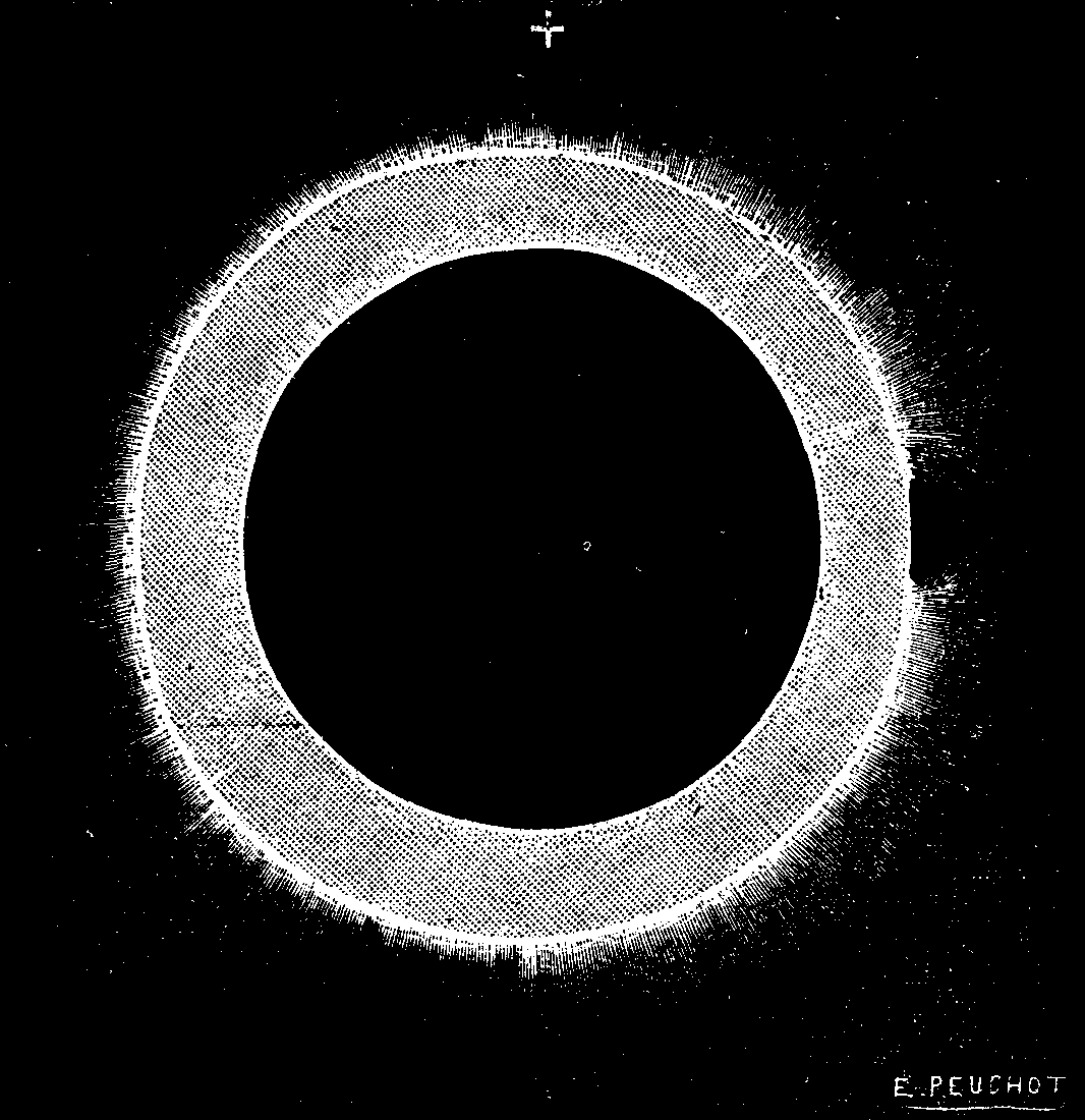
FIG 2.
In short, we have here a transparent box (impermeable to photogenic rays) into which electricity may be led by means of four conductors that are arranged two by two in a line with each other, or in perpendicular positions, and that may be made to approach or recede from one another by maneuvering them from the exterior. This very simple arrangement answers every requirement, and, upon placing a sensitized plate in the vicinity of the conductors, permits of photographing the electric discharge directly and, so to speak, before the eyes of the operator.
As a source of electricity, use is made of a bichromate of potash battery of 6 elements, capable of giving 10 volts and 15 amperes. The current from this battery is converted into a current of high tension by means of a strong induction coil capable of giving sparks more than eight inches in length. The discharge shown in Fig. 4 was obtained by means of a Holtz machine. Each experiment lasted less than a second.
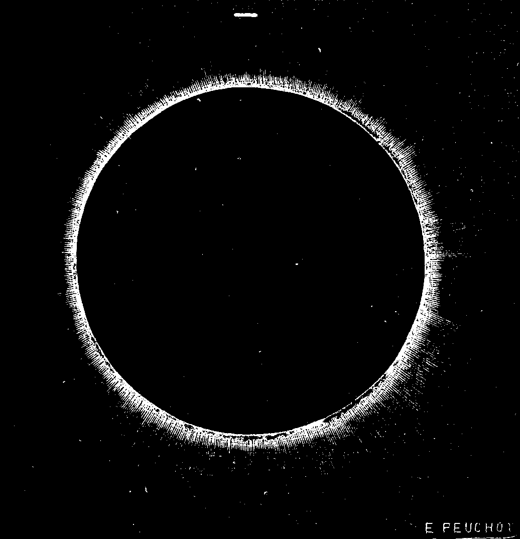
FIG. 3.
Figs. 2 and 3 represent the efflux that occurred under; the following conditions: The disk, P, was of metal, and was connected with the negative pole of the induction coil; and upon it was laid the photographic plate with the sensitized film downward, and consequently touching the disk. This is what produced the opaque circle in the center. Then the photographic plate was entirely covered with a thin ebonite plate, above which there was a second one supported by small wedges, so as to allow air to circulate between them. Finally, upon this second ebonite plate there was placed another photographic plate, with its sensitized film upward and directly in contact with an upper metallic disk, and connected with the positive pole of the coil by the conductor, L. An inspection of Figs. 2 and 3 shows that the, efflux does not possess the same form at the two poles. We remark at the positive pole a quite wide opaque circle surrounded by a sort of aureola composed of an infinite number of very delicate rays, while at the negative pole the aureola seems not to have been able to spread. We see, moreover, the same phenomenon in examining Fig. 4 (which represents the efflux obtained by means of a Holtz machine), but this time in a horizontal direction. The photographic plate was here placed upon the non-conducting disk, P. As the sensitized film was upward, it was put in contact with the balls at the extremity of the conductors, H and N.
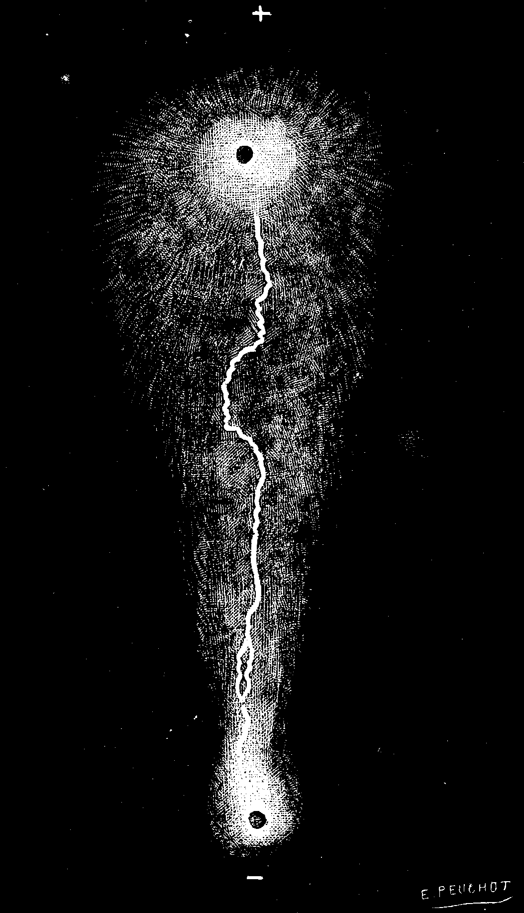
FIG. 4.
It will be seen here again that the efflux spreads out widely at the positive pole, while it is contracted at the other. The conducting balls were spaced 0.04 inch apart. A spark leaped from one to the other at the moment the current was being interrupted.
In Fig. 5 we are enabled to study with more ease a spark obtained with nearly the same arrangement. The balls, H and N, did not here rest directly upon the sensitized film, but upon two small sheets of tin cemented to the extremities of the plate at 0.06 inch apart. In addition, the source employed was not the Holtz machine, but the pile with induction coil. Two nearly parallel sparks were obtained. It will be seen that these are very complex. Each of them seems to be formed of four lines of different sizes, entangled with one another and presenting different sinuosities. Aside from this, the plate is traversed for a space of 0.04 of an inch by curved lines running from one pole to the other, and exhibiting numerous sinuosities.
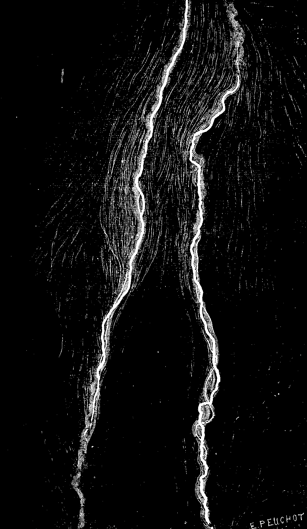
FIG. 5.
Fig. 6 represents a discharge that occurred under the following circumstances: The disk, P, being metallic and connected with one of the poles, there was placed upon it a thin ebonite plate of the same dimensions as the photographic one, and then the latter with the sensitized pellicle upward. Finally, the pellicle was put in contact with the upper conductor, L, which terminated in a ball and was connected with the other pole of the induction coil.
It will be seen that, despite the two dielectrics (ebonite and glass) interposed, and the opacity of one of them, the efflux that occurred around the disk, P, is quite sharply reproduced upon the sensitized plate by a circle like that which we observed in Figs. 2 and 3. It will be seen, besides, that an infinite number of ramifications in every direction has been produced around the ball, and we can follow the travel of the spark that leaped between the ball and disk in two directions situated in the prolongation of one another.
Under the two principal and clearly marked lines that this spark made there are seen two other, very pale and much wider ones, that present no sinuosities parallel with the first.
The results of these experiments are very curious. The position of the plates was varied in 18 different ways, as was also the form of the conductors. We have spoken of those only that appear to us to present the most interest. Unfortunately, notwithstanding the skill of the engraver, it is impossible to render with accuracy all the details that are seen upon examining the negative. The proofs that have been printed upon paper present much less sharpness than the negative, for there are certain parts of the figures on the glass that do not show in the print.
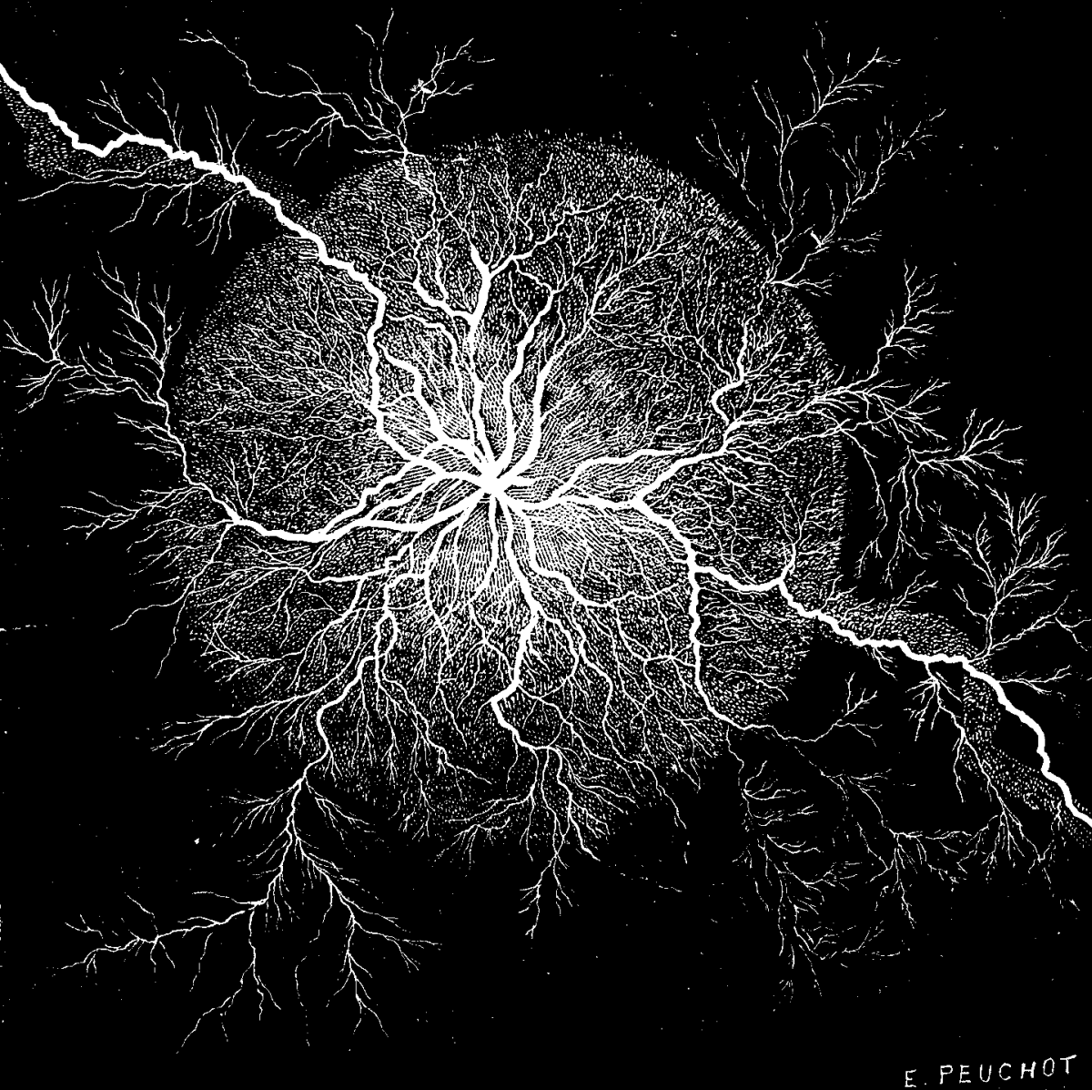
FIG. 6.
We have been content here to make known the results obtained, without drawing any conclusions from them. It is to be hoped that these experiments, which can be easily repeated by means of the apparatus described above, will be repeated and discussed by electricians, and that they will contribute toward making known to us the nature of the mysterious agent that will give its name to our era.—G. Mareschal, in La Lumiere Electrique.
Many of the readers of this journal may like to participate in the discussion of the following proposition. The statement is this:
The space through which a body, near the surface of the earth, at mean latitude, in vacuo, descends by virtue of the accelerating force of gravity in 1/1000 of an hour is precisely 2,500 geometric inches = 100 geometric cubits = the side of a square geometric acre.
[The geometric inch is taken, in accordance with the view of Sir John Herschel, at 1/1,000,000,000 of twice the polar axis of the earth, and equals 1-1/1000 English inches very nearly.]
The strict decimal relation of the proposition is shown by the following table. It has been tested by Clairaut's theorem, and by other existing expressions, and has been found to agree, far within the probable limits of errors in observation, with the most approved values of the constant. In fact, it is contained in the existing expressions; but the decimal relation does not appear unless we state the unit of linear measure as a decimal of the earth's semi-polar axis, and, at the same time, divide the circle, both for time and for general purposes, geometrically, i.e., by strict decimalization upon the hour-angle. A mathematical reason underlies the proposition.
Time in       Acquired    Squares   Total      Ratio of       Descent in
Thousandths   Velocity,   of the    Descent,   Spaces, Each   Successive
of an Hour.   Cubits.     Time.     Cubits.    Interval of    Intervals,
                                               Time.          Cubits.

     1           200          1         100          1             100
     2           400          4         400          3             300
     3           600          9         900          5             500
     4           800         16       1,600          7             700
     5         1,000         25       2,500          9             900
     6         1,200         36       3,600         11           1,100
     7         1,400         49       4,900         13           1,300
     8         1,600         64       6,400         15           1,500
     9         1,800         81       8,100         17           1,700
    10         2,000        100      10,000         19           1,900
So that—
                                                      Cubits.   Acre Sides.
In 1/10,000 of an hour, the total descent =              1  =      1/100

In 1/1000 of an hour, the total descent   =            100  =      1

In 1/100 of an hour, the total descent    =         10,000  =    100
And so on, in strict decimal relation with the earth's semi-polar axis.
A two-fold reason why the constant for latitude 45° is vastly better than any other, is in its having this simple relation with the semi-axis, and at the same time a less complex way of applying the correction for latitude.
JACOB M. CLARK.
New York, February, 1885.
At the recent congress of German medical men and physicists, Dr. S. Hoppe, of Hamburg, read a paper in which he sought to show that the electricity of thunderstorms is generated by the friction of vapor particles generated by the evaporation of water. This opinion was strengthened by several experiments in which compressed cold air was allowed to rush into a copper vessel containing warm moist air, thus generating a large amount of electricity. He concludes that the rise of a column of warm moist air into the colder atmosphere above will be followed by a thunderstorm if it acquires sufficient velocity to prevent neutralization of the electricity generated by the friction of the air. Hence, in his opinion, open districts denuded of forests are more liable to thunderstorms than wooded regions, where the trees forbid the rise of humid air currents.
Do our readers remember all those ingenious toys which our mothers and sisters improvised in order to amuse us? We took a walk into the country, and our eldest sister or our mother picked a wild poppy, turned its red petals back and encircled them with a thread, and stuck a sprig of grass into the seed vessel to represent a headdress of feathers. Here was a fresh and pretty doll (Fig. 1). Another day it was the season of lilacs. The children gathered branches by the armful, and from these the mother picked off the flowers and strung them one by one with a needle. Here was a bracelet or a necklace. An acorn was picked up in the woods, the mother carved it with a pen-knife, and behold a basket. From a nutshell she made a boat, and from a green almond a rabbit. Sometimes she carved the rabbit's ears out of the almond itself, but in most cases they were made from a pretty rose-colored radish.

FIG. 1.—Doll made of a Wild Poppy.
Do you remember the cork from which, by the aid of a few long needles for bars, an ingenious fly-cage was formed? And the castle of cards, four, five, and eight stories high? And then those famous card tents in a row, that fell one after another when the first one in the line was overturned?
FIG. 2.—Hygrometric Doll; its Dress Colored with Chloride of Cobalt.
How we passed the evenings with our eyes fixed upon our mothers, who patiently, with their skillful scissors, cut horses and dogs out of old white, red, and blue cards! And how many plays, without costing a cent, served to amuse the children by exercising their ingenuity! The mother marked at hazard five dots upon a sheet of paper. The question was to draw a man, one of the dots showing the place of the head and the other four the feet and hands.
FIG. 3.—Old Man made of Lobster's Claws.
When the dessert was brought upon the table, it became a question of manufacturing a head out of an orange. That is not very difficult; two holes for the eyes, a large slit for the mouth, and nothing easier than to simulate the teeth and nose. The head was placed upon a napkin stretched over the top of a champagne glass. This was one of our great amusements. The napkin was drawn ultimately to the right and left, and this moved the head and caused it to assume most comical positions. But what caused irresistible laughter was when a sly hand pressed the head and made it open its mouth wide. And then what pigs we manufactured with a lemon perched upon four matches!
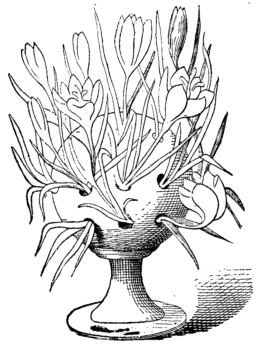
FIG. 4.—Crocus Flowering in a Perforated Pot.
Without mentioning Chinese shadows, how many cheap amusements there are that can be varied to infinity merely by various combinations of the fingers interlocked in diverse manners!
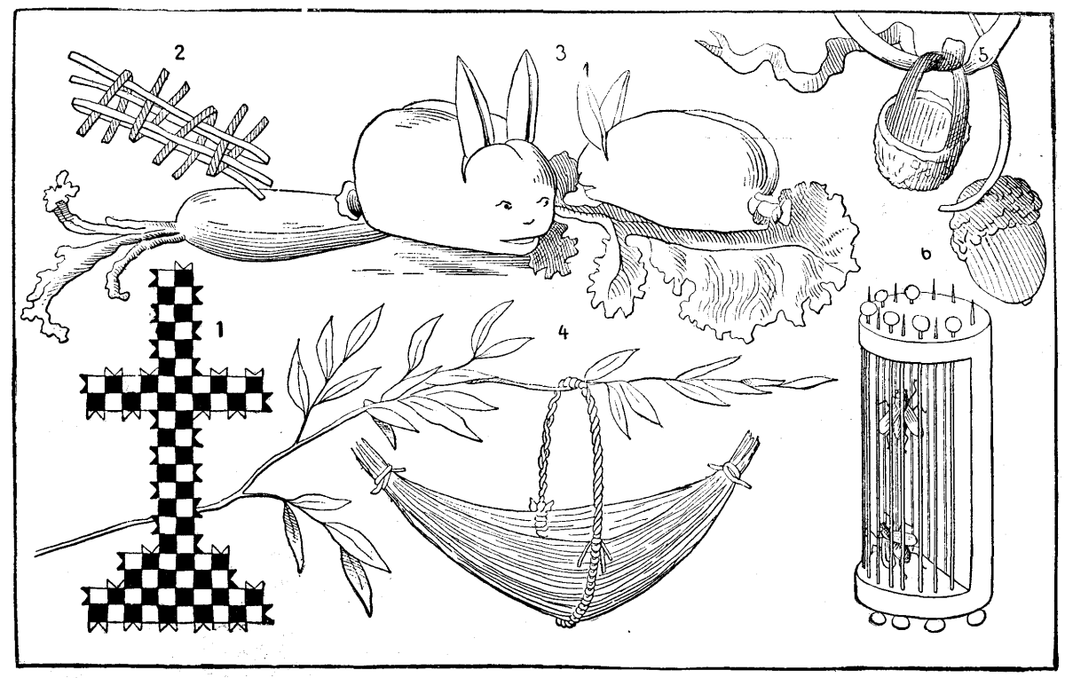
FIG. 5.—1. Paper Cross. 2. Method of Making the Cross. 3. Rabbits Made of Green Almonds. 4. Basket Made of Sedges. 5. Acorn Basket. 6. Fly-cage Made of aa Cork.">
All such amusements were much in vogue in former times, but we are assured that to-day mothers are less conversant with these curious and droll inventions, which were once transmitted like the tales of Mother Goose. They buy playthings for their children at great expense, and allow the latter to amuse themselves all by themselves. The toy paid for and given, the child is no longer in their mind. Those mothers who have preserved the traditions of these little pastimes, and know how to skillfully vary them, find therein so many resources for amusing their children. Then it is so pleasant to see the eyes of the latter eagerly fixed upon the scissors, and to hear their exclamations of pleasure and their fresh laughter when the paper is transformed under expert fingers into a boat, house, or what not!
FIG. 6.—The Lesson in Drawing.—An Illustrated Five-spot of Hearts.
It has required millions of mothers and nurses to put their wits to work to amuse their children in order to form that collection of charming combinations that at present constitutes a sort of science. Mr. Gaston Tissandier not long ago conceived the happy idea of bringing together in an illustrated volume a description of some of these improvised toys and amusing plays, and it is from this that the accompanying illustrations (which sufficiently explain themselves) are taken.
The Æolian harp is a musical instrument which is set in action by the wind. The instrument, which is not very well known, is yet very curious, and at the request of some of our readers we shall herewith give a description of it.
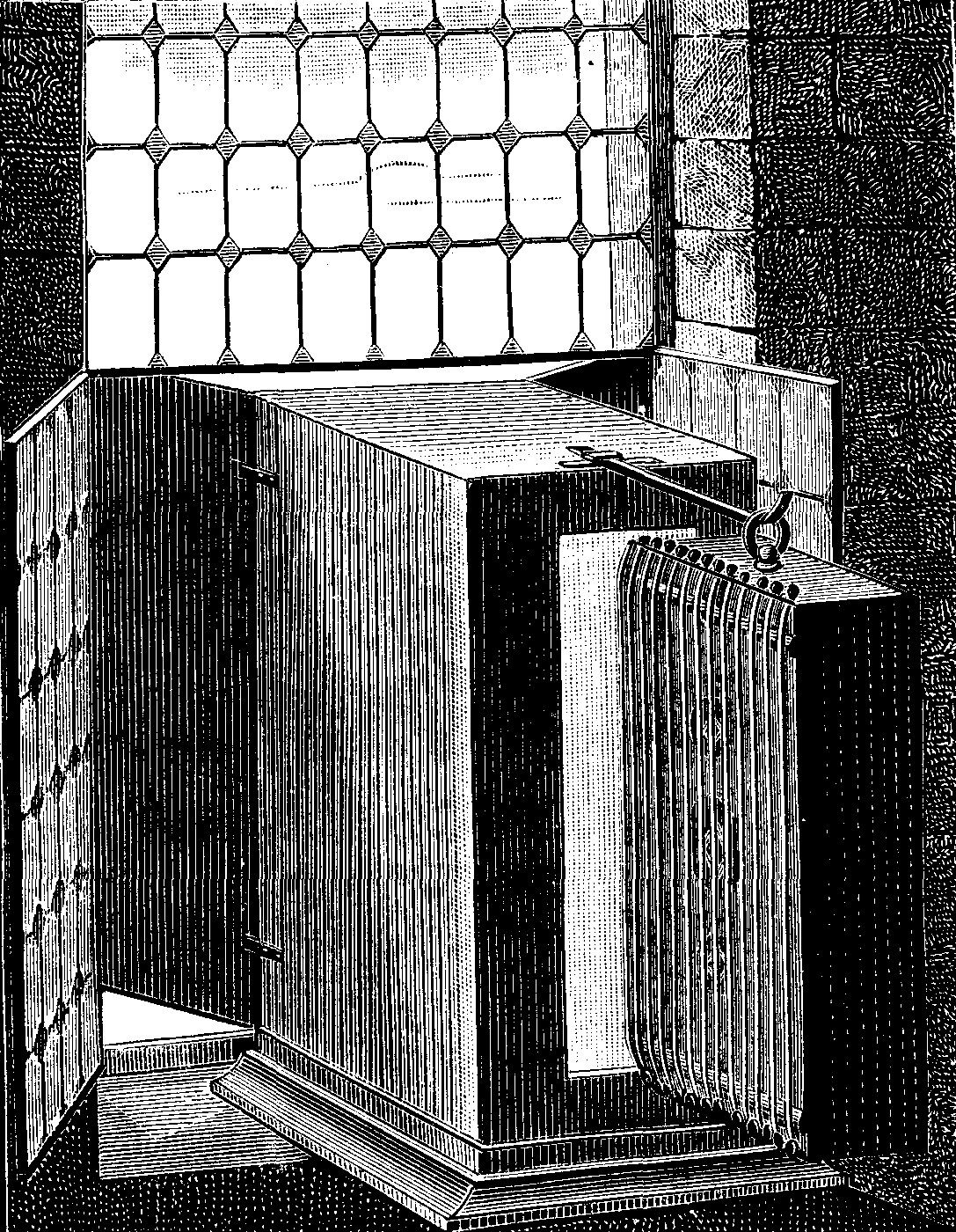
FIG. 1.—KIRCHER'S ÆOLIAN HARP.
According to a generally credited opinion, it is to Father Kircher, who devised so many ingenious machines in the seventeenth century, that we owe the first systematically constructed model of an Æolian harp. We must add, however, that the fact of the spontaneous resonance of certain musical instruments when exposed to a current of air had struck the observers of nature in times of remotest antiquity.
Without dwelling upon the history of the Æolian harp, we may say that in modern times this instrument has been especially constructed in England, Scotland, Germany, and Alsace. The Æolian harp of the Castle of Baden Baden, and those of the four turrets of Strassburg Cathedral are celebrated.
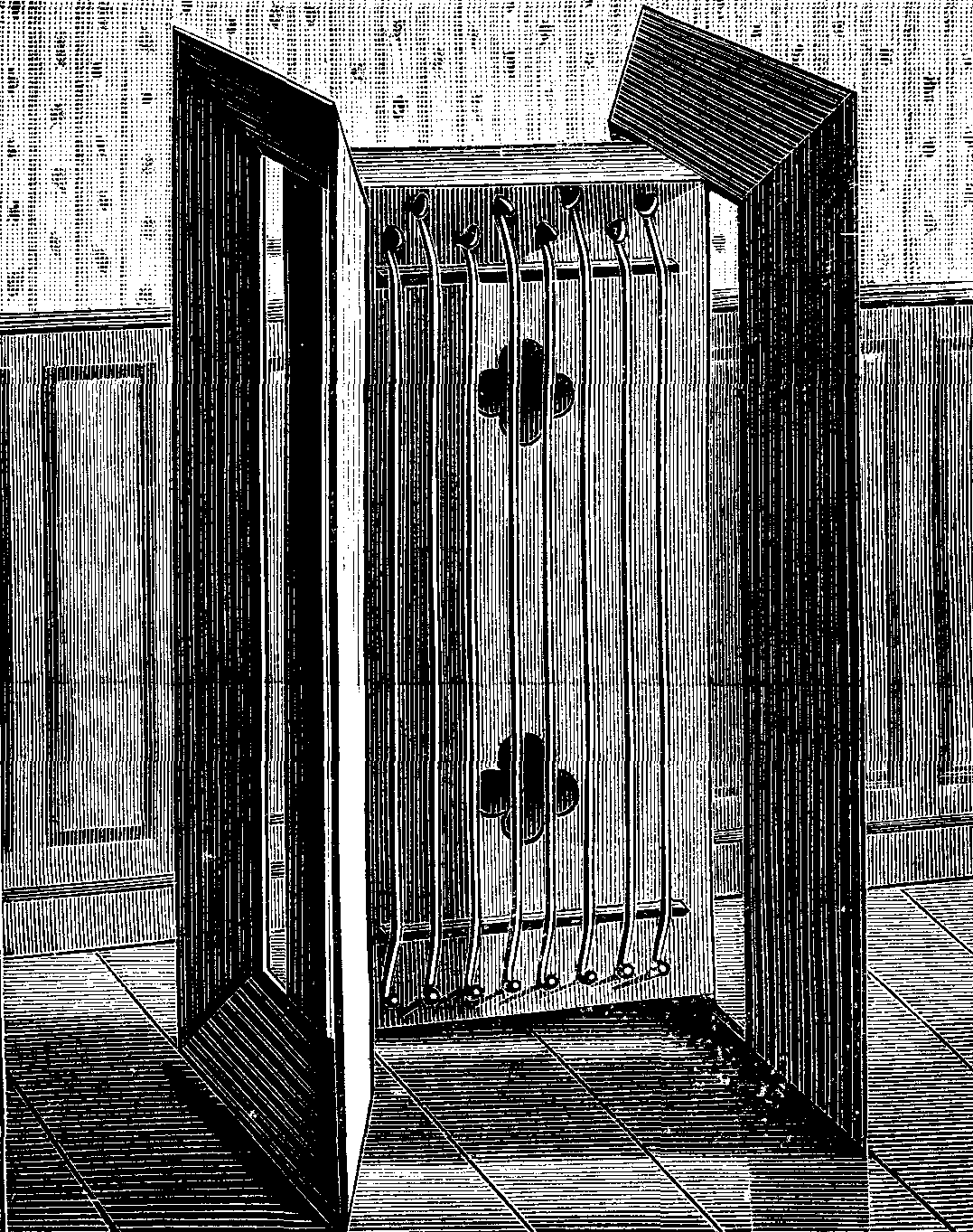
FIG. 2.—FROST & KASTNER'S IMPROVED ÆOLIAN HARP.
We shall first describe Kircher's harp, which this Jesuit savant constructed according to an observation made by Porta in 1558. The instrument consists of a rectangular box (Fig. 1), the sounding board of which, containing rose-shaped apertures, is provided with a certain number of strings stretched over two bridges and fastened to pegs at the extremities. This box carries a ring that serves for suspending it. Kircher recommends that the box be made of very sonorous fir wood, like that employed in the construction of stringed instruments. He would have it 1.085 meters in length, 0.434 meter in width, and 0.217 meter in height, and would provide it with fifteen catgut strings, tuned, not like those of other instruments to the third, fourth, or fifth, but all in unison or to the octave, in order, says he, that its sound shall be very harmonious. The experiments of Kircher showed him the necessity of employing a sort of concentrator in order to increase the force of the wind, and to obtain all the advantage possible from the current of air that was directed against the strings. The place where the instrument is located should not, according to him, be exposed to the open air, but must be a closed one. The air, nevertheless, must have free access to it on both sides of the harp. The force of the wind may be concentrated upon such a point in different ways; either, for example, by means of conical channels, or spiral ones like those used for causing sounds to reach the interior of a house from a more elevated place, or by means of a sort of doors. These latter, two in number, are adapted to a kind of receptacle made of boards and presenting the appearance of a small closet. In the back part of this receptacle there is a slit, and in front of this the harp is hung in a slightly oblique position. The whole posterior portion of the apparatus must be situated in the apartment, while the doors must remain outside the window (Fig. I). In later times the Æolian harp has been improved by Messrs. Frost and Kastner, whose apparatus is represented in Fig. 2. It consists of a rectangular box with two sounding boards, each provided with eight catgut strings. In order to limit the current of air and to bring it with more force against the strings, two wings are adapted near the thin surfaces opposed to the wind, so that the current may reach each group of cords on passing through the narrow aperture between the obliquely inclined wing and the body of the instrument. The dimensions of the resonant box are as follows: height, 1.28 meters; width, 0.27 meter; and thickness, 0.075 meter. Distance between the two bridges, or length of the sonorous portion of the cords, about 1 meter; width of the wings, 0.14 meter. Distance between the sounding board and the wings, 0.42 meter. Inclination of the wings, 50 degrees.
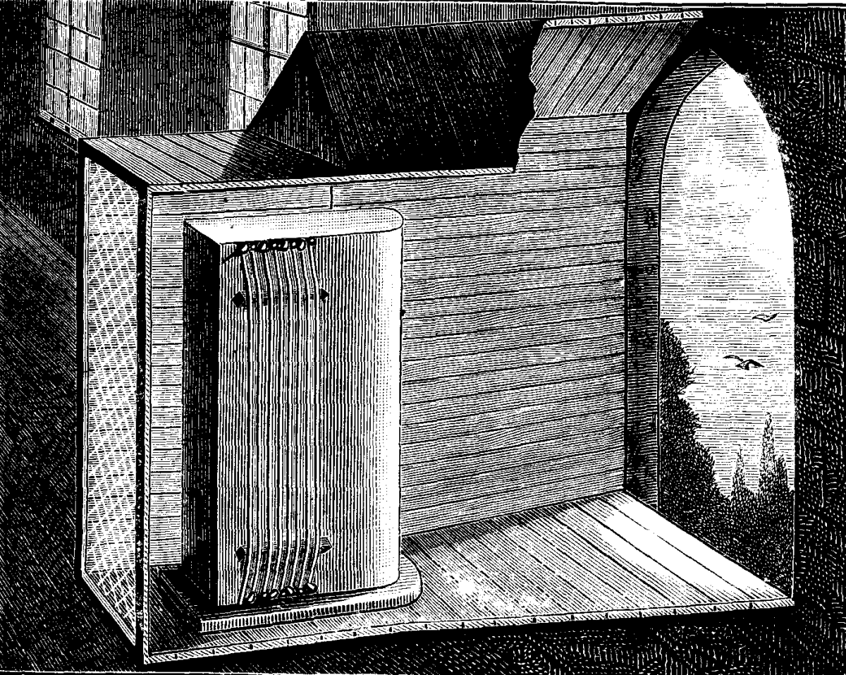
FIG. 3.—ÆOLIAN HARP IN THE OLD CASTLE OF BADEN BADEN.
The celebrated Æolian harps of the old castle of Baden Baden are entirely different, and merit description. One of them (Fig. 3) is formed of a resonant box, the construction of which differs from that of Æolian harps with a rectangular box, in that it is prolonged beyond the place occupied by the strings, and is rounded off behind. In the opposite side there are two long and narrow apertures. To prevent the apparatus from being injured by the weather, it is inclosed in a sort of case occupying the recess of the window in the old ruined castle in which it is exposed. Behind the harp there is a wire lattice door, the purpose of which seems to be to protect the instrument against the attempts of robbers or the indiscreet contact of tourists. We annex to the general view of the instrument a front and profile plan (Fig. 4). The Æolian harp has often inspired both writers of prose and poetry. Chateaubriand, in Les Natchez, compares its sounds to the magic concerts that the celestial vaults resound. Without attributing such effects to the instrument, it must be admitted that it possesses remarkable properties, which act upon the nervous system and cause very different impressions, according to the temperament of those who listen to its accords.
FIG. 4.—PLAN OF THE BADEN BADEN INSTRUMENT.
Hector Berlioz, in his Voyage Musicale en Italie, has given as follows the curious effects that an Æolian harp produced upon his lively and impassioned imagination: "On one of those gloomy days that sadden the end of the year, listen, while reading Ossian, to the fantastic harmony of an Æolian harp swinging at the top of a tree deprived of verdure, and I defy you not to experience a profound feeling of sadness and of abandon, and a vague and infinite desire for another existence."
An English physician, Dr. J.M. Cox, in his practical Observations upon dementia, asserts that unfortunate lunatics have been seen whose sensitiveness was such that ordinary means of cure had to be given up with them, but who were instantly calmed by the sweet and varied accords of an Æolian harp. Other observers narrate that they have heard the efficacy of Aeolian sounds spoken of in Scotland for producing sleep.
Telegraph wires are often, under the influence of the winds, submitted to vibrations which reproduce the phenomena of the Aeolian harp. The electric telegraph, which, before the construction of the Kehl bridge, directly traversed the Rhine, very frequently resounded, and the observer who placed his ear against the poles on the bank of the river was enabled to hear something like a far-off sound of bells.—La Nature.
FIG. 1.—PRODUCTION OF ILLUMINATING GAS.
Burn a piece of paper of about the size of the hand upon a clean porcelain plate, and this will serve to show the phenomena of carbonization and the formation of empyreumatic products under the action of heat. Under the burned paper there will be found a yellowish deposit which sticks to the fingers, and which consists of oil of paper produced by distillation. An idea of the production of illuminating gas through the distillation of coal may be easily given by means a single clay pipe. Upon filling the bowl of this with fragments of coal, closing the opening with clay, and, after the latter is dry, placing the bowl in a coal fire so that the stem shall project, gas will soon be observed issuing from, the latter, and, when lighted, will give a very bright flame. If the pipe seems to be a little too costly, recourse maybe had to a large piece of wrapping paper rolled into the form of a cornucopia, and held in the left hand by means of the pointed end. If, after an aperture has been made in this near the point, the base be lighted, the heat developed by the flame will produce a sort of distillation of the organic matter of the paper, and the empyreumatic and gaseous products will rise in the cone, and make their exit through the orifice, where they may be lighted with a match (Fig. 1). It goes without saying that this experiment lasts but a few seconds; but, as short as this period is, it is sufficient to give a demonstration of the production of illuminating gas through the distillation of organic matters. Care should be taken not to set anything on fire while performing it, and it is well to operate over a pavement, and far from any inflammable materials.
FIG. 2.—EXPERIMENT ON THE ELASTICITY OF BODIES.
Mould a piece of fresh bread with the fingers so as to give it the size and shape shown in Fig. 2. If this object be placed upon a wooden table, and a hard blow be given it with the fist, it will be found impossible to put it permanently out of shape. However hard be the blow, the elastic material, although flattened for an instant, will always resume its original form. If the object be thrown on the floor with all one's might, the result will be the same; its elasticity will always cause it to spring back to its original form. The experiment will only succeed when the bread that is used is very fresh and soft.
The Dance of the Electrified Puppets.—We have already pointed out a means of obtaining electrical manifestations without recourse to a machine, and shall now describe a very easily performed experiment—the dance of the electrified puppets.
FIG. 1.—DANCE OF THE ELECTRIFIED PUPPETS.
Procure a pane of glass about 10 inches in width and 14 in length, and support it between two large books, as shown in Fig. 1. The glass must be inserted in the books in such a way that it shall be an inch and a fraction above the surface of the table. Then, with a pair of scissors, cut out of a piece of tissue-paper a number of figures, such as men, women, clowns, frogs, etc. These little figures must not exceed three-quarters of an inch in length. We show some of actual size in Fig. 1. They may be cut out of papers of different colors, so as to give variety to the scene. After they are prepared they are to be placed in the ball-room, that is to say, in the space between the books, glass, and table. They should be laid flat upon the table, and alongside of one another. Now rub the upper surface of the glass vigorously with a piece of silk or woolen, and, in a few instants, the figures will be attracted by the electricity, and suddenly stand up straight and jump up to the transparent ceiling of their ball-room. Then they will be repelled, and again attracted, and thus keep up a lively dance. When the rubbing is stopped, the dance continues spontaneously for some little time, and even the contact of the hand suffices to animate the figures. In order that this experiment shall prove a success, the glass used must be very dry, as well as the fabric with which it is rubbed. If the latter be warmed, the manifestation will be more rapid and energetic. Silk answers better than woolen.
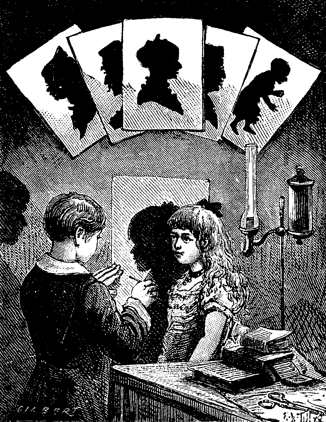
FIG. 2.—SILHOUETTE PORTRAITS.
Silhouette Portraits.—Take a large sheet of paper, black on one side and white on the other, and affix it to the wall, white surface outward, by means of pins or tacks. Place a very bright light upon the table, at a proper distance, and allow the person whose portrait it is desired to form to stand between it and the wall (Fig. 2). Then, with a pencil, draw the outlines of the shadow projected. While this is being done, it is very necessary that the subject shall keep perfectly immovable. When the outlines are sketched, remove the paper from the wall and cut out the portrait. After this, all that remains to be done is to turn the portrait over and paste it to a sheet of white paper. The silhouette is profiled in black, and if the operation be skillfully performed, the resemblance will be perfect.—La Nature.
Our readers have often seen grocers' clerks or employes of business houses break the string with which they had tied up a package, by seizing it with the hands, bringing the latter close together, and then suddenly separating them with a quick movement. If it be thought that this quick motion is sufficient, let any one try it, and he will merely cut his hands without breaking the string, provided the latter has some little strength. In order to succeed, the cord must be arranged in a certain manner, as we shall explain.
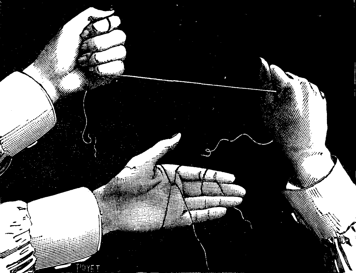
MODE OF BREAKING A CORD WITH THE HANDS.
The cord to be broken is placed upon the left hand, and one of its ends is passed over the other in such a way as to form a cross, and the end forming the shorter part of the cross is wound around the fingers (it should be left long enough to make several turns). The other end is then turned back and wound around the right hand, so as to leave a space of about eighteen inches between the latter and the left hand. If these directions are properly followed, the string should have the form of a Y in the middle of the hand, as shown in the lower figure of the accompanying engraving.
It is only necessary after this to close the hand, after seeing that the Y is very taut, and to seize the cord with the other hand, as shown in the upper figure. This done, the two hands are brought together and then suddenly separated so as to give a quick pull on the point of junction of the Y-shaped branches, which form a true knife. It will be readily seen that as the cord is broken suddenly the shock does not have time to transmit itself to the hands. This is an interesting demonstration of the principle of inertia.
The curious apparatus that we represent in Fig. 1, from an old English engraving of 1823, is an aquatic velocipede which was utilized with success during the entire winter of 1822. An amateur employed it for hunting ducks upon the numerous streams of Lincolnshire, and, as it appears, obtained very good results from it. The device is very ingenious. It consists of three floats of from 1,800 to 2,000 cubic inches capacity, made of copper or tin plate. These are full of air, and must be perfectly tight. They are held together by arched iron rods, as shown in the cut, so as to form the three angles of an isosceles triangle. These rods are provided in the center with a saddle for the velocipedist to sit upon. The apparatus floats upon the water and sustains the hunter, whose feet are provided with quite short paddles, by means of which he navigates, and steers himself.
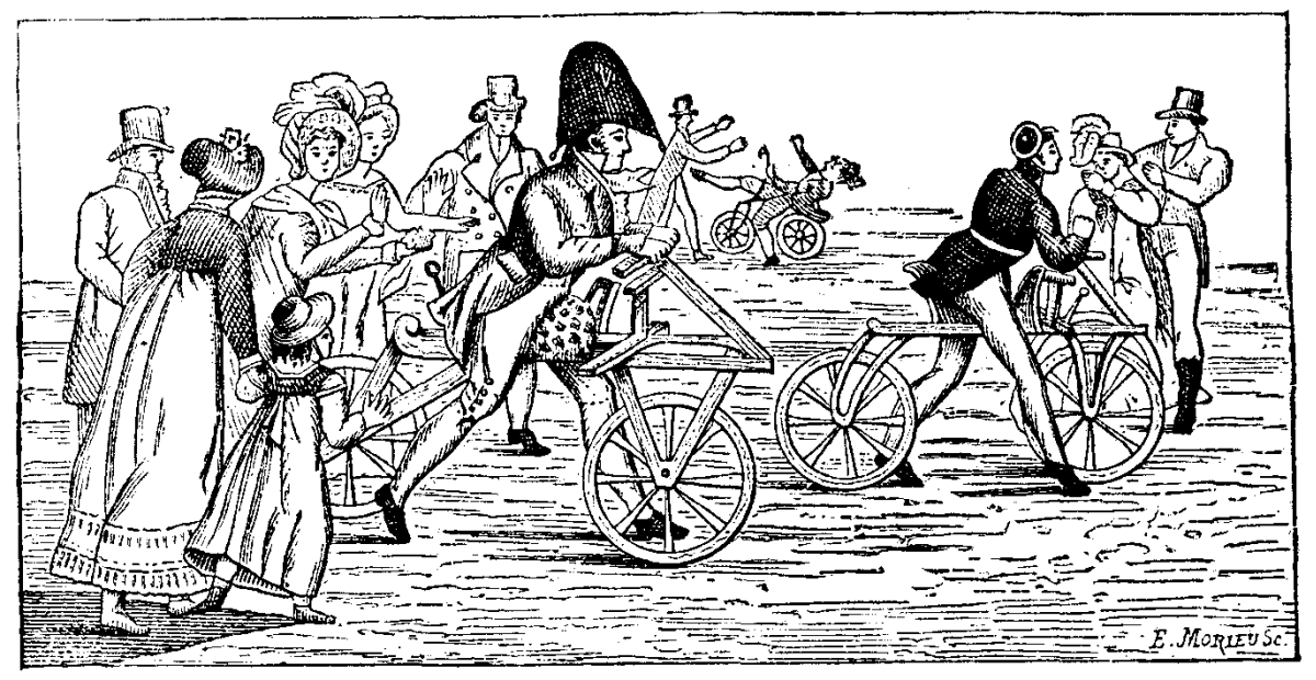
FIG. 1.—AN AQUATIC VELOCIPEDE OF 1822.
The amusing engraving of this velocipede, which is mentioned under the name of the aquatic tripod, puts us in mind of another document of the same kind that we have seen in the gallery of prints of the National Library. It is a naively drawn lithograph representing a trial of velocipedes in the Luxembourg Garden, at Paris, in 1818. In Fig. 2 we give a reduced copy of it. It will be seen that in 1818 velocipedes were made of wood and were provided with two wheels—one in front, and the other behind. The propelling was done by alternately placing the feet on the ground.
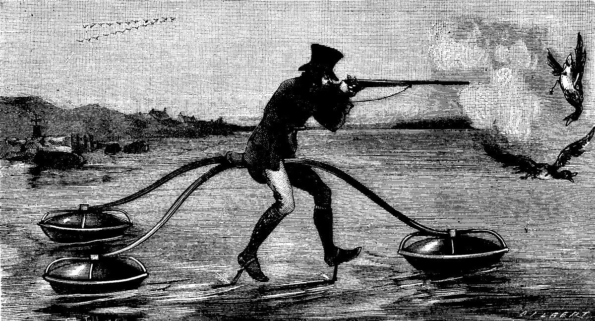
FIG. 2.—A TRIAL OF VELOCIPEDES IN 1818.
The apparatus is of simple construction. It consists of a glass sphere silvered inside and placed before the lens of a camera, the axis of the instrument being placed parallel to the polar axis of the earth. The whole arrangement will be readily understood by an inspection of Fig. 1. The light from the sun is reflected from the globe, and some of it, passing through the lens, forms an image on a piece of prepared paper within the camera. In consequence of the rotation of the earth, the image describes an arc of a circle on the paper, and when the sun is obscured, this arc is necessarily discontinuous. The image is not a point, but a line, and in certain relative positions of the sphere, lens, and paper, the line is radial and very thin, so that the obscuration of the sun for only one minute is indicated by a weakening of the image.
FIG. 1.
In the actual apparatus the sphere is an ordinary round-bottomed flask about 95 mm. in diameter, and the lens a simple double convex lens of about 90 mm. focal length. The sensitive paper employed is the ordinary ferro-prussiate now so much used by engineers for copying tracings. This was selected in consequence of the ease with which the impression is fixed, for the paper merely requires to be washed in a stream of water for six minutes, no chemicals being necessary. When the paper is dry, radial lines containing between them angles of 15° are drawn from the center of the circular impression, and thus give the hour scale, the time of apparent noon being of course given by a line passing through the plan of the meridian. Fig. 2 is a copy of the record of June 27, 1884; in the morning the sun shone brightly, toward noon clouds began to form, and in the afternoon the sky was hazy. The field in which the instrument is placed is surrounded by trees, so the ends of the trace are cut off sharply by shadows.
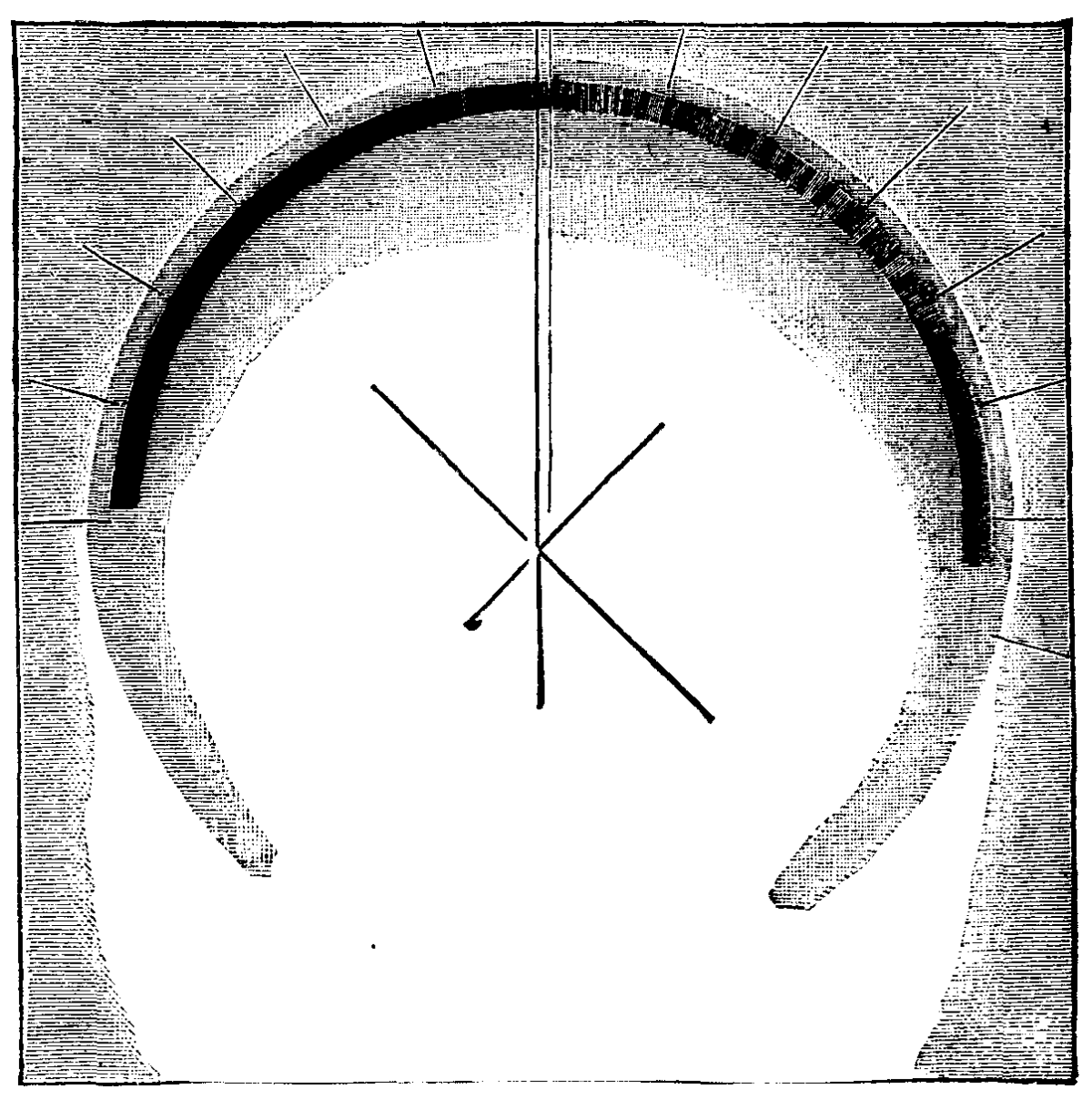
FIG. 2.
With the alteration of declination of the sun, the light entering the camera is reflected from different portions of the sphere, and an alteration of the position of the focus results. This may be corrected in three ways; by moving (1) the paper, (2) the lens, or (3) the sphere. In the present apparatus the first method has been adopted, and now the camera is about twice as long as it was in June. As a consequence, the circular image is enlarged, and the light therefore weakened, and that at a time of year when it can least be spared. If the focus is altered by moving the lens, the winter circle is small and the summer circle is much larger. This would perhaps be too much to the advantage of the winter sun. If, however, the lens and paper are maintained at a constant distance, and the sphere alone moved, the circles are more nearly of the same diameter throughout the year, the winter one still remaining the smallest. This seems, therefore, to be the most advantageous arrangement, and the one that will be adopted in future. It may be possible also to find positions for the sphere, lens, and paper such that the intensity of the image is a true measure of the intensity of the sun's light; at present, however, this has not been done, the want of sunlight and the press of official work having prevented the carrying out of the necessary experiments. A more sensitive paper might also be used with advantage, and in observatories where photographic processes are carried on daily there would be no difficulty on this score, but my principal object was to devise some economical instrument requiring only easy manipulation, so that at a considerable number of places the instruments might be set up, giving a more useful average of the duration of sunshine than can be obtained from only a few stations. The instrument also gives a record when the sun is shining through light clouds; in this case the image is somewhat blurred and naturally weakened, and it may be difficult or impossible to employ any scale for measuring the intensity under such conditions, but it must be remembered that, even when the sun is shining in this imperfect manner, it is really doing work on the vegetation of the earth, and deserves to be recorded.
It may be well to say that the instrument is in no way protected. Some friends, whose opinion I highly value, urged me to patent it; but as I strongly hold the view that the work of all students of science should be given freely to the world, the apparatus was described at the Physical Society a few hours after the advice was given, lest the greed of filthy lucre should, on further deliberation, cause me to act contrary to my principles.—Herbert McLeod, Nature.
In the limestone mountains of the Austrian Alpine countries, numerous large caverns and caves are found, some of which are several miles long. They have been formed by the raising, lowering, and sliding of the layers of sand, or washed out by the stream.
In one of these caverns near Peggau, in Styria, Austria, the skeleton of a bear (Ursus Spelaeus) and the skull of another bear of the same kind were found, both of which are shown in the annexed cut taken from the Illustrirte Zeitung, the detached skull being placed on a board. The place in which these bones were found had never been reached before, as the skeleton was covered by a layer, from four to six inches thick, of stalagmites, which in turn rested on a layer of pieces or chips of bones and carbonate of lime, sand, etc. The bones of the skeleton were scattered over a space about eight square yards, and it required several days' work to remove the layers from the bones by means of a mallet and chisel and to give the bones, etc., a presentable appearance.
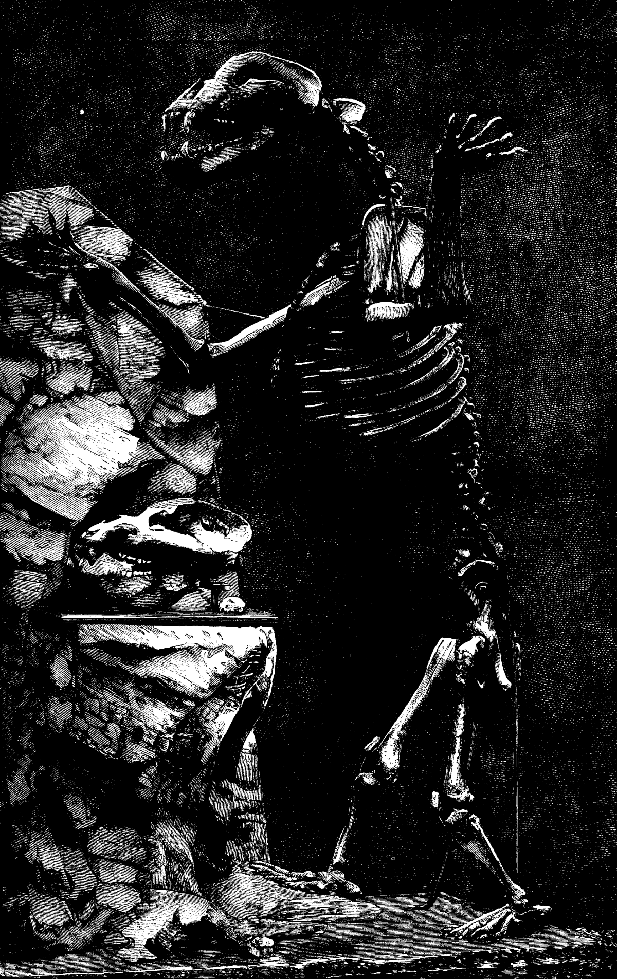
SKELETON OF A BEAR FOUND IN A CAVE IN STYRIA, AUSTRIA.
The skull on the board is of especial interest on account of the beautiful crystals of calcareous spar, which are from 1/10 to 1/4 of an inch long, and are formed on the inner sides of the skull. The skull is 5-1/2 in. wide between the fangs and 6-3/5 in. wide at the forehead, whereas the skull of the skeleton is only 3-9/10 in. wide at the fangs and 5-1/10 in. wide at the forehead. The skull of the skeleton is 22 in. long. The small white object on the board supporting the detached skull represents the skull of an ordinary cat, thus giving an idea of the enormous size of the bear's skull. The skeleton is 9 ft. 8 in. high, and is one of the largest and most complete that has been found.
The German Verein zur Bedförderung des Gewerbefleisses offers the following, among other prizes, for essays on technical subjects: One thousand marks (£50) for a comparative examination of the various methods hitherto used for determination of the hardness of metals, with an exposition of their sources of error and limits of accuracy. It is stated, as a reason for offering the prize, that the methods for making the required tests are but yet little developed, and that no thorough comparison has yet been made of the various methods. The hardness of metals and alloys being a very important factor in several processes, a really good method of determination is highly desirable. Three thousand marks (£150) for the best essay on the resistance to pressure of iron work in buildings, at increased temperatures. It appears that after a certain fire in a manufactory at Berlin, the police authorities issued notices concerning the use of cast-iron columns in high buildings, and that these notices encountered great opposition in many quarters, as it was considered that neither practice nor theory had yet shown any proof that cast iron is less trustworthy than wrought iron in cases of fire.
A brilliant black varnish for iron, stone, or wood can be made by thoroughly incorporating ivory black with common shellac varnish. The mixture should be laid on very thin. But ordinary coal tar varnish will serve the same purpose in most cases quite as well, and it is not nearly so expensive.
Although the racing of steam yachts as a recognized sport has not made the progress that was at one time expected, yet the owner and crew of a crack vessel will take as much interest in her performance as those belonging to a sailing yacht, and hate to be passed quite as badly. In this way many informal matches come off, and some of these are for considerable distances. The Field contains a notice of a run recently made from Plymouth Breakwater to Gibraltar, by the Juno, owned by Mr. Frank Millan, and the Queen of Palmyra, in which the former beat the latter by only five minutes. The time occupied was four days twenty hours, a fair, though not extraordinary, performance for vessels of this size. The Juno has always been considered a slow boat, but has been much improved lately by new machinery, which has been put in her by Messrs. Day, Summers & Co. Her best performance on the run was 235 knots in 21¾ hours. The Marchesa, Mr. C.T. Kettlewell, started from Plymouth on the 23d of last December, and made the run to Gibraltar in four days seventeen hours; while the Amy, starting on December 12, was four days thirteen hours from Cowes to Gibraltar.
A catalogue, containing brief notices of many important scientific papers heretofore published in the SUPPLEMENT, may be had gratis at this office.
Sent by mail, postage prepaid, to subscribers in any part of the United States or Canada. Six dollars a year, sent, prepaid, to any foreign country.
All the back numbers of THE SUPPLEMENT, from the commencement, January 1, 1876, can be had. Price, 10 cents each.
All the back volumes of THE SUPPLEMENT can likewise be supplied. Two volumes are issued yearly. Price of each volume, $2.50, stitched in paper, or $3.50, bound in stiff covers.
COMBINED RATES—One copy of SCIENTIFIC AMERICAN and one copy of SCIENTIFIC AMERICAN SUPPLEMENT, one year, postpaid, $7.00.
A liberal discount to booksellers, news agents, and canvassers.
MUNN & CO., Publishers,
361 Broadway, New York, N.Y.
In connection with the Scientific American, Messrs. MUNN & Co. are Solicitors of American and Foreign Patents, have had 40 years' experience, and now have the largest establishment in the world. Patents are obtained on the best terms.
A special notice is made in the Scientific American of all Inventions patented through this Agency, with the name and residence of the Patentee. By the immense circulation thus given, public attention is directed to the merits of the new patent, and sales or introduction often easily effected.
Any person who has made a new discovery or invention can ascertain, free of charge, whether a patent can probably be obtained, by writing to MUNN & Co.
We also send free our Hand Book about the Patent Laws, Patents, Caveats. Trade Marks, their costs, and how procured. Address
MUNN & CO., 361 Broadway, New York.
Branch Office, cor. F and 7th Sts., Washington, D.C.