Advertisement: David Bridge & Co., LTD.
Advertisement: David Bridge & Co., LTD.
Advertisement: Fairbairn, Lawson Combe Barbour, LTD.
Advertisement: Robert Hall & Sons
Advertisement: A. F. Craig & Co., LTD.
Advertisement: Urquhart, Lindsay & Co., LTD.
Advertisement: H. Smethurst & Sons, LTD.
Advertisement: White, Milne & Co.
Advertisement: Thomas C. Keay, LTD.
Advertisement: Robert Stiven & Co.
Advertisement: Pitman's Commodities and Industries Series
Advertisement: George Hattersley & Sons, LTD.
The sub-title of this little volume indicates that practically all the processes involved in the cultivation of jute plants, the extraction of the fibre, and the transformation of the fibre into useful commodities, have been considered. In addition, every important branch of this wide industry is liberally illustrated, and the description, although not severely technical, is sufficiently so to enable students, or those with no previous knowledge of the subject, to follow the operations intelligently, and to become more or less acquainted with the general routine of jute manufacture. As a matter of fact, the work forms a medium of study for textile students, and a suitable introduction to the more detailed literature by the authors on these textile subjects.
T. WOODHOUSE.
P. KILGOUR.
March, 1921.
Advertisement: J. M. Adam & Co.
Advertisement: Advertisement: James F. Low & Co.,
LTD.
The five main fibres used for ordinary textile purposes are cotton, flax, jute, silk and wool; in this group jute has been considered in general as being of the least value, not only in regard to price, but also in regard to utility. It is only under phenomenal conditions which arise from a great upheaval such as that which took place during the world's great war from 1914 onwards that, from a commercial point of view, the extreme importance of the jute fibre and its products are fully realized. Millions of sand bags were made from the year 1914 to the year 1918 solely for military purposes, while huge quantities of jute cloth were utilized as the covering material for food stuffs of various kinds, thus liberating the other textile fibres and cloth for equally important purposes. It is on record that in one short period of fourteen days, 150,000,000 sand-bags were collected, packed and despatched from Dundee to be used as protective elements in various ways and seats of conflict.
A glance into the records of the textile industries will reveal the fact that the jute fibre was practically unknown in these islands a hundred years ago. Unsuccessful attempts were certainly made to import the fibre into Great Britain in the latter part of the 18th century, and it has been used in India for centuries in the making of cord, twine and coarse fabrics, because the fibre is indigenous to that country. And since all the manufacturing methods there, for a considerable time were manual ones, the industry--if such it could be called--moved along slowly, providing employment only for the needs of a small section of the community on the Eastern shores.
The first small imports of jute fibre were due to the instigation of Dr. Roxburgh and the East India Company, but it was only after repeated requests that any attempt was made to utilize the samples of jute for practical experiments The fibre was so unlike any of the existing staples that those interested in textiles were not anxious to experiment with it, but ultimately they were persuaded to do so; these persistent requests for trials, and the interest which was finally aroused, formed the nucleus of the existing important jute industry.
Apart from the above-mentioned efforts, the introduction of the jute fibre into Great Britain was delayed until 1822, when the first small consignment reached Dundee--now the Western home of the jute industry. This quantity was imported into this country with the special object of having it treated by mechanical means, much in the same way as flax fibre was being treated. At this period Dundee was a comparatively important textile centre in regard to the spinning and weaving of flax and hemp; it was, in consequence, only natural that the longer, but otherwise apparently similar and coarser, jute fibre should be submitted to the machinery in vogue for the preparation and spinning of flax and hemp. When we say similar, we mean in general appearance; it is now well-known that there is a considerable difference between jute fibre and those of hemp and flax, and hence the modifications in preparation which had ultimately to be introduced to enable the jute fibre to be successfully treated. These modifications shall be discussed at a later stage.
It might be stated that while only 368 cwt. of jute fibre was reported as being shipped from Calcutta to this country in 1828, the imports gradually increased as time passed on. The yarns which were made from the fibre were heavier or thicker than those in demand for the usual types of cloth, and it was desirable that other types of cloth should be introduced so that these yarns could be utilized. About the year 1838, representatives of the Dutch Government placed comparatively large orders with the manufacturers for jute bags to be used for carrying the crop of coffee beans from their West Indian possessions. The subsequent rapid growth of the industry, and the demand for newer types of cloth, are perhaps due more to the above fortunate experiment than to any other circumstance.
By the year or season 1850-51, the British imports of jute fibre had increased to over 28,000 tons, and they reached 46,000 tons in the season 1860-61. Attention meanwhile had been directed to the possibility of manufacturing jute goods by machinery in India--the seat of the cultivation and growth of the fibre. At least such a probability was anticipated, for in the year 1858 a small consignment of machinery was despatched to Calcutta, and an attempt made to produce the gunny bags which were typical of the Indian native industry.
The great difference between the more or less unorganized hand labour and the essential organization of modern mills and factories soon became apparent, for in the first place it was difficult to induce the natives to remain inside the works during the period of training, and equally difficult to keep the trained operatives constantly employed. Monetary affairs induced them to leave the mills and factories for their more usual mode of living in the country.
In the face of these difficulties, however, the industry grew in India as well as in Dundee. For several years before the war, the quantity of raw jute fibre brought to Dundee and other British ports amounted to 200,000 tons. During the same period preceding the war, nearly 1,000,000 tons were exported to various countries, while the Indian annual consumption--due jointly to the home industry and the mills in the vicinity of Calcutta--reached the same huge total of one million tons.
The growth of the jute industry in several parts of the world, and consequently its gradually increasing importance in regard to the production of yarns and cloth for various purposes, enables it to be ranked as one of the important industries in the textile group, and one which may perhaps attain a much more important position in the near future amongst our national manufacturing processes. As a matter of fact, at the present time, huge extensions are contemplated and actually taking place in India.
Botanical and Physical Features of the Plant. Jute fibre is obtained from two varieties of plants which appear to differ only in the shape of the fruit or seed vessel. Thus, the fruit of the variety Corchorus Capsularis is enclosed in a capsule of approximately circular section, whereas the fruit of the variety Corchorus Olitorius is contained in a pod. Both belong to the order Tiliacea, and are annuals cultivated mostly in Bengal and Assam.
Other varieties are recorded, e.g. the Corchorus Japonicus of Japan, and the Corchorus Mompoxensis used in Panama for making a kind of tea, while one variety of jute plant is referred to in the book of job as the Jew's Mallow; this variety C. Olitorius, has been used in the East from time immemorial as a pot herb.
The two main varieties C. Capsularis and C. Olilorius are cultivated in Bengal for the production of fibre, while for seed purposes, large tracts of land are cultivated in Assam, and the seeds exported for use principally in Mymensingh and Dacca.
The above two varieties of the jute plant vary in height from 5 to 15 feet, and, in a normal season, reach maturity in about four months from the time of sowing. In some districts the stems of jute plants are sometimes rather dark in colour, but, in general, they are green or pink, and straight with a tendency to branch. The leaves are alternate on the stems, 4 to 5 inches in length, and about 1-1/2 inches in breadth with serrated edges. Pale yellow flowers spring from the axil (axilla) of the leaves, and there is an abundance of small seeds in the fruit which, as mentioned, is characteristic of the variety.
While many attempts have been made to cultivate jute plants in various parts of the world, the results seem to indicate that the necessary conditions for the successful cultivation of them are completely fulfilled only in the Bengal area, and the geographical position of this province is mainly responsible for these conditions. On referring to a map of India, it will be seen that Bengal is directly north of the bay of that name, and is bounded on the north by the great Himalayan mountains.
During the winter period when the prevailing winds are from the north, large areas of the mountainous regions are covered with snow, but when the winds change and come from the south, and particularly during the warmer weather, the moist warm air raises the general temperature and also melts much of the snow on the mountain tracts. The rain and melted snow swell the two great rivers on the east and west of Bengal--the Patna and the Brahmaputra--and the tremendous volume of water carries down decayed vegetable and animal matter which is ultimately spread on the flat areas of Bengal as alluvial deposits, and thus provides an ideal layer of soil for the propagation of the jute plants.
The cultivation of land for the growing of jute plants is most extensively conducted in the centres bordering on the courses of the rivers, and particularly in Mymensingh, Dacca, Hooghly and Pabna, and while 90 per cent. of the fibre is produced in Bengal, Orissa and Bihar, there is 10 per cent. produced outside these areas.
The Corchorus Capsularis variety is usually cultivated in the higher and richer soils, while the Corchorus Olitorius variety is most suited for the lower-lying alluvial soils, and to the districts where the rainfall is irregular; indeed, the C. Olitorius may be grown in certain other districts of India which appear quite unsuitable for the C. Capsularis.
The farming operations in India are rather simple when compared with the corresponding operations in this country; there is evidently not the same necessity for extensive working of the Indian soil as there is for the heavier lands; another reason for the primitive Eastern methods may be the absence of horses.
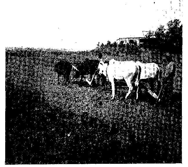
The ploughs are made of wood and faced with iron. Bullocks, in teams of two or more, are harnessed to the plough as shown in Fig. 1 where a field is being ploughed as a preliminary process in jute cultivation. The bullocks draw the plough in much the same way as horses do in this country.
The operation of ploughing breaks up the soil, while the rough clods may be broken by hand mallets or by the use of the "hengha"--a piece of tree boll harnessed at the ends to a pair of bullocks.
The breaking up of the land prepares it for the cleaning process which is performed by what are termed "ladders"; these ladders are made of a few bamboos fixed cross-wise and provided with projecting pins to scratch or open the soil, and to collect the roots of the previous crop; they are the equivalent of our harrows, and may be used repeatedly during the winter and spring seasons so that a fine tilth may be produced.
When manure is essential, it is applied in the later ploughings, but other large areas have artificial or chemical manures added at similar stages in the process. Farm-yard manure is preferred, but castor-cake and the water hyacinth--a weed--constitute good substitutes.
After the soil has been satisfactorily prepared, the seed is sown by hand at the period which appears most suitable for the particular district. The usual sowing time is from February to the end of May, and even in June in some districts where late crops can be obtained.
There are early and late varieties of the plants, and a carefully judged distribution of the varieties of seed over the districts for the growing period will not only yield a succession of crops for easy harvesting, but will also help the farmer in the selection of seeds for other areas where atmospheric conditions differ.
It is a good practice, where possible, to sow the seed in two directions at right angles to each other, and thus secure as uniform a distribution as possible. The amount of seed used depends partly upon the district, and in general from 10 lbs. to 30 lbs. per acre are sown. The seed may cost about 8 annas or more per ser (about 2 lbs.).
Plants should be specially cultivated for the production of seed in order to obtain the best results from these seeds for fibre plants. Many of the ryots (farmers) use seed which has been collected from plants grown from inferior seed, or from odd and often poor plants; they also grow plants year after year on the same soil. The fibres obtained, as a rule, and as a result of this method of obtaining seeds, gradually deteriorate; much better results accrue when succession of crops and change of seed are carefully attended to.
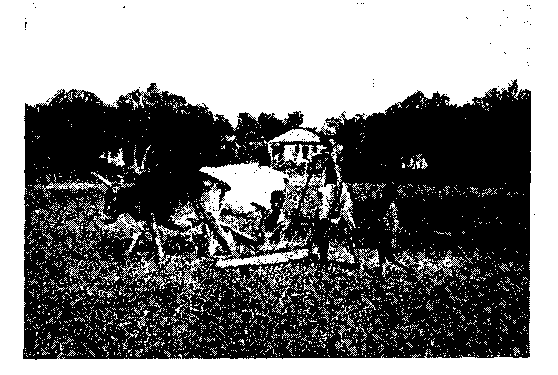
If the weather conditions are favourable, the seeds will germinate in 8 to 10 days, after which the plants grow rapidly. The heat and showers of rain combined soon form a crust on the soil which should be broken; this is done by means of another ladder provided with long pins, and Fig. 2 illustrates the operation in process. This second laddering process opens up the soil and allows the moisture and heat to enter. The young plants are now thinned, and the ground weeded periodically, until the plants reach a sufficient height or strength to prevent the words from spreading.
The space between the growing plants will vary according to the region; if there is a tendency to slow growth, there is an abundance of plants; whereas, the thinning is most severe where the plants show prospects of growing thick and tall.
In a normal season the plants will reach maturity in about 3 1/2 to 4 months from the time of sowing. Although different opinions are held as to the best time for harvesting, that when the fruits are setting appears to be most in favour; plants harvested at this stage usually yield a large quantity of good fibre which can be perfectly cleaned, and which is of good spinning quality.
The plants are cut down by hand and with home-made knives; in general, these knives are of crude manufacture, but they appear to be quite suitable for the purpose. A field of jute plants ready for cutting will certainly form a delightful picture, but the prospect of the operation of cutting indicates a formidable piece of work since it requires about 10 to 14 tons of the green crop to produce about 10 to 15 cwt. of clean dry fibre.
The method of separating the bast layer (in which the fibres are embedded) from the stem of the plant requires a large supply of water, since the plants must be completely submerged in the water for a period varying from 8 to 30 days; such time is dependent upon the period of the year and upon the district in which the operation is performed.
The above operation of detaching the bast layer from the stem is technically known as "retting," and a good type of retting or steeping place is an off-set of a run, branch, or stream where the water moves slowly, or even remains at rest, during the time the plants are under treatment.
The disintegration of the structural part of the plant is due to a bacterial action, and gas is given off during the operation. The farmer, or ryot, and his men know what progress the action is making by the presence of the air bells which rise to the surface; when the formation of air bells ceases, the men examine the plants daily to see that the operation does not go too far, otherwise the fibrous layer would be injured, and the resulting fibre weak. The stems are tested in these examinations to see if the fibrous layer, or bast layer, will strip off clean from the wood or stem. When the ryot considers that the layers are separated from the core sufficiently easy, the work of steeping ceases, and the process of stripping is commenced immediately. This latter process is conducted in various ways depending upon the practice in vogue in the district.
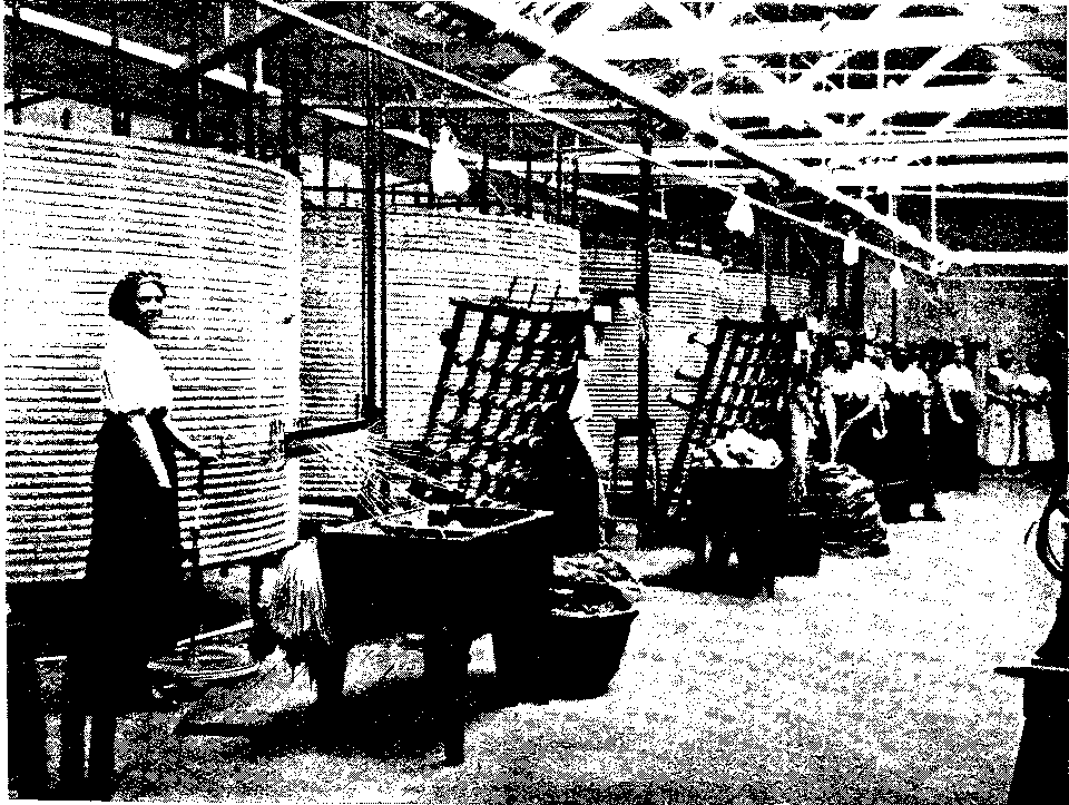
In one area the men work amongst the water breaking up the woody structure of the retted plants by means of mallets and cross rails fixed to uprights in the water; others break the stems by hand; while in other cases the stems are handed out of the water to women who strip off the fibrous layer and preserve intact the central core or straw to be used ultimately for thatching. The strips of fibre are all cleaned and rubbed in the water to remove all the vegetable impurities, and finally the fibre is dried, usually by hanging it over poles and protecting it from the direct rays of the sun.
If the water supply is deficient in the vicinity where the plants are grown, it may be advantageous to convey the fibrous layers to some other place provided with a better supply of water for the final washing and drying; imperfect retting and cleaning are apt to create defects in the fibre, and to cause considerable trouble or difficulties in subsequent branches of the industry.
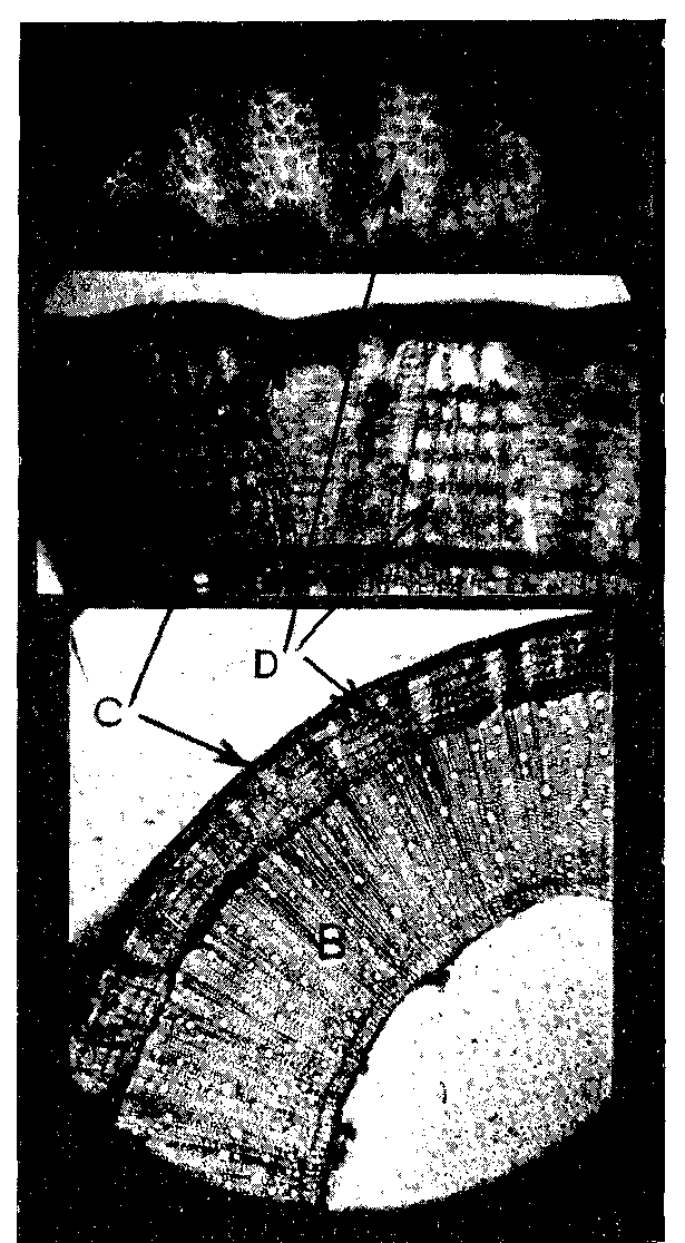
Fig. 3 illustrates photomicrographs of cross sections of a jute plant. The lower illustration represents approximately one quarter of a complete cross section. The central part of the stem or pith is lettered A; the next wide ring B is the woody matter; the outer covering or cuticle is marked C; while the actual fibrous layer appears between the parts B and C, and some of the fibres are indicated by D. The arrows show the corresponding parts in the three distinct views. The middle illustration shows an enlarged view of a small part of the lowest view, while the upper illustration is a further enlarged view of a small section of the middle view. It will be seen that each group of fibres is surrounded by vegetable matter.
Another method of stripping the fibrous layer off the stems or stalks, and one which is practised in certain districts with the object of preserving the straws, consists in breaking off a small portion, say one foot, at the top end of the stem; the operative then grasps the tops by the hand and shakes the plants to and fro in the water, thus loosening the parts, after which the straws float out, leaving the fibrous layer free. The straws are collected for future use, while the fibre is cleaned and washed in the usual way.
The Indian raw jute trade is conducted under various conditions. The method of marketing may be of such a nature that the farmers in some districts may have to make a rough assortment of the fibre into a number of qualities or grades, and these grades are well known in the particular areas; on the other hand, the farmers may prefer to sell the total yield of fibre at an overhead price per maund. A maund is approximately equal to 8 lbs., and this quantity forms a comparatively small bundle. In other cases, the fibre is made up into what is known as a "drum"; this is a hand-packed bale of from 1 1/2 to 3 or 3 1/2 maunds; it is a very convenient size for transit in India.
Practically one half of the total jute crop, of 9 to 10 million bales of 400 lbs. each, is used in India, and the remaining half is baled for export to the various parts of the world; a little over one million bales are exported annually to Great Britain, the bulk of this fibre comes to Dundee.
It is practically impossible for foreign purchasers to see the material at the assorting stations, but the standardized method of assorting and grading enables a purchaser to form a very good idea of the quality of the fibre, and its suitability or otherwise for special types of yarn and cloth. Thus, a form of selecting and grading has been established on a basis that provides a very large amount of jute each year of a quality which is known as "a first mark." A mark, in general, in reference to fibre, is simply some symbol, name, letter, monogram or the like, or a combination of two or more, oft-times with reference to some colour, to distinguish the origin of the fibre, the baler, or the merchant.
In normal years there is also a large quantity of fibre of a better quality than what is known as "first mark," and this better quality is termed "fine jute"; while there is yet a further lot, the quality of which is below these good ones. Since there are hundreds of different marks which are of value only to those connected directly with the trade, it is unnecessary to dwell on the subject. The following list, however, shows quotations of various kinds, and is taken from the Market Report of the Dundee Advertiser of March, 1920. The price of jute, like almost everything else, was at this date very high, so in order to make comparisons with the 1920 and normal prices, we introduce the prices for the corresponding grade, first marks, for the same month in the years 1915 onwards.
     JUTE PRICES, IN MARCH
          First Marks


   Year.       Price per ton.


          £. s. d.      £. s. d.
  1915    27         to 35 15
  1916    44
  1917    42 10
  1918    51
  1919    49
  1920    70        (spot)
It is necessary to state that the assorting and balings are generally so uniform that the trade can be conducted quite satisfactorily with the aid of the usual safeguards under contract, and guarantees regarding the properties of the fibre.
After these assorting operations are completed, the jute fibre is made up into bundles or "bojahs" of 200 lbs. each, and two of these 200 lb. bundles are subsequently made up into a standard bale, the weight of which is 400 lbs. This weight includes a permitted quantity of binding rope, up to 6 lbs. in weight, while the dimensions in the baling press of the 400 lb. bale are 4'1" X 1'6" X 1' 4".
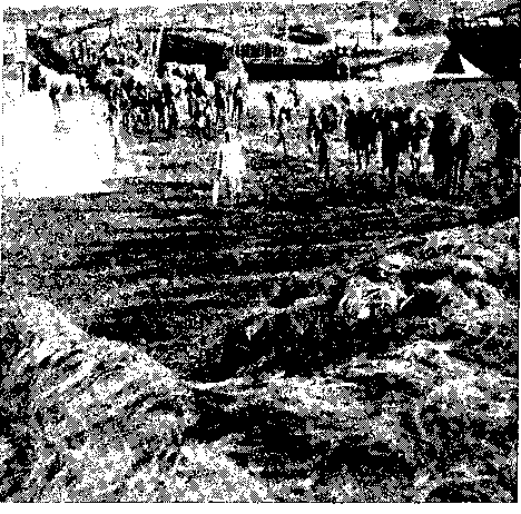
Large quantities of the smaller and loosely-packed bales are conveyed from the various places by boats to the baling houses or press houses as they are termed. These are very large establishments, and huge staffs of operatives are necessary to deal rapidly and efficiently with the large number of bales. In Fig. 4 scores of natives, superintended by a European, are seen carrying the smaller bales on their heads from the river boat to the press house. It is, of course, unnecessary to make the solid 400 lb. bales for Indian consumption; this practice is usually observed only for jute which is to be exported, and all such bales are weighed and measured at the baling station by a Chamber of Commerce expert.
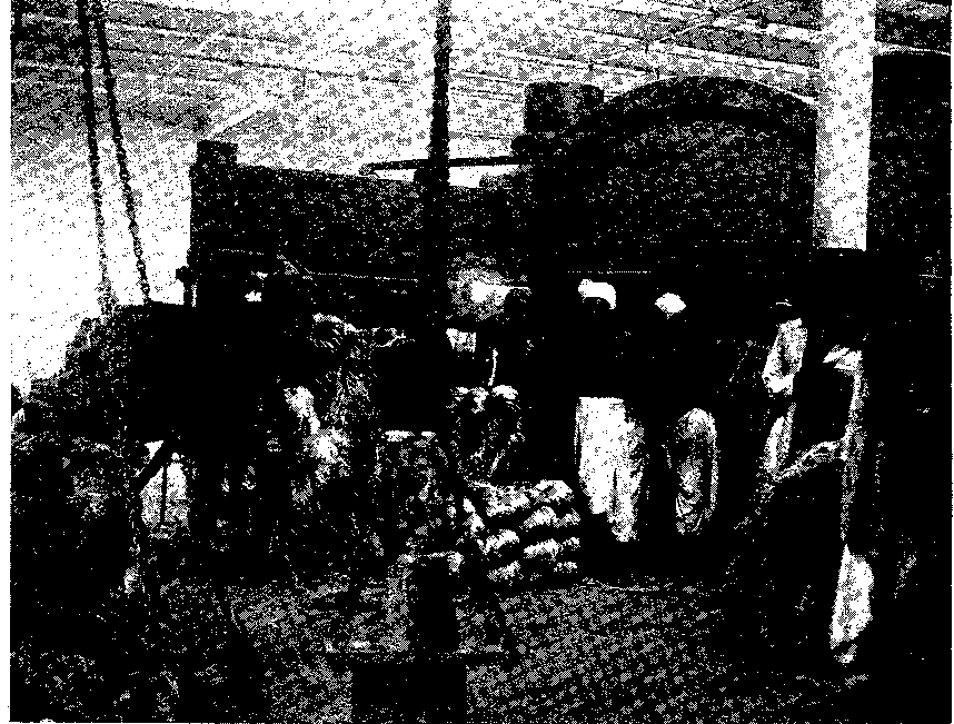
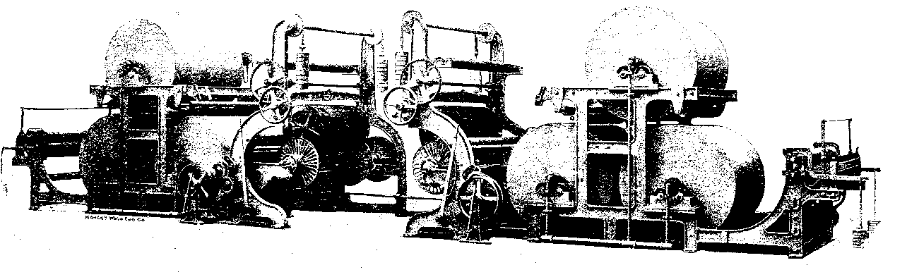
Most of the baling presses used in the press houses in the Calcutta district are made in Liverpool, and are provided with the most efficient type of pumps and mechanical parts. Fig. 5 illustrates one of these huge presses with a number of natives in close proximity. Two or three distinct operations are conducted simultaneously by different groups of operatives, and ingenious mechanism is essential for the successful prosecution of the work. Two such presses as that illustrated in Fig. 5 are capable, under efficient administration, of turning out 130 bales of 400 lbs. each in one hour. The fibre is compressed into comparatively small bulk by hydraulic pressure equal to 6,000 lbs. per square inch, and no packed bale must exceed in cubical capacity 11 cubic feet after it leaves the press; it is usual for freight purposes to reckon 5 bales or 55 cubic feet per ton. (Now changed to 50 cubic feet.)
The jute bales are loaded either at the wharf or in the river from barges into large steamers, many of which carry from 30,000 to 46,000 bales in one cargo to the European ports. One vessel brought 70,000 bales.
As already mentioned, jute is sold under guarantees as to quality, and all disputes must be settled by arbitration. Although this is the usual method of sale, it is not uncommon for quantities of jute to be shipped unsold, and such quantities may be disposed of on the "Spot." It is a common practice to sell a number of bales to sample, such number depending generally upon the extent of the quantity, or "parcel," as it is often called. The contract forms are very complete, and enable the business to be conducted to the satisfaction of all concerned in the trade.
It will be understood that, in the yearly production of such a large quantity of jute fibre from various districts, and obtained from plants which have been grown under variable climatic and agricultural conditions, in some cases the fibre will be of the finest type procurable, while in other cases it will be of a very indifferent type and unsuitable for use in the production of the ordinary classes of yarns and fabrics. On the other hand, it should be stated that there is such a wide range of goods manufactured, and additional varieties occasionally introduced, that it appears possible to utilize all the kinds of fibre in any year; indeed, it seems as if the available types of fibre each season create demands for a corresponding type of manufactured product.
The crops produced will, obviously, vary in amount and value annually, but a few figures will help the reader to estimate in some degree the extent of the industry and its development in various parts of the world.
                EXPORTS OF JUTE FROM INDIA


            Year.     Tons.       Bales.


            1828        18      300 lbs/bale
            1832       182      300 lbs/bale
            1833       300      300 lbs/bale
            1834       828      300 lbs/bale
            1835     1,222      300 lbs/bale
            1836        16      300 lbs/bale
            1837       171      300 lbs/bale
                    JUTE PRODUCTION IN INDIA


              Season.      Tons.    Bales (400 lbs.).


            1850-51.     28,247       158,183
            1860-61.     46,182       258,619
            1862-63.    108,776       609,146
            1863-64.    125,903       707,056
            1872-73.    406,335     2,275,476
            1880-81.    343,596     1,924,137
            1886-87.    413,664     2,316,518
            1892-93.    586,258     3,083,023
            1896-97.    588,141     3,293,591
            1902-03.    580,967     3,253,414
            1906-07.    829,273     4,643,929
            1907-08.  1,761,982     9,867,100
            1908-09.  1,135,856     6,360,800
            1909-10.  1,302,782     7,295,580
            1910-11   1,434,286     8,032,000
            1911-12.  1,488,339     8,334,700
            1912-13.  1,718,180     9,621,829
            1913-14.  1,580,674     8,851,775
            1914-15.  1,898,483    10,631,505
            1915-16.  1,344,417     7,528,733
            1916-17.  1,493,976     8,366,266
            1917-18.  1,607,922     9,004,364
            1918-19.  1,278,425     7,159,180
            1919-20.  1,542,178     8,636,200
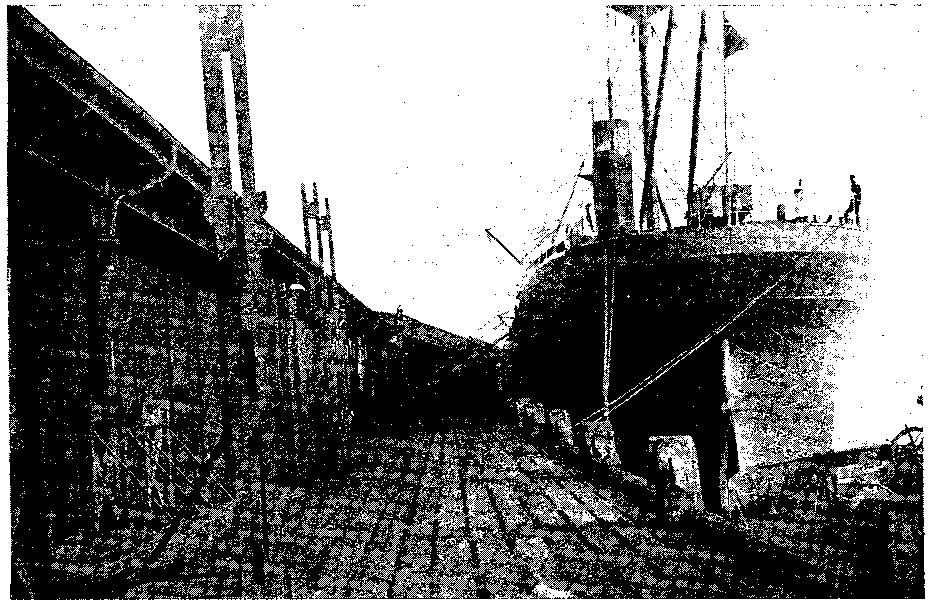
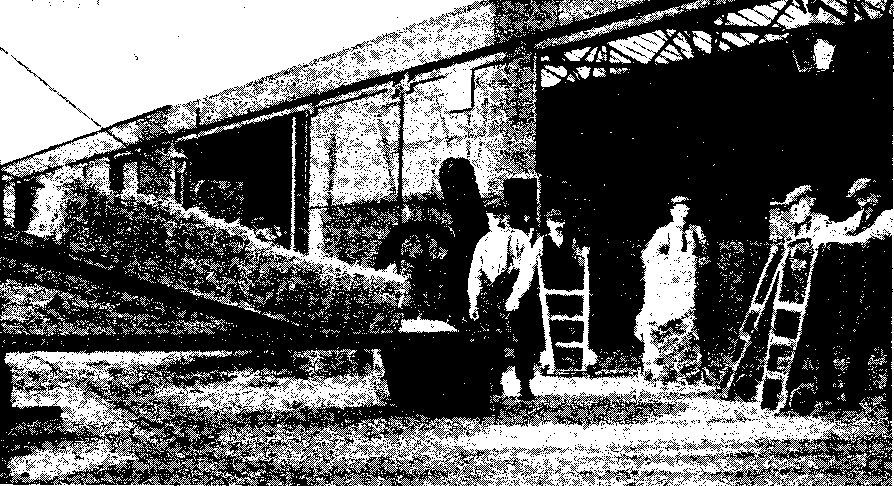
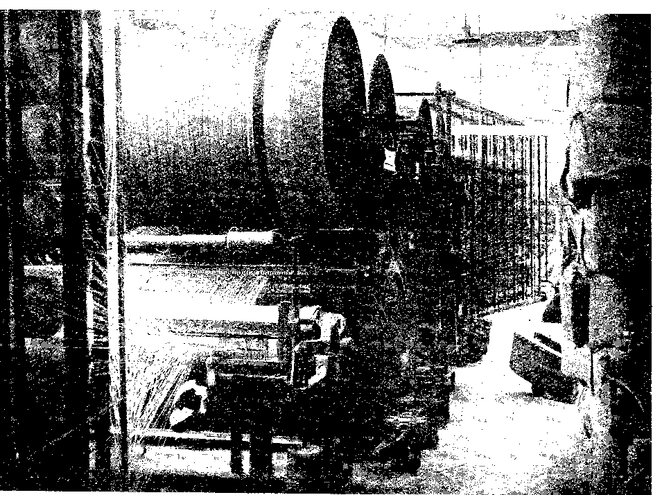
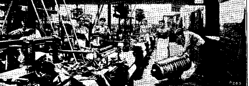
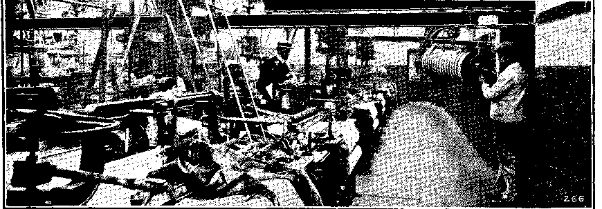
A large vessel containing bales of jute is berthed on the quay-side adjoining the jute sheds in Fig. 6. The bales are raised quickly from the hold by means of a hydraulic-engine, scarcely visible in Fig. 6 since it is at the far end of the vessel, but seen clearly in Fig. 7. When the bales are raised sufficiently high, they are guided to the comparatively steep part of a chute from which they descend to the more horizontal part as exemplified in Fig. 7. They are then removed by means of hand-carts as shown, taken into the shed, and piled or stored in some suitable arrangement with or without the aid of a crane. Motor and other lorries are then used to convey the bales to the various mills where the first actual process in what is termed spinning takes place. It will be understood that the bales are stored in the spinner's own stores after having been delivered as stated.
Bale Opening. Each spinner, as already indicated, stores his bales of jute of various "marks," i.e. qualities, in a convenient manner, and in a store or warehouse from which any required number of bales of each mark can be quickly removed to the preparing department of the mill.
In the woollen industry, the term "blending" is used to indicate the mixing of different varieties of material (as well as different kinds of fibres) for the purpose of obtaining a mixture suitable for the preparing and spinning of a definite quality and colour of material. In much the same way, the term "batching" is used in the jute industry, although it will be seen shortly that a more extensive use is made of the word. A "batch," in its simplest definition, therefore indicates a number of bales which is suitable for subsequent handling in the Batching Department. This number may include 5, 6, 7 or more bales of jute according to the amount of accommodation in the preparing department.
All the above bales of a batch may be composed of the same standard quality of jute, although the marks may be different. It must be remembered that although the marks have a distinct reference to quality and colour, they actually represent some particular firm or firms of balers or merchants. At other times, the batch of 5 to 10 bales may be composed of different qualities of jute, the number of each kind depending partly upon the finished price of the yarn, partly upon the colour, and partly upon the spinning properties of the combination.
It will be understood that the purpose for which the finished yarn is to be used will determine largely the choice of the bales for any particular batch. For example, to refer to a simple differentiation, the yarn which is to be used for the warp threads in the weaving of cloth must, in nearly every case, have properties which differ in some respects from the yarn which is to be used as weft for the same cloth.
On the whole, it will be found advantageous, when the same grade of jute is required, to select a batch from different balers' marks so that throughout the various seasons an average quality may be produced. The same class of yarn is expected at all times of the year, but it is well known that the properties of any one mark may vary from time to time owing to the slight variations in the manipulation of the fibre at the farms, and to the variations of the weather during the time of growth, and during the season generally.
A list of the bales for the batch is sent to the batching department, this list being known as a "batch-ticket." The bales are, of course, defined by their marks, and those mentioned on the batch-ticket must be rigidly adhered to for one particular class of yarn; if there is any chance of one kind running short, the condition should be notified in time so that a suitable mark may be selected to take its place without effecting any great change in the character or quality of the yarn.
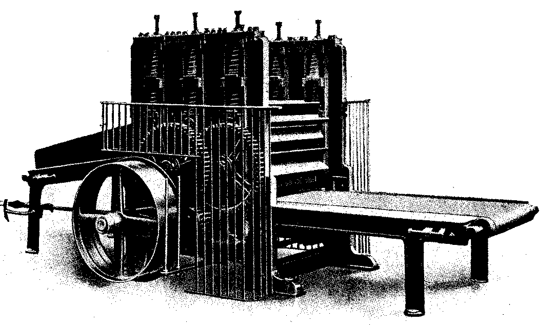
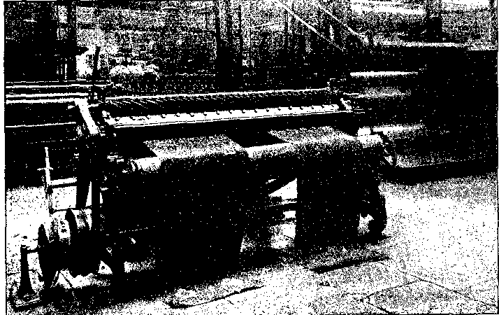
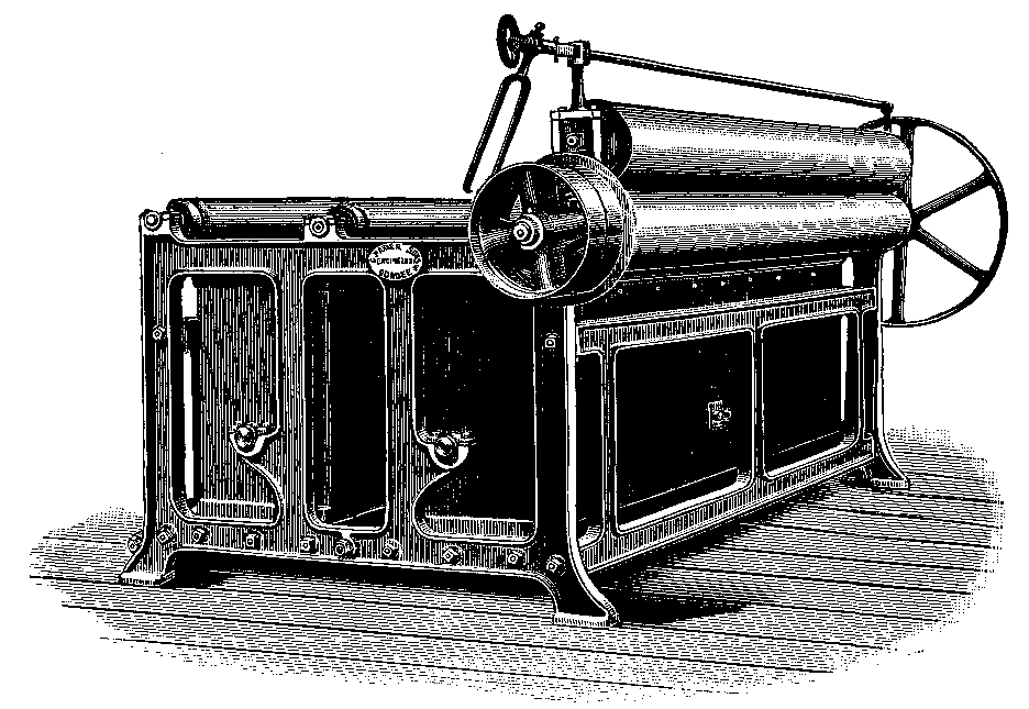
When the number and kind of bales have been selected and removed from the groups or parcels in the store or warehouse, they are conveyed to the batching department, and placed in a suitable position near the first machine in the series. It need hardly be mentioned that since the fibre, during the operation of baling, is subjected to such a high hydraulic pressure, the bale presents a very solid and hard appearance, see Fig. 7, for the various so-called "heads" of fibre have been squeezed together and forced into a very small bulk. In such a state, the heads are quite unfitted for the actual batching operation; they require to be opened out somewhat so that the fibres will be more or less separated from each other. This operation is termed "opening" and the process is conducted in what is known as a "bale opener," one type of which is illustrated in Fig. 8, and made by Messrs. Urquhart, Lindsay & Co., Ltd., Dundee.
The various bales of the batch are arranged in a suitable manner near the feed side of the machine, on the left in the view, so that they can be handled to the best advantage. The bands or ropes, see Fig. 7, are removed from the bale in order that the heads or large pieces of jute can be separated. If any irregularity in the selection of the heads from the different bales of the batch takes place in this first selection of the heads of jute, the faulty handling may affect subsequent operations in such a way that no chance of correcting the defect can occur; it should be noted at this stage that if there are slight variations of any kind in the fibres, it is advisable to make special efforts to obtain a good average mixture; as a matter of fact, it is wise to insist upon a judicious selection in every case. The usual variations are--the colour of the fibre, its strength, and the presence of certain impurities such as stick, root, bark or specks; if the pieces of jute, which are affected adversely by any of the above, are carefully mixed with the otherwise perfect fibre, most of the faults may disappear as the fibre proceeds on its way through the different machines.
The layers of heads are often beaten with a heavy sledge hammer in hand batching, but for machine batching a bale opener is used, and this operation constitutes the preliminary opening. As already indicated, the heads of jute are fed into the machine from the left in Fig. 8, each head being laid on a travelling feed cloth which carries the heads of jute successively between a pair of feed rollers from which they are delivered to two pairs of very deeply-fluted crushing rollers or breakers. The last pair of deep-fluted rollers is seen clearly on the right in the figure. These two pairs of heavy rollers crush and bend the compressed heads of jute and deliver them in a much softer condition to the delivery sheet on the right. The delivery sheet is an endless cloth which has a continuous motion, and thus the softened heads are carried to the extreme right, at which position they are taken from the sheet by the operatives. The upper rollers in the machine may rise in their bearings against the downward pressure of the volute springs on the bearings; this provision is essential because of the thick and thin places of the heads.
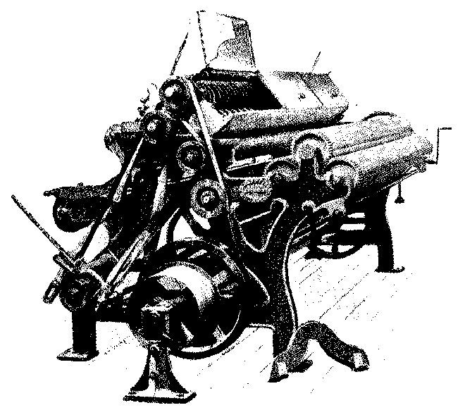
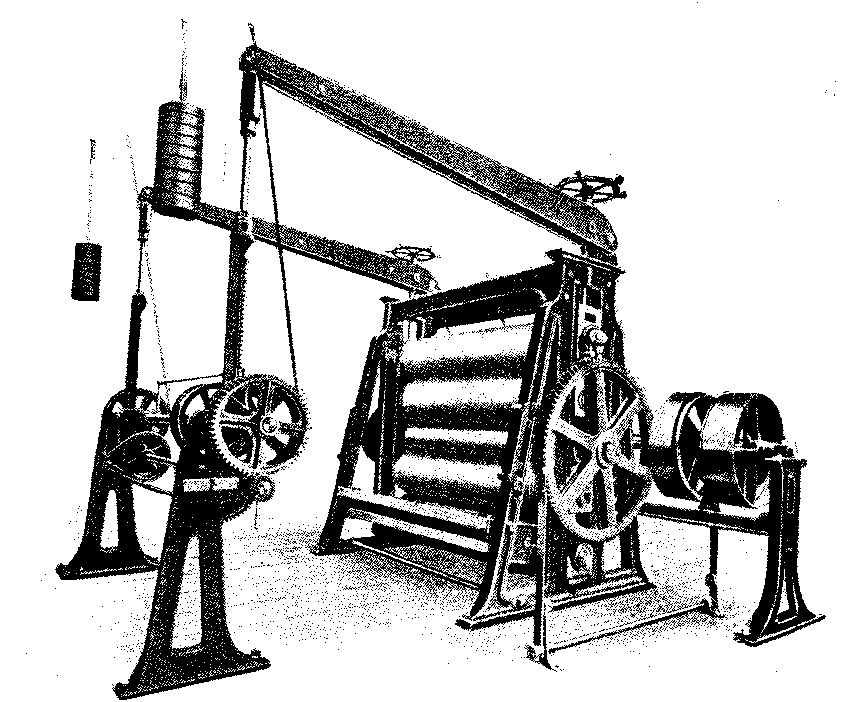
A different type of bale opener, made by Messrs. Charles Parker, Sons, & Co., Dundee, and designed from the Butchart patent is illustrated in Fig. 9. It differs mainly from the machine illustrated in Fig. 8 in the shape of the crushing or opening rollers.
It will be seen on referring to the illustration that there are three crushing rollers, one large central roller on the top and situated between two lower but smaller rollers. Each roller has a series of knobs projecting from a number of parallel rings. The knobs are so arranged that they force themselves into the hard layers of jute, and, in addition to this action, the heads of jute have to bend partially round the larger roller as they are passing between the rollers. This double action naturally aids in opening up the material, and the machine, which is both novel and effective, gives excellent results in practice. The degree of pressure provided for the top roller may be varied to suit different conditions of heads of jute by the number of weights which are shown clearly in the highest part of the machine in the form of two sets of heavy discs.
The driving side, the feed cloth, and the delivery cloth in this machine are placed similarly to the corresponding parts of the machine illustrated in Fig. 8, a machine which also gives good results in practice.
In both cases the large heads are delivered in such a condition that the operatives can split them up into pieces of a suitable size quite freely.
The men who bring in the bales from the store take up a position near the end of the delivery cloth; they remove the heads of jute as the latter approach the end of the table, and then pass them to the batchers, who split them. The most suitable size of pieces are 2-1/2 to 3 lbs. for a piece of 7 feet to 8 feet in length, but the size of the pieces is regulated somewhat by the system of feeding which is to be adopted at the breaker-card, as well as by the manager's opinion of what will give the best overall result.
After the heads of jute have been split up into suitable smaller pieces, they are placed in any convenient position for the batcher or "striker-up" to deal with. If the reader could watch the above operation of separating the heads of jute into suitable sizes, it would perhaps be much easier to understand the process of unravelling an apparently matted and crossed mass of fibre. As the loosened head emerges from the bale-opener, Figs. 8 or 9, it is placed over the operative's arm with the ends of the head hanging, and by a sort of intuition acquired by great experience, she or he grips the correct amount of fibre between the fingers, and by a dexterous movement, and a simultaneous shake of the whole piece, the handful just comes clear of the bulk and in much less time than it takes to describe the operation.
As the pieces are thus detached from the bulk, they are laid on stools or tables, or in stalls or carts, according to the method by means of which the necessary amount of oil and water is to be added for the essential process of lubrication; this lubrication enables the fibre to work freely in the various machines.
Softening and Softening Machines. Two distinct courses are followed in the preparation of the jute fibre after it leaves the bale opener, and before it is carded by the breaker card. These courses are designated as--
1. Hand Batching.
2. Machine Batching.
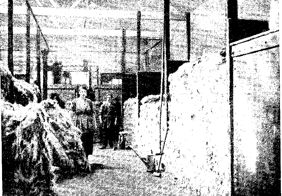
In the former process, which is not largely practised, the pieces of jute are neatly doubled, while imparting a slight twist, to facilitate subsequent handling, and laid in layers in large carts which can be wheeled from place to place; if this method is not convenient, the pieces are doubled similarly and deposited in large stalls such as those illustrated in Fig. 10.
On the completion of each layer, or sometimes two layers, the necessary measured amount of oil is evenly sprayed by hand over the pieces from cans provided with suitable perforated outlets--usually long tubes. After the oil has been added, water, from a similar sprayer attached by tubing to a water tap, is added until the attendant has applied what he or she considers is the proper quantity. The ratio between a measured amount of oil and an unmeasured amount of water is thus somewhat varied, and for this reason the above method is not to be commended. A conscientious worker can, however, with judgment, introduce satisfactory proportions which are, of course, supplied by the person in charge. In Fig. 10, the tank on the right is where the oil is stored, while the oil can, and the spray-pipe and tube for water, are shown near the second post or partition on the right.
The first stall--that next to the oil tank--in Fig. 10 is filled with the prepared pieces, and the contents are allowed to remain there for some time, say 24 hours, in order that the material may be more or less uniformly lubricated or conditioned. At the end of this time, the pieces are ready to be conveyed to and fed into the softening machines where the fibres undergo a further process of bending and crushing.
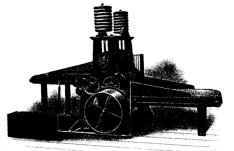
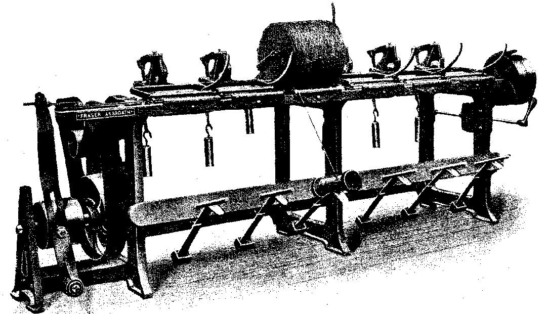
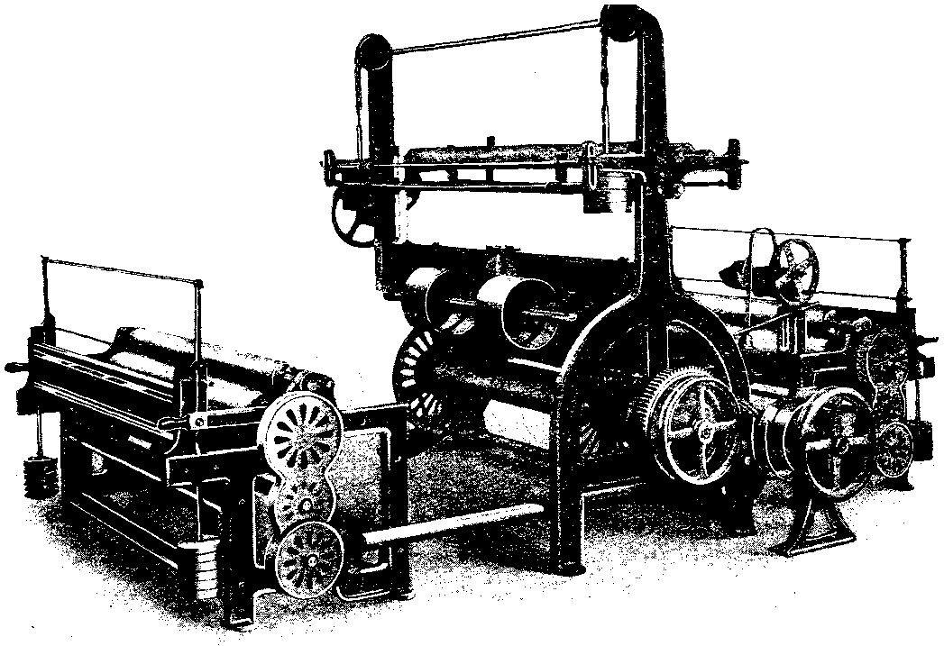
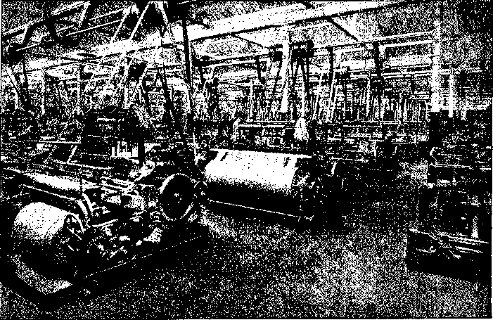
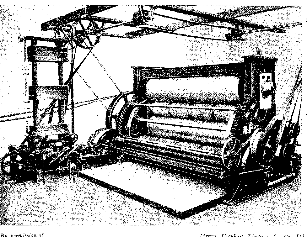
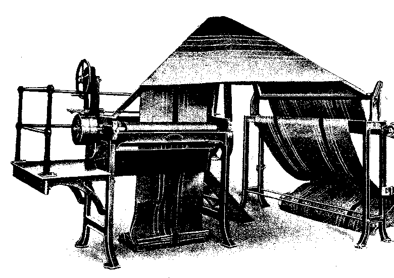
All softening machines for jute, or softeners as they are often called, are similar in construction, but the number of pairs of rollers varies according to circumstances and to the opinions of managers. Thus, the softener illustrated in Fig. 11, which, in the form shown, is intended to treat jute from the above-mentioned stalls, is made with 47, 55, 63 or 71 pairs of rollers or any other number which, minus 1, is a measure of 8. The sections are made in 8's. The illustration shows only 31 pairs.
The first pair of rollers--that next to the feed sheet in the foreground of Fig. 11--is provided with straight flutes as clearly shown. All the other rollers, however, are provided with oblique flutes, such flutes making a small angle with the horizontal. What is often considered as a standard softening machine contains 63 pairs of fluted rollers besides the usual feed and delivery rollers. As mentioned above, this number is varied according to circumstances.
The lubricated pieces of jute are fed on to the feed roller sheet, and hence undergo a considerable amount of bending in different ways before they emerge from the delivery rollers at the other end of the machine.
Machine batching is preferred by many firms because the application of oil and water, and the proportion of each, are much more uniform than they are by the above mentioned process of hand batching. On the other hand, there is no time for conditioning the fibre because the lubrication and the softening are proceeding simultaneously, although conditioning may proceed while the fibre remains in the cart after it has left the softener.
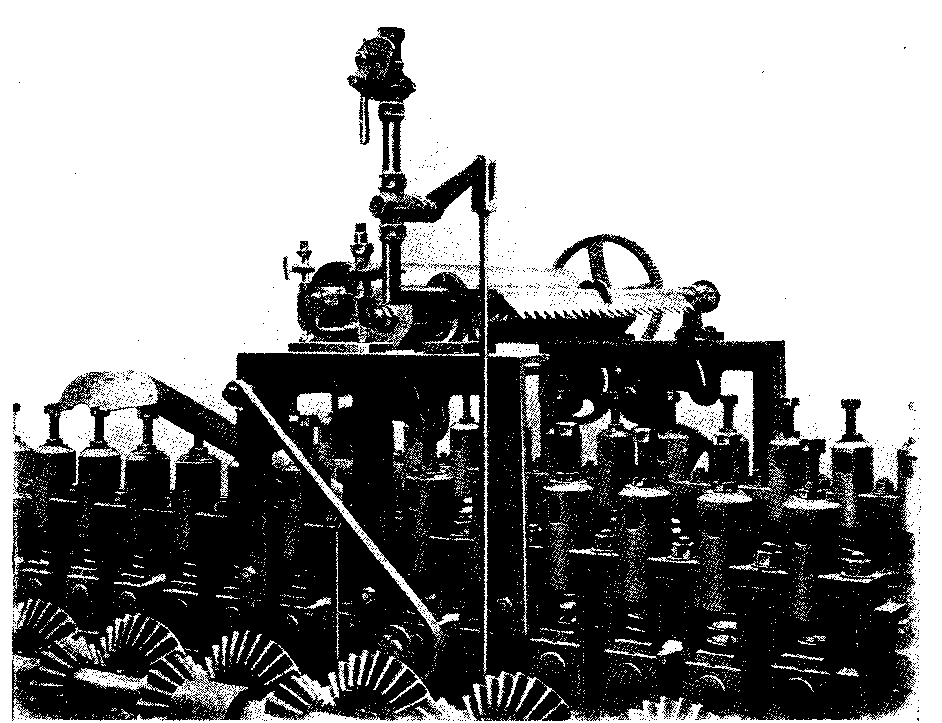
The mechanical apparatus as made by Messrs. Urquhart, Lindsay & Co., Ltd., Dundee, for depositing the oil and water on the pieces or "stricks" of jute is illustrated in Fig. 12. The actual lubricating equipment is situated on the top of the rectangular frame in the centre of the illustration. This frame is bolted to the side frames of the softening machine proper, say that shown in Fig. 11. Its exact position, with respect to its distance from the feed, is a matter of choice, but the liquid is often arranged to fall on to the material at any point between the second and twelfth rollers.
In Fig. 12 the ends of 13 rollers of the upper set are seen clearly, and these upper rollers are kept hard in contact with the stricks or pieces of jute by means of the powerful springs shown immediately above the roller bearings and partially enclosed in bell-jars.
Outside the rectangular frame in Fig. 12 are two rods, one vertical and the other inclined. The straight or vertical rod is attached by suitable levers and rods to the set-on handles at each end of the machine and to the valve of the water pipe near the top of the frame, while the upper end of the inclined or oblique rod is fulcrumed on a rod projecting from the frame. The lower or curved end of the oblique rod rests against the boss of one of the upper rollers.
The water valve is opened and closed with the starting and stopping of the machine, but the oblique rod is moved only when irregular feeding takes place. Thus, the upper rollers rise slightly against the pressure of the springs when thick stricks appear; hence, when a thick place passes under the roller which is in contact with the curved end of the oblique rod, the end moves slightly clockwise, and thus rotates the fulcrum rod; this results in an increased quantity of oil being liberated from the source of supply, and the mechanism is so arranged that the oil reaches the thick part of the strick. When the above-mentioned upper roller descends, due to a decrease in the thickness of the strick, the oblique rod and its fulcrum is moved slightly counter-clockwise, and less oil is liberated for the thin part of the strick. It will be understood that all makers of softening machines supply the automatic lubricating or batching apparatus when desired.
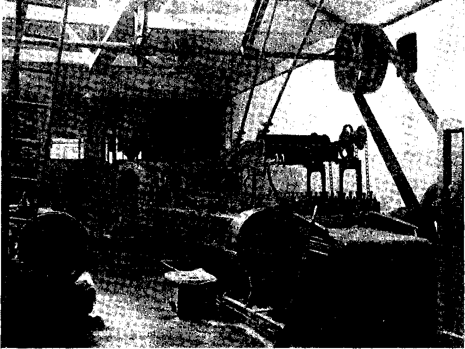
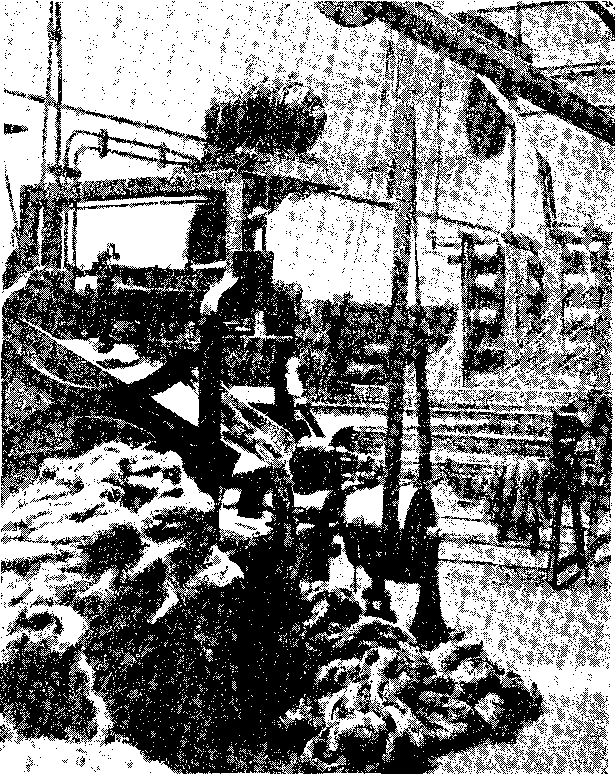
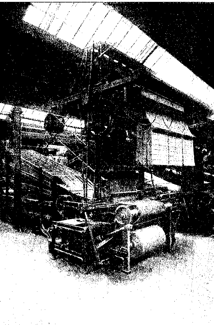
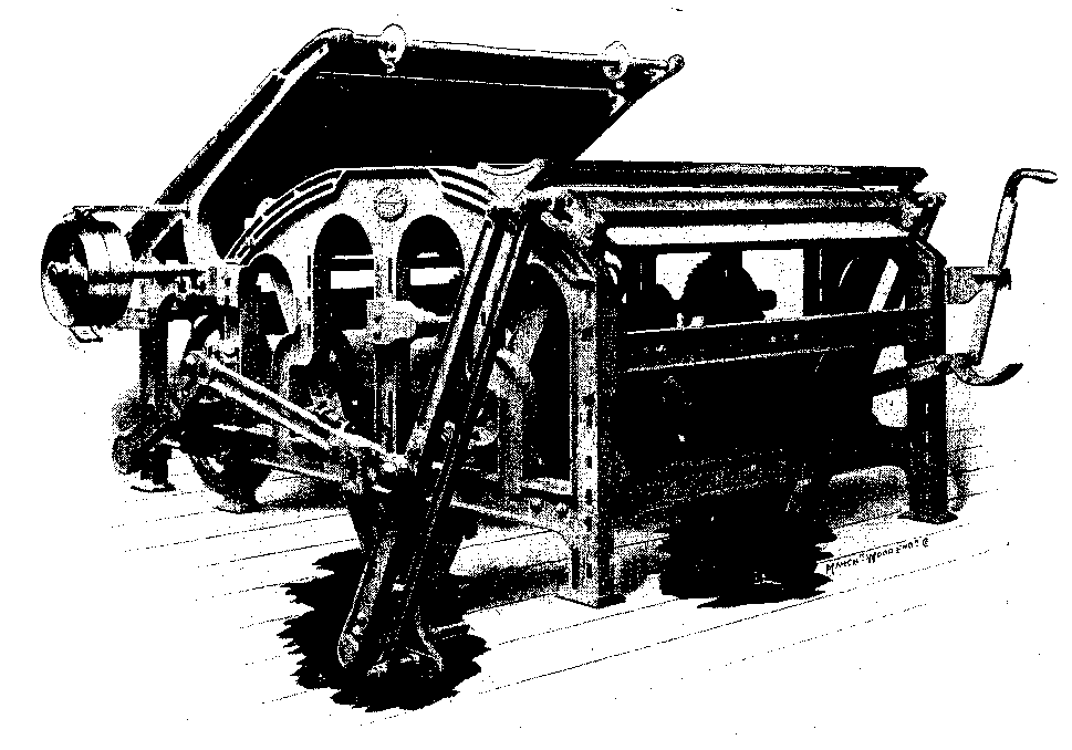
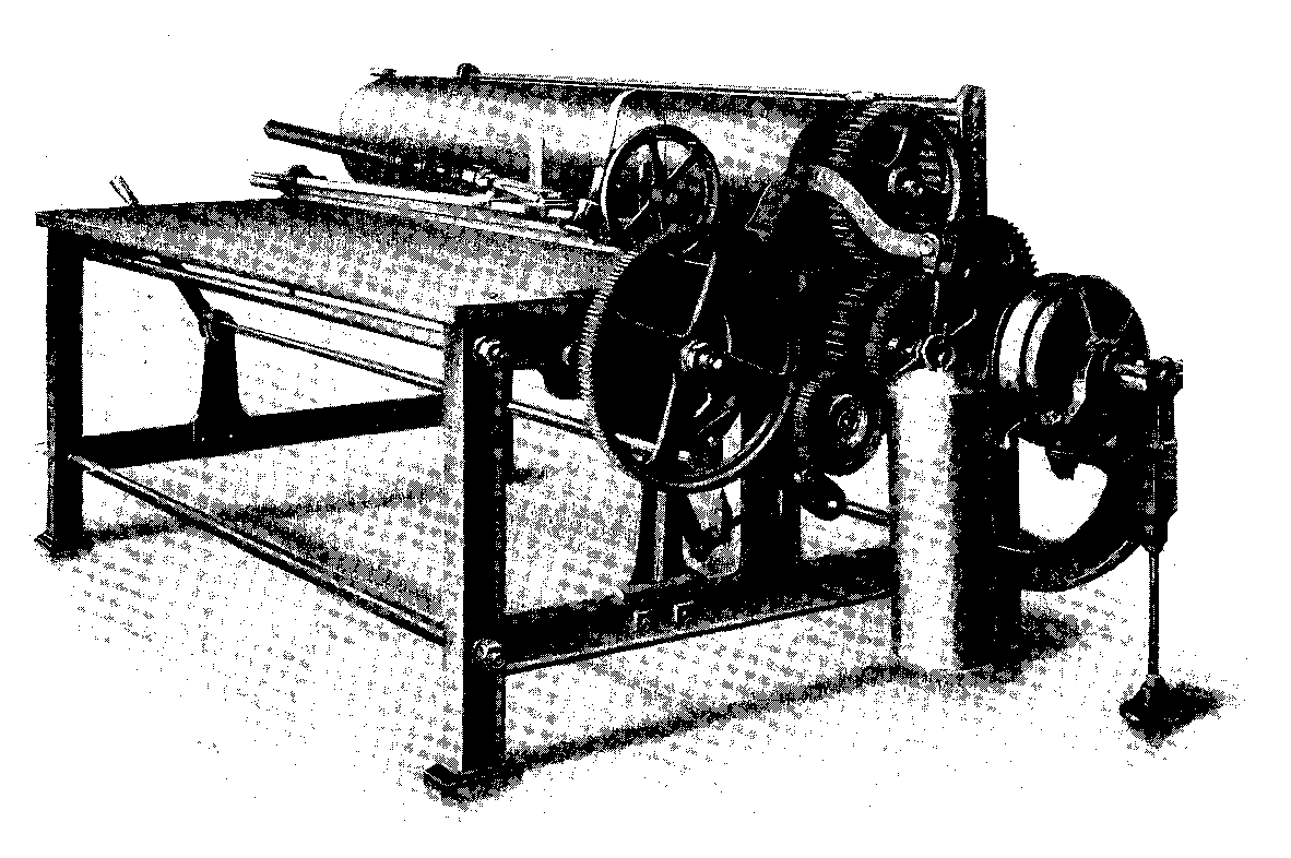
A view of a softener at work appears in Fig. 13. The bevel wheels at the end of the rollers are naturally covered as a protection against accidents. In many machines safety appliances are fitted at the feed end so that the machine may be automatically stopped if the operative is in danger. The batching apparatus for this machine is of a different kind from that illustrated in Fig. 12; moreover, it is placed nearer the feed rollers than the twelfth pair. The feed pipes for the oil and the water are shown coming from a high plane, and the supply is under the influence of chain gearing as shown on the right near the large driving belt from the drum on the shafting.
The feed roller in this machine is a spirally fluted one, and the nature of the flutes is clearly emphasized in the view. The barrow of jute at the far end of the machine is built up from stricks which have passed through the machine, and these stricks are now ready for conditioning, and will be stored in a convenient position for future treatment.
While the jute as assorted and baled for export from India is graded in such a way that it may be used for certain classes of yarn without any further selection or treatment, it may be possible to utilize the material to better advantage by a judicious selection and treatment after it has undergone the operation of batching.
What are known as cuttings are often treated by a special machine known as a "root-opener." The jute cuttings are fed into the machines and the fibre rubbed between fixed and rotating pins in order to loosen the matted ends of stricks. Foreign matter drops through the openings of a grid to the floor, and the fibre is delivered on to a table, or, if desired, on to the feed sheet of the softener.
The root ends of stricks are sometimes treated by a special machine termed a root-comber with the object of loosening the comparatively hard end of the strick. A snipping machine or a teazer may also be used for somewhat similar purposes, and for opening out ropes and similar close textures.
The cuttings may be partially loosened by means of blows from a heavy iron bar; boiling water is then poured on the fibre, and then the material is built up with room left for expansion, and allowed to remain in this condition for a few days. A certain quantity of this material may then be used along with other marks of jute to form a batch suitable for the intended yarn.
A very common practice is to cut the hard root ends off by means of a large stationary knife. At other times, the thin ends of the stricks are also cut off by the same instrument. These two parts are severed when it is desired to utilize only the best part of the strick. The root ends are usually darker in colour than the remainder, and hence the above process is one of selection with the object of securing a yarn which will be uniform in colour and in strength.
Breaker and Finisher Cards. After the fibre from the softening machine has been conditioned for the desired time, it is ready for one of the most important processes in the cycle of jute manufacture; this process is termed carding, and is conducted in two distinct types of machines--
The functions of the two machines are almost identical; indeed, one might say that the work of carding should be looked upon as one continuous operation.
The main difference between the two types of machines is in the method of feeding, and the degree of fineness or setting of the small tools or pins which perform the work. In both cases the action on the stricks of jute is equivalent to a combined combing and splitting movement, and the pins in the various rollers move relatively to each other so that while the pins of a slowly-moving roller allow the strick or stricks (because there are several side by side) to pass slowly and gradually from end to end, the pins of another but quickly-moving roller perform the splitting and the combing of the fibre. The pins of the slowly-moving roller hold, so to speak, the strick, while the pins of the quickly-moving roller comb out the fibres and split adhering parts asunder so as to make a comparatively fine division.
The conditioned stricks from the softening machine are first arranged in some suitable receptacle and within easy reach of the operative at the back or feed side of the breaker card. A receptacle, very similar to that used at the breaker card, appears near the far end of the softening machine in Fig. 13.
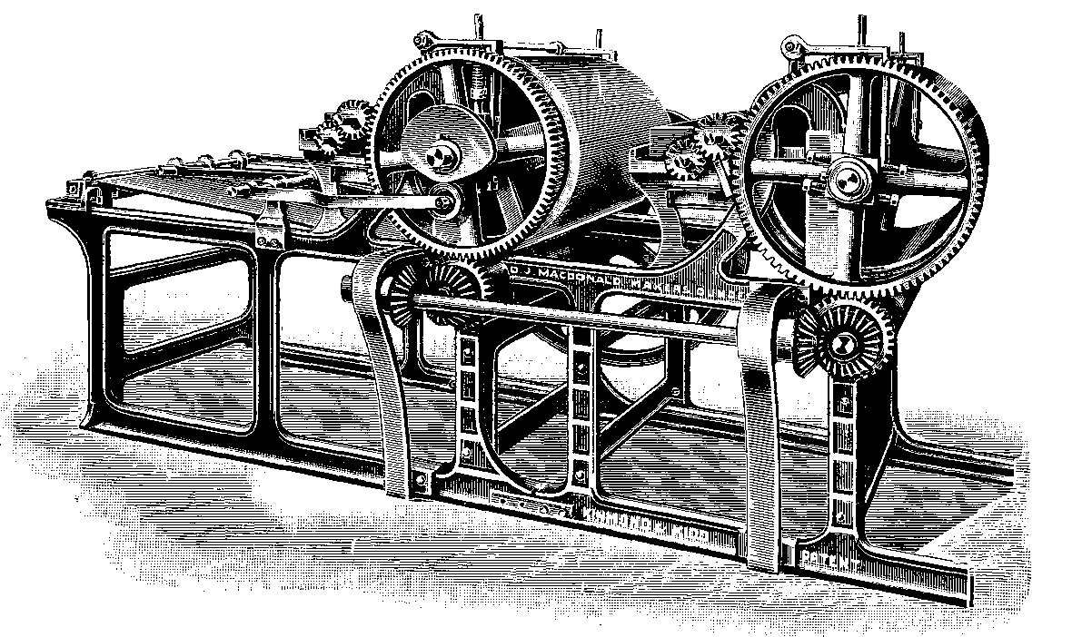
A modern breaker card is illustrated in Fig. 14. The feed or back of the card is on the extreme right, the delivery or front of the card on the extreme left, while the gear side of the card is facing the observer. The protecting cages were removed so that the wheels would be seen as clearly as possible.
Some of the stricks of fibre are seen distinctly on the feed side of the figure; they are accommodated, as mentioned, in a channel-shaped stand on the far side of the inclined feed sheet, or feed cloth, which leads up to and conveys the stricks into the grip of the feeding apparatus. This particular type is termed a "shell" feed because the upper contour of the guiding feed bracket is shaped somewhat like a shell. There is a gradually decreasing and suitably-sized gap between the upper part of the shell and the pins of the feed roller.
The root ends of the pins in this roller lead, and the stricks of fibre are gripped between the pins and the shell, and simultaneously carried into the machine where they come into contact with the points of the pins in the rapidly-revolving large roller, termed a cylinder. The above-mentioned combing and splitting action takes place at this point as well as for a distance of, say, 24 inches to 30 inches below. The fibres which are separated at this stage are carried a little further round until they come into contact with the points of the pins in the above-mentioned slowly-moving roller, termed a "worker," and while the fibres are moving slowly forward under the restraining influence of the worker, they are further combed and split. A portion of the fibres is carried round by the pins of the worker from which such fibres are removed by the quicker moving pins of the second roller of the pair, termed a "stripper," and in turn these fibres are removed from the pins of the stripper by the much quicker moving pins of the cylinder.
The above operations conducted by the first pair of rollers (worker and stripper) in conjunction with the cylinder, are repeated by a second and similar pair of rollers (worker and stripper), and ultimately the thin sheet of combed and split fibres comes into contact with the pins of the doffer from which it is removed by the drawing and pressing rollers. The sheet of fibres finally emerges from these rollers into the broad and upper part of the conductor. This conductor, made mostly of tin and V-shaped, is shown clearly on the left of the machine in Fig. 14. Immediately the thin film or sheet of fibres enters the conductor, it is caused as a body gradually to contract in width and, of course, to increase in thickness, and is simultaneously guided and delivered to the delivery rollers, and from these to the sliver can, distinctly seen immediately below the delivery rollers. The sliver is seen emerging from the above rollers and entering the sliver can.
The fibres in this machine are thus combed, split and drawn forward relatively to each other, in addition to being arranged more or less parallel to each other. The technical term "draft" is used to indicate the operation of causing the fibres to slip on each other, and in future we shall speak about this attenuation or drawing out of the fibres by this special term "draft."
It will be evident that, since the sliver is delivered into the can at the rate of about 50 yards per minute, this constant flow will soon provide a sufficient length of sliver to fill a sliver can, although the latter may hold approximately 20 lbs. The machine must, of course, deliver its quota to enable succeeding machines to be kept in practically constant work. As a matter of fact, the machines are arranged in what are termed "systems," so that this desirable condition of a constant and sufficient feed to all may be satisfactorily fulfilled.
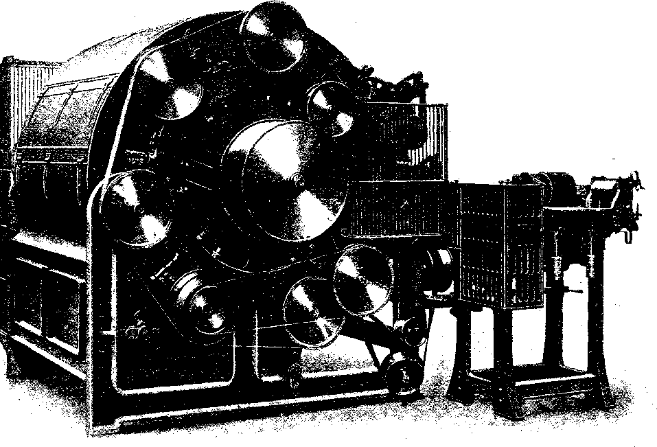
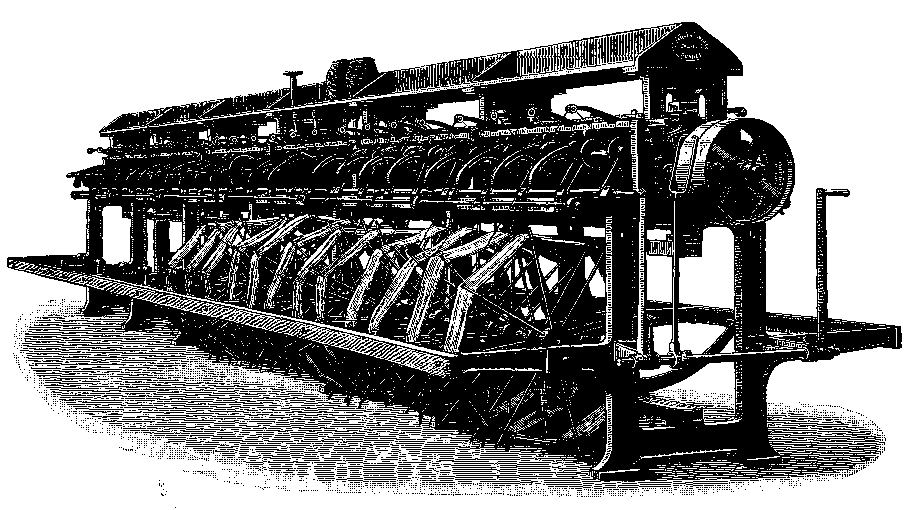
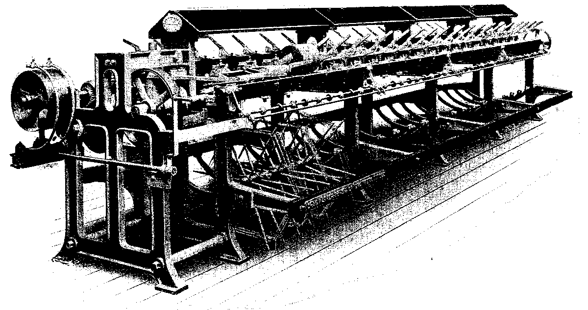
The driving or pulley side of the breaker card is very similar to that shown in Fig. 15 which, however, actually represents the pulley side of one type of finisher card as made by Messrs. Douglas Fraser & Sons, Ltd., Arbroath. All finisher cards are fed by slivers which have been made as explained in connection with the breaker card, but there are two distinct methods of feeding the slivers, or rather of arranging the slivers at the feed side. In both cases, however, the full width of the card is fed by slivers laid side by side, with, however, a thin guide plate between each pair, and one at each extreme end.
One very common method of feeding is to place 10 or 12 full sliver cans--which have been prepared at the breaker card--on the floor and to the right of the machine illustrated in Fig. 15. The sliver from each can is then placed into the corresponding sliver guide, and thus the full width of the machine is occupied. The slivers are guided by the sliver guides on to an endless cloth or "feed sheet" which, in turn, conveys them continuously between the feed rollers. The feed apparatus in such machines is invariably of the roller type, and sometimes it involves what is known as a "porcupine" roller. It will be understood that the feeding of level slivers is a different problem from that which necessitates the feeding of comparatively uneven stricks.
The slivers travel horizontally with the feed-sheet and enter the machine at a height of about 4 feet from the floor. They thus form, as it were, a sheet of fibrous material at the entrance, and this sheet of fibres comes in contact with the pins of the various pairs of rollers, the cylinder, and the doffer, in much the same way as already described in connection with the breaker card. There are, however, more pairs of rollers in the finisher card than there are in the breaker card, for while the latter is provided with two pairs of rollers, the former may be arranged with 3, 4, 5 or even 6 pairs of rollers (6 workers and 6 strippers). The number of pairs of rollers depends upon the degree of work required, and upon the opinions of the various managers.
There are two distinct types of finisher cards, viz--
The machine illustrated in Fig. 15 is of the latter type, and such machines are so-called because the various pairs of rollers are so disposed around the cylinder that they occupy almost a complete circle, and the fibre under treatment must move from pair to pair to undergo the combing and splitting action before coming into contact with the doffer. There are five pairs of rollers in the machine in Fig. 15, and all the rollers are securely boxed in, and the wheels fenced. The arrangement of the wheels on the gear side is very similar to that shown in connection with the breaker card in Fig. 14, and therefore requires no further mention. Outside the boxing comes the covers, shown clearly at the back of the machine in Fig. 15, and adapted to be easily and quickly opened when it is desired to examine the rollers and other parts.
The slivers, after having passed amongst the pins of the various rollers, and been subjected to the required degree of draft, are ultimately doffed as a thin film of fibres from the pins of the cylinder and pass between the drawing rollers to the conductor. The conductor of a finisher card is made in two widths, so that half the width of the film enters one section and the other half enters the other section. These two parallel sheets, split from one common sheet, traverse the two conductors and are ultimately delivered as two slivers about 6 inches above the point or plane in which the 10 or 12 slivers entered, and on to what is termed a "sliver plate." The two slivers are then guided by horns projecting from the upper surface of the sliver plate, made to travel at right angles to the direction of delivery from the mouths of the conductors, and then united to pass as a single sliver between a pair of delivery rollers on the left of the feed and delivery side and finally into a sliver can.
In special types of finishing cards, an extra piece of mechanism--termed a draw-head--is employed. The machine illustrated in Fig. 15 is provided with this extra mechanism which is supported by the small supplementary frame on the extreme right. This special mechanism is termed a "Patent Push Bar Drawing Head," and the function which it performs will be described shortly; in the meantime it is sufficient to say that it is used only when the slivers from the finisher card require extra or special treatment. A very desirable condition in connection with the combination of a finisher card and a draw-head is that the two distinct parts should work in unison. In the machine under consideration, the feed and delivery rollers of the card stop simultaneously with the stoppage of the draw-head mechanism.
One of the chief aims in spinning is that of producing a uniform thread; uniform not only in section, but in all other respects. A so-called level thread refers, in general, to a uniform diameter, but there are other equally, if not more, important phases connected with the full sense of the word uniform.
It has already been stated that in the batching department various qualities of jute are mixed as judiciously as possible in order to obtain a satisfactory mixture. Fibres of different grades and marks vary in strength, colour, cleanness, diameter, length and suppleness; it is of the utmost importance that these fibres of diverse qualities should be distributed as early as possible in the process so as to facilitate the subsequent operations.
However skilfully the work of mixing the stricks is performed in the batching department, the degree of uniformity leaves something to be desired; further improvement is still desirable and indeed necessary. It need hardly be said, however, that the extent of the improvement, and the general final result, are influenced greatly by the care which is exercised in the preliminary processes.
The very fact of uniting 10 or 12 slivers at the feed of the finisher card mixes 10 or 12 distinct lengths into another new length, and, in addition, separates in some measure the fibres of each individual sliver. It must not be taken for granted that the new length of sliver is identical with each of the individual lengths and ten or twelve times as bulky. A process of drafting takes place in the finisher card, so that the fibres which compose the combined 10 or 12 slivers shall be drawn out to a draft of 8 to 16 or even more; this means that for every yard of the group of slivers which passes into the machine there is drawn out a length of 8 to 16 yards or whatever the draft happens to be. The resulting sliver will therefore be approximately two-thirds the bulk of each of the original individual slivers. The actual ratio between them will obviously depend upon the actual draft which is imparted to the material by the relative velocities of the feed and delivery rollers.
It is only natural to expect that a certain amount of the fibrous material will escape from the rollers; this forms what is known as card waste. And in all subsequent machines there is produced, in spite of all care, a percentage of the amount fed into the machine which is not delivered as perfect material. All this waste from various sources, e.g. thread waste, rove waste, card waste, ropes, dust-shaker waste, etc., is ultimately utilized to produce sliver for heavy sacking weft.
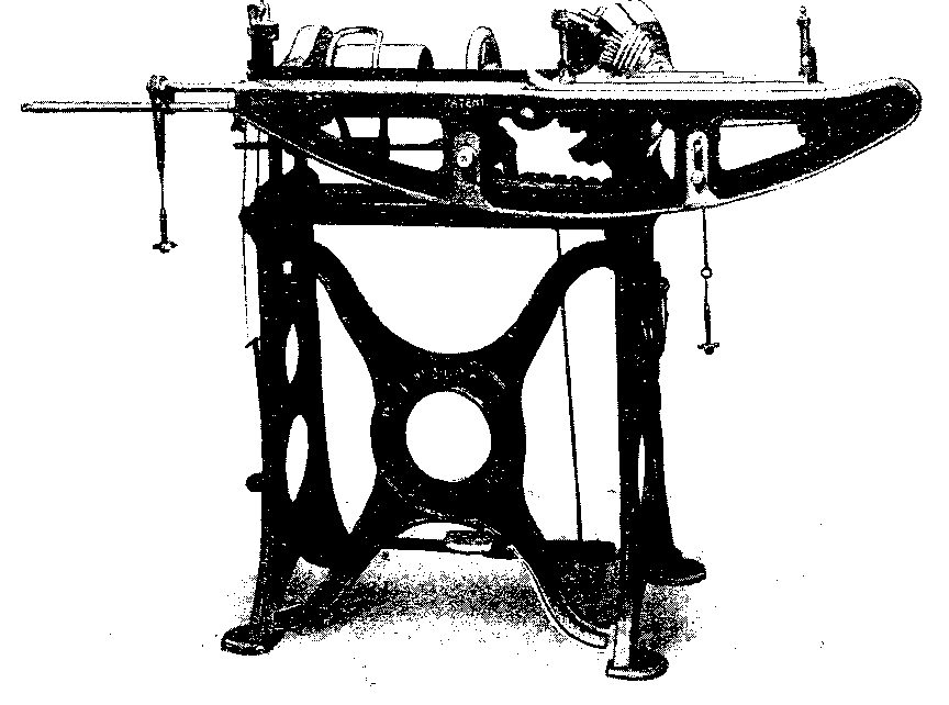
The dust-shaker, as its name implies, separates the dust from the valuable fibrous material, and finally all the waste products are passed through a waste teazer such as that made by Messrs. J. F. Low & Co., Ltd., Monifieth, and illustrated in Fig. 16. The resulting mass is then re-carded, perhaps along with other more valuable material, and made into a sliver which is used, as stated above, in the production of a cheap and comparatively thick weft such as that used for sacking.
The operations of combing and splitting as performed in both the breaker and finisher card are obviously due to the circular movement of the pins since all these (with the single exception of those in the draw-head mechanism of certain finisher cards) are carried on the peripheries of rotating rollers. In the draw-head mechanism, the pins move, while in contact with the fibres, in a rectilinear or straight path. In the machines which fall to be discussed in this chapter, viz., the "drawing frames," the action of the pins on the slivers from the finisher card is also in a straight path; as a matter of fact, the draw-head of a finisher card is really a small drawing frame, as its name implies. Moreover, each row or rather double row, of pins is carried separately by what is termed a "faller." The faller as a whole consists of three parts:
1. A long iron or steel rod with provision for being
moved in a closed circuit.
2. Pour or six brass plates, termed "gills" or
"stocks," fixed to the rod.
3. A series of short pins (one row sometimes about
1/8 in. shorter than the second row), termed gill or
hackle pins, and set perpendicularly in the above
gills.
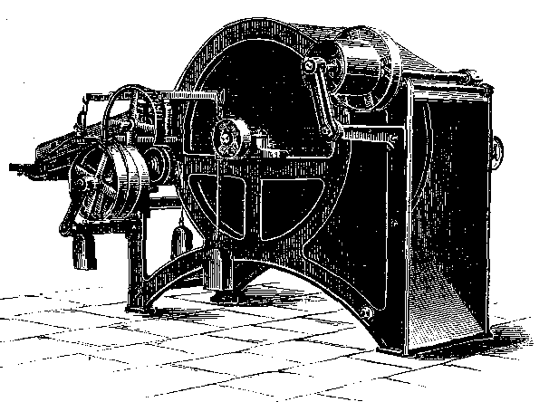
The numbers of fallers used is determined partly by the particular method of operating the fallers, but mostly by the length of the fibre. The gill pins in the fallers are used to restrain the movements of the fibres between two important pairs of rollers. There are actually about four sets of rollers from front to back of a drawing frame; one set of three rollers constitute the "retaining" rollers; then comes the drawing roller and its large pressing roller; immediately after this pair is the "slicking" rollers, and the last pair is the delivery rollers. The delivery rollers of one type of drawing frame, called the "push-bar" drawing frame, and made by Messsrs. Douglas Fraser & Sons, Ltd., Arbroath, are seen distinctly in Fig. 17, and the can or cans into which the slivers are ultimately delivered are placed immediately below one or more sections of these rollers and in the foreground of the illustration. The large pressing rollers, which are in contact with the drawing roller, occupy the highest position in the machine and near the centre of same. Between these rollers and the retaining rollers are situated the above-mentioned fallers with their complements of gill pins, forming, so to speak, a field of pins.
Each sliver, and there maybe from four to eight or more in a set, is led from its sliver can at the far side of the machine to the sliver guide and between the retaining rollers. Immediately the slivers leave the retaining rollers they are penetrated by the gill pins of a faller which is rising from the lower part of its circuit to the upper and active position. Each short length of slivers is penetrated by the pins of a rising faller, these coming up successively as the preceding one moves along at approximately the same surface speed as that of the retaining rollers. The sheet of pins and their fallers are thus continuously moving towards the drawing rollers and supporting the slivers at the same time. As each faller in succession approaches close to the drawing rollers, it is made to descend so that the pins may leave the fibres, and from this point the faller moves backwards towards the retaining roller until it reaches the other end ready to rise again in contact with the fibres and to repeat the cycle as just described. It will thus be seen that the upper set of fallers occupy the full stretch between the retaining rollers and the drawing rollers, but there is always one faller leaving the upper set at the front and another joining the set at the back.
The actual distance between the retaining rollers and the drawing rollers is determined by the length of the fibre, and must in all cases be a little greater than the longest fibre. This condition is necessary because the surface speed of the drawing roller is much greater than that of the retaining rollers; indeed, the difference between the surface speeds of the two pairs of rollers is the actual draft.
Between the retaining and drawing rollers the slivers are embedded in the gill pins of the fallers, and these move forward, as mentioned, to support the stretch of slivers and to carry the latter to the nip of the drawing rollers. Immediately the forward ends of the fibres are nipped between the quickly-moving drawing rollers, the fibres affected slide on those which have not yet reached the drawing rollers, and, incidentally, help to parallelize the fibres. It will be clear that if any fibre happened to be in the grip of the two pairs of rollers having different surface speeds, such fibre would be snapped. It is to avoid this rupture of fibres that the distance between the two sets of rollers is greater than the longest fibres under treatment. The technical word for this distance is "reach."
On emerging from the drawing rollers, the combed slivers pass between slicking rollers, and then approach the sliver plate which bridges the gap between the slicking rollers and the delivery rollers, and by means of which plate two or more individual slivers are diverted at right angles, first to join each other, and then again diverted at right angles to join another sliver which passes straight from the drawing rollers and over the sliver plate to the guide of the delivery rollers. It will thus be seen that a number of slivers, each having been drawn out according to the degree of draft, are ultimately joined to pass through a common sliver guide or conductor to the nip of the delivery rollers, and thence into a sliver can.
The push-bar drawing illustrated in Fig. 17, or some other of the same type, is often used as the first drawing frame in a set. With the exception of the driving pulleys, all the gear wheels are at the far end of the frame, and totally enclosed in dust-proof casing. The set-on handles, for moving the belt from the loose pulley to the fast pulley, or vice versa, are conveniently situated, as shown, and in a place which is calculated to offer the least obstruction to the operative. The machines are made with what are known as "two heads" or "three heads." It will be seen from the large pressing rollers that there are two pairs; hence the machine is a "two-head" drawing frame.
The slivers from the first drawing frame are now subjected to a further process of doubling and drafting in a very similar machine termed the second drawing frame. The pins in the gills for this frame are rather finer and more closely set than those in the first drawing frame, but otherwise the active parts of the machines, and the operations conducted therein, are practically identical, and therefore need no further description. It should be mentioned, however, that there are different types of drawing frames, and their designation is invariably due to the particular manner in which the fallers are operated while traversing the closed circuit. The names of other drawing frames appear below.
For the preparation of slivers for some classes of yarn it is considered desirable to extend the drawing and doubling operation in a third drawing frame; as a rule, however, two frames are considered sufficient for most classes of ordinary yarn.
The process of doubling ends with the last drawing frame, but there still remains a process by means of which the drafting of the slivers and the parallelization of the fibres are continued. And, in addition to these important functions, two other equally important operations are conducted simultaneously, viz., that of imparting to the drawn out sliver a slight twist to form what is known as a "rove" or roving, and that of winding the rove on to a large rove bobbin ready for the actual spinning frame.
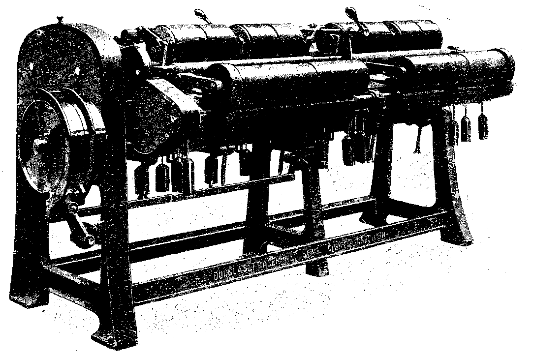
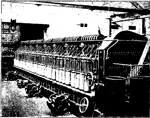
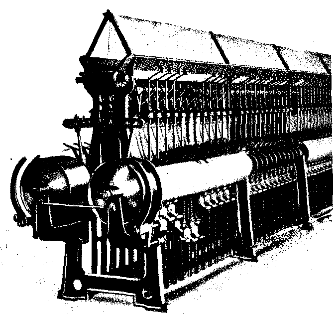
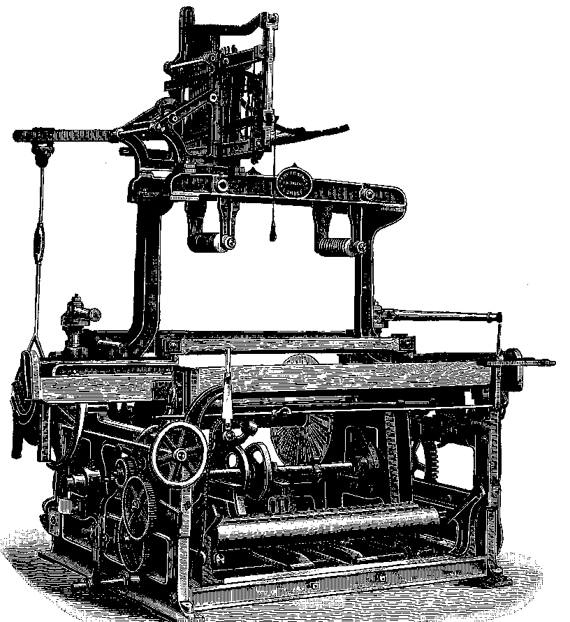
The machine in which this multiple process is performed is termed a "roving frame." Such machines are made in various sizes, and with different types of faller mechanism, but each machine is provided for the manipulation of two rows of bobbins, and, of course, with two rows of spindles and flyers. These two rows of spindles, flyers, and rove bobbin supports are shown clearly in Fig. 18, which represents a spiral roving frame made by Messrs. Douglas Fraser & Sons, Ltd., Arbroath.
Each circular bobbin support is provided with pins rising from the upper face of the disc, and these pins serve to enter holes in the flange of the bobbin and thus to drive the bobbin. The discs or bobbin supports are situated in holes in the "lifter rail" or "builder rail" or simply the "builder"; the vertical spindles pass through the centre of the discs, each spindle being provided with a "flyer," and finally a number of plates rest upon the tops of the spindles.
A roving machine at work is shown in Fig. 19, and it will be seen that the twisted sliver or rove on emerging from the drawing rollers passes obliquely to the top of the spindle, through a guide eye, then between the channel-shaped bend at the upper part of the flyer, round the flyer arm, through an eye at the extreme end of either of the flyer arms, and finally on to the bobbin. Each bobbin has its own sliver can (occasionally two), and the sliver passes from this can between the sides of the sliver guide, between the retaining rollers, then amongst the gill pins of the fallers and between the drawing (also the delivery) rollers. Here the sliver terminates because the rotary action of the flyer imparts a little twist and causes the material to assume a somewhat circular sectional form. From this point, the path followed to the bobbin is that described above.
As in all the preceding machines, the delivery speed of the sliver is constant and is represented by the surface speed of the periphery of the delivery rollers, this speed approximates to about 20 yards per minute. The spindles and their flyers are also driven at a constant speed, because in all cases we have--
There is thus a constant length of yarn to be wound on the rove bobbin per minute, and the speed of the bobbin, which is driven independently of the spindle and flyer, is constant for any one series of rove coils on the bobbin. The speed of the bobbin differs, however, for each complete layer of rove, simply because the effective diameter of the material on the bobbin changes with the beginning of each new layer.
The eyes of the flyers always rotate in the same horizontal plane, and hence the rove always passes to the bobbins at the same height from any fixed point. The bobbins, however, are raised gradually by the builder during the formation of each layer from the top of the bobbin to the bottom, and lowered gradually by the builder during the formation of each layer from bottom to top. In other words, the travel of the builder is represented by the distance between the inner faces of the flanges of the rove bobbin.
Since every complete layer of rove is wound on the bobbin in virtue of the joint action of the spindle and flyer, the rotating bobbin, and the builder, each complete traverse of the latter increases the combined diameter of the rove and bobbin shaft by two diameters of the rove. It is therefore necessary to impart an intermittent and variable speed to the bobbin. The mechanism by means of which this desirable and necessary speed is given to the bobbin constitutes one of the most elegant groups of mechanical parts which obtains in textile machinery. Some idea of the intricacy of the mechanism, as well as its value and importance to the industry, may be gathered from the fact that a considerable number of textile and mechanical experts struggled with the problem for years; indeed 50 years elapsed before an efficient and suitable group of mechanical parts was evolved for performing the function.
The above group of mechanical parts is known as "the differential motion," and the difficulties in constructing its suitable gearing arose from the fact that the speed of the rove passing on to the various diameters must be maintained throughout, and must coincide with the delivery of yarn from the rollers, so that the attenuated but slightly twisted sliver can be wound on to the bobbin without strain or stretch. The varying motion is regulated and obtained by a drive, either from friction plates or from cones, and the whole gear is interesting, instructive--and sometimes bewildering--two distinct motions, a constant one and a variable one, are conveyed to the bobbins from the driving shaft of the machine.
The machine illustrated in Fig. 18 is of special design, and the whole train of gear, with the exception of a small train of wheels to the retaining roller, is placed at the pulley end--that nearest the observer. The gear wheels are, as shown, efficiently guarded, and provision is made to start or stop the machine from any position on both sides. The machine is adapted for building 10 in. X 5 in. bobbins, i.e. 10 in. between the flanges and 5 in. outside diameter, and provided with either 56 or 64 spindles, the illustration showing part of a machine and approximately 48 spindles.
The machines for rove (roving frames) are designated by the size of the bobbin upon which the rove is wound, e.g. 10 in. x 5 in. frame, and so on; this means that the flanges of the bobbin are 10 in. apart and 5 in. in diameter, and hence the traverse of the builder would be 10 in. The 10 in. x 5 in. bobbin is the standard size for the ordinary run of yarns, but 9 in. x 4-1/2 in. bobbins are used for the roves from which finer yarns are spun. When the finished yarn appears in the form of rove (often termed spinning direct), as is the case for heavier sizes or thick yarns, 8 in. x 4 in. bobbins are largely used.
Provision is made on each roving frame for changing the size of rove so as to accommodate it for the subsequent process of spinning and according to the count of the required yarn; the parts involved in these changes are those which affect the draft gearing, the twist gearing, and the builder gearing in conjunction with the automatic index wheel which acts on the whole of the regulating motion.
The final machine used in the conversion of rove to the size of yarn required is termed the spinning frame. The actual process of spinning is performed in this machine, and, although the whole routine of the conversion of fibre into yarn often goes under the name of spinning, it is obvious that a considerable number of processes are involved, and an immense amount of work has to be done before the actual process of spinning is attempted. The nomenclature is due to custom dating back to prehistoric times when the conversion of fibre to yarn was conducted by much simpler apparatus than it is at present; the established name to denote this conversion of fibre to yarn now refers only to one of a large number of important processes, each one of which is as important and necessary as the actual operation of spinning.
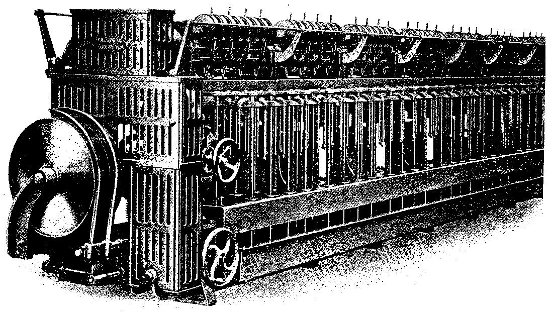
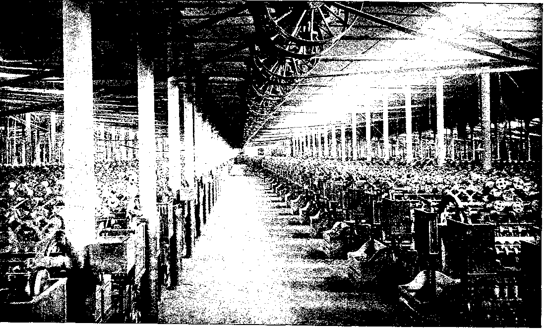
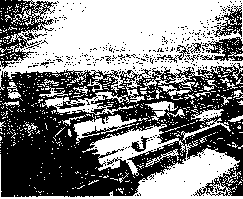
A photographical reproduction of a large spinning flat in one of the Indian jute mills appears in Fig. 20, showing particularly the wide "pass" between two long rows of spinning frames, and the method adopted of driving all the frames from a long line shaft. Spinning frames are usually double-sided, and each side may contain any practicable number of spindles; 64 to 80 spindles per side are common numbers.
The rove bobbins, several of which are clearly seen in Fig. 20, are brought from the roving frame and placed on the iron pegs of a creel (often called a hake) near the top of the spinning frame-actually above all moving parts of the machine. Each rove bobbin is free to rotate on its own peg as the rove from it is drawn downwards by the retaining rollers. The final drafting of the material takes place in this frame, and a considerable amount of twist is imparted to the drawn out material; the latter, now in the desired form and size of yarn, is wound simultaneously on to a suitable size and form of spinning bobbin.
When the rove emerges from the retaining rollers it is passed over a "breast-plate," and then is entered into the wide part of the conductor; it then leaves by the narrow part of the conductor by means of which part the rove is guided to the nip of the drawing rollers, The rove is, of course, drafted or drawn out between the retaining and drawing rollers according to the draft required, and the fibrous material, now in thread size is placed in a slot of the "thread-plate," then round the top of the flyer, round one of the arms of the flyer, through the eye or palm at the end of the flyer arm and on to the spinning bobbin. The latter is raised and lowered as in the roving frame by a builder motion, so that the yarn may be distributed over the full range between the ends or flanges.
Each spindle is driven separately by means of a tape or band which passes partially round the driving cylinder and the driven whorl of the spindle, and a constant relation obtains between the delivery of the yarn and the speed of the spindle during the operation of spinning any fixed count or type of yarn. In this connection, the parts resemble those in the roving frame, but from this point the functions of the two frames differ. The yarn has certainly to be wound upon the bobbin and at the same rate as it is delivered from the drawing or delivery rollers, but in the spinning frame the bobbin, which rotates on the spindle, is not driven positively, as in the roving frame, by wheel gearing; each spinning bobbin is actually driven by the yarn being pulled round by the arm of the flyer and just sufficient resistance is offered by the pressure or tension of the "temper band" and weight. The temper band is simply a piece of leather or hemp twine to which is attached a weight, and the other end of the leather or twine is attached to the builder rail.
The front part of the builder rail is provided with grooves into one of which the temper-band is placed so that the band itself is in contact with a groove near the base of the bobbin flange. A varying amount of resistance or tension on the bobbin is required in virtue of the varying size of the partially-filled bobbin, and this is obtained by placing the temper-band successively in different groves in the builder so that it will embrace a gradually increasing arc of the spinning bobbin, and thus impart a heavier drag or tension.
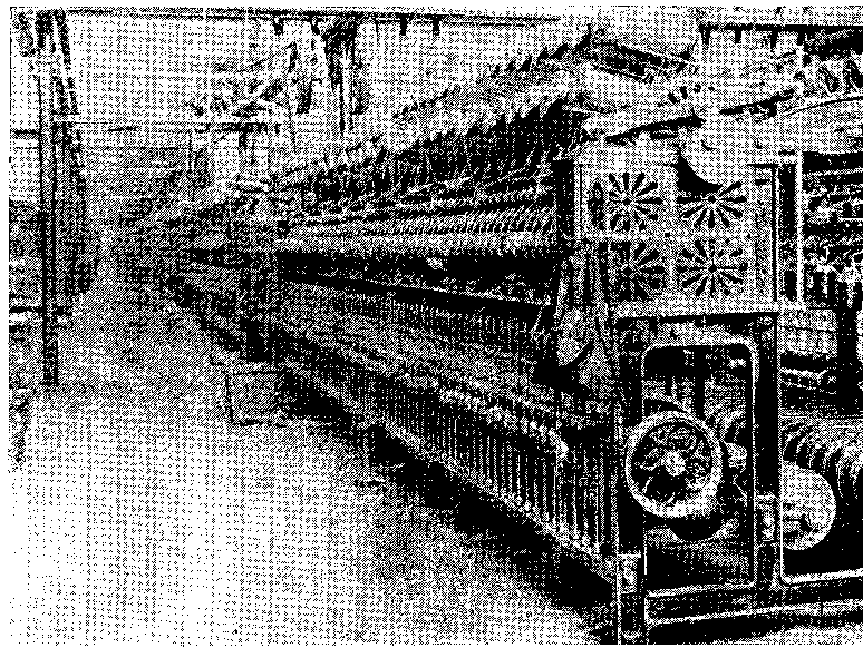
The spinning frames in Fig. 20 are arranged with the ends of the frame parallel to the pass, whereas the end frames in Fig. 21 are at right angles to the pass, and hence an excellent view of the chief parts is presented. The full rove bobbins are seen distinctly on the pegs of the creel in the upper part of the figure, and the rove yarns from these bobbins pass downwards, as already described, until they ultimately enter the eyes of the flyer arms to be directed to and wound upon the spinning bobbins. The flyers--at one time termed throstles--are clearly visible a little above the row of temper weights. The chief parts for raising the builder--cam lever, adjustable rod, chain and wheel--are illustrated at the end of the frame nearest the observer.
In regard to cloth manufacture, most yarns are utilized in the form they leave the spinning frame, that is, as single yarns. On the other hand, for certain branches of the trade, weaving included, it is necessary to take two, three, or more of these single yarns and to combine them by a process technically termed twisting, and sometimes "doubling" when two single yarns only are combined.
Although the commonest method, so far as weaving requirements go, is to twist two single yarns together to make a compound yarn, it is not uncommon to combine a much higher number, indeed, sixteen or more single yarns are often united for special purposes, but, when this number is exceeded, the operation comes under the heading of twines, ropes and the like. The twist or twine thus formed will have the number of yarns regulated by the levelness and strength required for the finished product. The same operation is conducted in the making of strands for cordage, but when a number of these twines are laid-up or twisted together, the name cord or rope is used to distinguish them.[1]
[Footnote 1: See Cordage and Cordage Hemp and Fibres, by T. Woodhouse and P. Kilgour.]
When two or three threads are united by twisting, the operation can be conducted in a twisting frame which differs little from a ordinary spinning frame, and hence need not be described. There may be, however, appliances embodying some system of automatic stop motion to bring the individual spindles to rest if one thread out of any group which are being combined happens to break. When several threads have to be twisted together, special types of twisting frames are employed; these special machines are termed "tube twisters," and the individual threads pass through holes suitably placed in a plate or disc before they reach the tube.
More or less elaborate methods of combining yarns are occasionally adopted, but the reader is advised to consult the above-mentioned work on Cordage and similar literature for detailed information.
When the yarn leaves the spinning frame, or the twisting frame, it is made up according to requirements, and the general operations which follow spinning and twisting are,--reeling, cop-winding, roll or spool winding, mill warping or link warping. The type or class of yarn, the purpose for which the yarn is to be used, or the equipment of the manufacturer, determines which of these methods should be used previous to despatching the yarn.
Reeling. Reeling is a comparatively simple operation, consisting solely of winding the yarns from the spinning or twisting bobbins on to a wide swift or reel of a suitable width and of a fixed diameter, or rather circumference. Indeed, the circumference of the reel was fixed by an Act of Convention of Estates, dating as far back as 1665 and as under:
"That no linen yarn be exported under the pain of confiscation, half to the King and half to the attacher."
"That linen yarn be sold by weight and that no reel be shorter than ten quarters."
The same size of reel has been adopted for all jute yarns. All such yarns which are to be dyed, bleached, or otherwise treated must be reeled in order that the liquor may easily penetrate the threads which are obviously in a loose state. There are systems of dyeing and bleaching yarns in cop, roll or beam form, but these are not employed much in the jute industry. Large quantities of jute yarns intended for export are reeled, partly because bundles form suitable bales for transport, and partly because of the varied operations and sizes of apparatus which obtain in foreign countries.
        YARN TABLE FOR JUTE YARNS


    90 inches,  or     2-1/2 yards    = 1 thread, or
                                         the circumference
                                         of the reel
   120 threads  or     300   yards    = 1 cut (or lea)
     2 cuts     or     600   yards    = 1 heer
    12 cuts     or   3,600   yards    = 1 standard hank
    48 cuts     or  14,400   yards    = 1 spyndle
Since jute yarns are comparatively thick, it is only the very finest yarns which contain 12 cuts per hank. The bulk of the yarn is made up into 6-cut hanks. If the yarn should be extra thick, even 6 cuts are too many to be combined, and one finds groups of 4 cuts, 3 cuts, 2 cuts, and even 1 cut. A convenient name for any group less than 12 cuts is a "mill-hank," because the number used is simply one of convenience to enable the mill-hank to be satisfactorily placed on the swift in the winding frame.
The reeling operation is useful in that it enables one to measure the length of the yarn; indeed, the operation of reeling, or forming the yarn into cuts and hanks, has always been used as the method of designating the count, grist or number of the yarn. We have already seen that the count of jute yarn is determined by the weight in lbs. of one spyndle (14,400 yds.).
For 8 lb. per spyndle yarn, and for other yarns of about the same count, it is usual to have provision for 24 spinning bobbins on the reel. As the reel rotates, the yarn from these 24 bobbins is wound round, say,
6 in. apart, and when the reel has made 120 revolutions, or 120 threads at each place from each bobbin, there will be 24 separate cuts of yarn on the reel. When 120 threads have been reeled as mentioned, a bell rings to warn the attendant that the cuts are complete; the reel is then stopped, and a "lease-band" is tied round each group of 120 threads.
A guide rod moves the thread guide laterally and slowly as the reeling operation is proceeding so that each thread or round may be in close proximity to its neighbour without riding on it, and this movement of the thread extends to approximately 6 in., to accommodate the 6 cuts which are to form the mill-hank.
Each time the reel has made 120 revolutions and the bell rings, the reeler ties up the several cuts in the width, so that when the mill-hank is complete, each individual cut will be distinct. In some case, the two threads of the lease-band instead of being tied, are simply crossed and recrossed at each cut, without of course breaking the yarn which is being reeled, although effectively separating the cuts. At the end of the operation (when the quantity of cuts for the mill-hank has been reeled) the ends of the lease-band are tied.
The object of the lease-band is for facilitating the operation of winding, and for enabling the length to be checked with approximate correctness.
When the reel has been filled with, say, twenty-four 6-cut hanks, there will evidently be 3 spyndles of yarn on the reel. The 24 mill-hanks are then slipped off the end of the reel, and the hanks taken to the bundling stool or frame. Here they, along with others of the same count, are made up into bundles which weigh from 54 lb. to 60 lb. according to the count of the yarn. Each bundle contains a number of complete hanks, and it is unusual to split a hank for the purpose of maintaining an absolutely standard weight bundle. Indeed, the bundles contain an even number of hanks, so that while there would be exactly 56 lb. per bundle of 7 lb. yarn, or 8 lb. yarn, there would be 60 lb in a bundle of 7-1/2 lb. yarn, and 54 lb. in a bundle of 9 lb. yarn.
The chief point in reeling is to ensure that the correct number of threads is in each cut, i.e. to obtain a "correct tell"; this ideal condition may be impracticable in actual work, but it is wise to approach it as closely as possible. Careless workers allow the reel to run on after one or more spinning bobbins are empty, and this yields what is known as "short tell." It is not uncommon to introduce a bell wheel with, say, 123 or 124 teeth, instead of the nominal 120 teeth, to compensate for this defect in reeling.
The actual spinning and twisting operations being thus completed, the yarns are ready to be combined either for more elaborate types of twist, or for the processes of cloth manufacture. In its simplest definition, a fabric consists of two series of threads interlaced in such way as to form a more or less solid and compact structure. The two series of threads which are interlaced receive the technical terms of warp and weft--in poetical language, warp and woof. The threads which form the length of the cloth constitute the warp, while the transverse threads are the weft.
The warp threads have ultimately to be wound or "beamed" on to a large roller, termed a weaver's beam, while the weft yarn has to be prepared in suitable shape for the shuttle. These two distinct conditions necessitate two general types of winding:
(a) Spool winding or bobbin winding for the warp yarns.
(b) Cop winding or pirn winding for the weft yarns.
For the jute trade, the bulk of the warp yarn is wound from the spinning bobbin on to large rolls or spools which contain from 7 to 8 lb. of yarn; the weft is wound from the spinning bobbin into cops which weigh approximately 4 to 8 ounces.
Originally all jute yarns for warp were wound on to flanged bobbins very similar to, but larger than, those which are at present used for the linen trade. The advent of the roll-winding machine marked a great advance in the method of winding warp yarns as compared with the bobbin winding method; indeed, in the jute trade, the latter are used only for winding from hank those yarns which have been bleached, dyed or similarly treated. Fig. 22 illustrates one of the modern bobbin winding machines for jute made by Messrs. Charles Parker, Sons & Co., Dundee. The finished product is illustrated by two full bobbins on the stand and close to a single empty bobbin. There are also two full bobbins in the winding position, and several hanks of yarn on the swifts. Each bobbin is driven by means of two discs, and since the drive is by surface contact between the discs and the bobbin, an almost constant speed is imparted to the yarn throughout the process. An automatic stop motion is provided for each bobbin; this apparatus lifts the bobbin clear of the discs when the bobbin is filled as exemplified in the illustration.
The distance between the flanges of the bobbin is, obviously, a fixed one in any one machine, and the diameter over the yarn is limited. On the other hand, rolls may be made of varying widths and any suitable diameter. And while a bobbin holds about 2 lb. of yarn, a common size of roll weighs, as already stated, from 7 to 8 lb. Such a roll measures, about 9 in. long and 8 in. diameter; hence for 8 lb. yarn, the roll capacity is 14,400 yards.
Rolls very much larger than the above are made on special machines adopted to wind about six rolls as shown in Fig. 23. It is built specially for winding heavy or thick yarns into rolls of 15 in. diameter and 14 in. length, and this particular machine is used mostly by rope makers and carpet manufacturers. One roll only is shown in the illustration, and it is winding the material from a 10 in. x 5 in. rove bobbin. The rove is drawn forward by surface or frictional contact between the roll itself and a rapidly rotating drum. The yarn guide is moved rapidly from side to side by means of the grooved cam on the left, the upright lever fulcrumed near the floor, and the horizontal rod which passes in front of the rolls and upon which are fixed the actual yarn guides. This rapid traverse, combined with the rotation of the rolls, enables the yarn to be securely built upon a paper or wooden tube; no flanges are required, and hence the initial cost as well as the upkeep of the foundations for rolls is much below that for bobbins.
Precisely the same principles are adopted for winding the ordinary 9 in. x 8 in. or 8 in. x 7 in. rolls for the warping and dressing departments. These rolls are made direct from the yarn on spinning bobbins, but the machines are usually double-sided, each side having two tiers; a common number of spools for one machine is 80.
The double tier on each side is practicable because of the small space required for the spinning bobbins. When, however, rolls are wound from hank, as is illustrated in Fig. 24, and as practised in several foreign countries even for grey yarn, one row only at each side is possible. Both types are made by each machine maker, the one illustrated in Fig. 24 being the product of Messrs. Charles Parker, Sons & Co., Dundee.
In all cases, the yarns are built upon tubes as mentioned, the wooden ones weighing only a few ounces and being practically indestructible, besides being very convenient for transit; indeed it looks highly probable that the use of these articles will still further reduce the amount of yarn exported in bundle form.
The machine illustrated in Fig. 24, as well as those by other makers, is very compact, easily adjustable to wind different sizes of rolls, can be run at a high speed, and possesses automatic stop motions, one for each roll.
A full roll and a partially-filled roll are clearly seen. A recent improvement in the shape of a new yarn drag device, and an automatic stop when the yarn breaks or the yarn on the bobbin is exhausted, has just been introduced on to the Combe-Barbour frame.
Weft Winding. A few firms wind jute weft yarn from the spinning bobbins on to pirns (wooden centres). The great majority of manufacturers, however, use cops for the loom shuttles. The cops are almost invariably wound direct from the spinning bobbins, the exception being coloured yarn which is wound from hank. There are different types of machines used for cop winding, but in every case the yarn is wound upon a bare spindle, and the yarn guide has a rapid traverse in order to obtain the well-known cross-wind so necessary for making a stable cop. The disposition of the cops in the winding operation is vertical, but while in some machines the tapered nose of the cop is in the high position and the spinning bobbin from which the yarn is being drawn is in the low position, in other machines these conditions are opposite. Thus, in the cop winding frame made by Messrs. Douglas Fraser & Sons, Ltd., Arbroath, and illustrated in Fig. 25, the spinning bobbins are below the cops, the tapered noses of the latter are upwards in their cones or shapers, and the yarn guides are near the top of the machine. This view shows about three-fourths of the full width of a 96-spindle machine, 48 spindles on each side, two practically full-length cops and one partially built. The illustration in Fig. 26 is the above-mentioned opposite type, and the one most generally adopted, with the spinning bobbins as shown near the top of the frame, the yarn guides in the low position, and the point or tapered nose of the cop pointing downwards. Six spindles only appear in this view, which represents the machine made by Messrs. Urquhart, Lindsay & Co., Ltd., Dundee, but it will be understood that all machines are made as long as desired within practicable and economic limits.
The spindles of cop machines are gear driven as shown clearly in Fig. 26; the large skew bevel wheels are keyed to the main shaft, while the small skew bevel wheels are loose on their respective spindles. The upper face of each small skew bevel wheel forms one part of a clutch; the other part of the clutch is slidably mounted on the spindle. When the two parts of the clutch are separated, as they are when the yarn breaks or runs slack, when it is exhausted, or when the cop reaches a predetermined length, the spindle stops; but when the two parts of the clutch are in contact, the small skew bevel wheel drives the clutch, the latter rotates the spindle, and the spindle in turn draws forward the yarn from the bobbin, and in conjunction with the rapidly moving yarn guide and the inner surface of the cone imparts in rapid succession new layers on the nose of the cop, and thus the formed layers of the latter increase the length proportionately to the amount of yarn drawn on, and the partially completed cop moves slowly away from its cup or cone until the desired length is obtained when the spindle is automatically stopped and the winding for that particular spindle ceases. Cops may be made of any length and any suitable diameter; a common size for jute shuttle is 10 in. long, and 1-5/8 in. diameter, and the angle formed by the two sides of the cone is approximately 30 degrees.
There are a few distinct methods of preparing warp threads on the weaver's beam. Stated briefly, the chief methods are--
1. The warp is made in the form of a chain on a warping mill,
and when the completed chain is removed from the mill it is
transferred on to the weaver's beam.
2. The warp is made in the form of a chain on a linking
machine, and then beamed on to a weaver's beam.
3. The warp yarns are wound or beamed direct from the large
cylindrical "rolls" or "spools" on to a weaver's beam.
4. The warp yarns are starched, dried and beamed
simultaneously on to a weaver's beam.
The last method is the most extensively adapted; but we shall describe the four processes briefly, and in the order mentioned.
For mill warping, as in No. 1 method, from 50 to 72 full spinning bobbins are placed in the bank or creel as illustrated to the right of each large circular warping mill in Fig. 27. The ends of the threads from these bobbins are drawn through the eyes of two leaves of the "heck," and all the ends tied together. The heck, or apparatus for forming what is known as the weaver's lease, drawer's lease, or thread-by-thread lease, is shown clearly between the bobbin bank and the female warper in the foreground of the illustration. The heck is suspended by means of cords, or chains, and so ranged that when the warping mill is rotated in one direction the heck is lowered gradually between suitable slides, while when the mill is rotated in the opposite direction the heck is raised gradually between the same slides. These movements are necessary in order that the threads from the bobbins may be arranged spirally round the mill and as illustrated clearly on all the mills in the figure. The particular method of arranging the ropes, or the gearing if chains are used, determines the distance between each pair of spirals; a common distance is about 1-1/2 in. There are about 42 spirals or rounds on the nearest mill in Fig. 27, and this number multiplied by the circumference of the mill represents the length of the warp.
At the commencement, the heck is at the top, and when the weaver's lease has been formed on the three pins near the top of the mill with the 50 to 72 threads (often 56), the mill is rotated by means of the handle and its connections shown near the bottom of the mill. As the mill rotates, the heck with the threads descends gradually and thus the group of threads is disposed spirally on the vertical spokes of the mill until the desired length of the warp is reached. A beamer's lease or "pin lease" is now made on the two lower pegs; there may be two, three, four or more threads in each group of the pin lease; a common number is 7 to 9. When this pin lease has been formed, one section of the warp has been made, the proportion finished being (50 to 72)/x where x is the total number of threads required for the cloth. The same kind of lease must again be made on the same two pins at the bottom for the beginning of the next section of 50 to 72 threads, and the mill rotated in the opposite direction in order to draw up the heck, and to cause the second group of 50 to 72 threads to be arranged spirally and in close touch with the threads of the first group. When the heck reaches the top of the mill, the single-thread lease is again made, all the threads passed round the end pin, and then all is ready for repeating the same two operations until the requisite number of threads has been introduced on to the mill. If it is impossible to accommodate all the threads for the cloth on the mill, the warp is made in two or more parts or chains. It will be noticed that the heck for the nearest mill is opposite about the 12th round of threads from the bobbin, whereas the heck for the second mill is about the same distance from the top. A completed warp or chain is being bundled up opposite the third mill. When the warp is completed it is pulled off the mill and simultaneously linked into a chain.
A very similar kind of warp can be made more quickly, and often better, on what is termed the linking machine mentioned in No. 2 method. Such a machine is illustrated in Fig. 28, and the full equipment demands the following four distinct kinds of apparatus--a bank capable of holding approximately 300 spools, a frame for forming the weaver's lease and the beamer's lease, machine for drawing the threads from the spools in the bank and for measuring the length and marking the warp at predetermined intervals, and finally the actual machine which links the group of threads in the form of a chain.
In Fig. 28 part of the large bank, with a few rows of spools, is shown in the extreme background. The two sets of threads, from the two wings of the bank, are seen distinctly, and the machine or frame immediately in front of the bank is where the two kinds of lease are made when desired, i.e. at the beginning and at the end of the warp. Between this leasing frame and the linking machine proper, shown in the foreground, is the drawing, measuring and marking machine. Only part of this machine is seen--the driving pulleys and part of the frame adjoining them. All these frames and machines are necessary, but the movements embodied in them, or the functions which they perform, are really subsidiary to those of the linker shown in the foreground of Fig. 28.
Although the linking machine is composed of only a few parts, it is a highly-ingenious combination of mechanical parts; these parts convert the straight running group of 300 threads into a linked chain, and the latter is shown distinctly descending from the chute on to the floor in the figure. Precisely the same kind of link is made by the hand wrappers when the warps indicated in Fig. 27 are being withdrawn from the mills. Two completed chains are shown tied up in Fig. 28, and a stock of rolls or spools appear against the wall near the bank.
The completed chain from the warping mill or the linking machine is now taken to the beaming frame, and after the threads, or rather the small groups of threads, in the pin lease have been disposed in a kind of coarse comb or reed, termed an veneer or radial, and arranged to occupy the desired width in the veneer, they are attached in some suitable way to the weaver's beam. The chain is held taut, and weights applied to the presser on the beam while the latter is rotated. In this way a solid compact beam of yarn is obtained. The end of the warp--that one that goes on to the beam last--contains the weaver's lease, and when the completed beam is removed from the beaming or winding-on frame, this single-thread lease enables the next operative to select the threads individually and to draw the threads, usually single, but sometimes in pairs, in which case the lease would be in pairs, through the eyes of the camas or HEALDS, or to select them for the purpose of tying them to the ends of the warp in the loom, that is to the "thrum" of a cloth which has been completed.
Instead of first making a warp or chain on the warping mill, or on the linking machine, and then beaming such warp on to the weaver's beam or loom beam as already described, two otherwise distinct processes of warping and beaming may be conducted simultaneously. Thus, the total number of threads required for the manufacture of any particular kind of cloth--unless the number of threads happens to be very high--may be wound on to the loom beam direct from the spools. Say, for example, a warp was required to be 600 yards long, and that there should be 500 threads in all. Five hundred spools of warp yarn would be placed in the two wings of a V-shaped bank, and the threads from these spools taken in regular order, and threaded through the splits or openings of a reed which is placed in a suitable position in regard to the winding-on mechanism. Some of the machines which perform the winding-on of the yarn are comparatively simple, while others are more or less complicated. In some the loom beam rotates at a fixed number of revolutions per minute, while in others the beam rotates at a gradually decreasing number of revolutions per minute. One of the latter types made by MESSRS Urquhart, Lindsay & Co., Ltd., Dundee, is illustrated in Fig. 29, and the mechanism displayed is identical with that employed for No. 4 method of preparing warps.
The V-shaped bank with its complement of spools (500 in our example) would occupy a position immediately to the left of Fig. 29. The threads would pass through a reed and then in a straight wide sheet between the pair of rollers, these parts being contained in the supplementary frame on the left. A similar frame appears on the extreme right of the figure, and this would be used in conjunction with another V-shaped bank, not shown, but which would occupy a position further to the right, i.e. if one bank was not large enough to hold the required number of spools. The part on the extreme right can be ignored at present.
The threads are arranged in exactly the same way as indicated in Fig. 28 from the bank to the reed in front of the rollers in Fig. 29, and on emerging from the pair of rollers are taken across the stretch between the supplementary frame and the main central frame, and attached to the weavers beam just below the pressing rollers. It may be advisable to have another reed just before the beam, so that the width occupied by the threads in the beam may be exactly the same as the width between the two flanges of the loom beam.
The speed of the threads is determined by the surface speed of the two rollers in the supplementary frame, the bottom roller being positively driven from the central part through the long horizontal shaft and a train of wheels caged in as shown. The loom beam, which is seen clearly immediately below the pressing rollers, is driven by friction because the surface speed of the yarn must be constant; hence, as the diameter over the yarn on the beam increases, the revolutions per minute of the beam must decrease, and a varying amount of slip takes place between the friction-discs and their flannels.
As the loom beam rotates, the threads are arranged in layers between the flanges of the loom beam. Thus, the 500 threads would be arranged side by side, perhaps for a width of 45 to 46 in., and bridging the gap between the flanges of the beam; the latter is thus, to all intents and purposes, a very large bobbin upon which 500 threads are wound at the same time, instead of one thread as in the ordinary but smaller bobbin or reel. It will be understood that in the latter case the same thread moves from side to side in order to bridge the gap, whereas in the former case each thread maintains a fixed position in the width.
The last and most important method of making a warp, No. 4 method, for the weaver is that where, in addition to the simultaneous processes of warping and beaming as exemplified in the last example, all the threads are coated with some suitable kind of starch or size immediately they reach the two rollers shown in the supplementary frame in Fig. 29. The moistened threads must, however, be dried before they reach the loom beam. When a warp is starched, dried and beamed simultaneously, it is said to be "dressed."
In the modern dressing machine, such as that illustrated in Fig. 30, there are six steam-heated cylinders to dry the starched yarns before the latter reach the loom beams. Both banks, or rather part of both, can be seen in this view, from which some idea will be formed of the great length occupied. Several of the threads from the spools in the left bank are seen converging towards the back reed, then they pass between the two rollers--the bottom one of which is partially immersed in the starch trough--and forward to the second reed. After the sheet of threads leaves the second reed, it passes partially round a small guide roller, then almost wholly round each of three cylinders arranged °o°, and finally on to the loom beam. Each cylinder is 4 feet diameter, and three of them occupy a position between the left supplementary frame, and the central frame in Fig. 29, while the remaining three cylinders are similarly disposed between the central frame and the supplementary frame of the right in the same illustration.
The number of steam-heated cylinders, and their diameter, depend somewhat upon the type of yarn to be dressed, and upon the speed which it is desired to run the yarn. A common speed for ordinary-sized jute is from 18 to 22 yards per minute.
A different way of arranging the cylinders is exemplified in Fig. 31. This view, which illustrates a machine made by Messrs. Charles Parker, Sons & Co., Dundee, has been introduced to show that if the warps under preparation contain a comparatively few threads, or if the banks are made larger than usual, two warps may be dressed at the same time. In such a case, three cylinders only would be used for each warp, and the arrangement would be equivalent to two single dressing machines. The two weaver's beams, with their pressing rollers, are shown plainly in the centre of the illustration. Some machines have four cylinders, others have six, while a few have eight. A very similar machine to that illustrated in Fig. 31 is made so that all the six cylinders may be used to dry yarns from two banks, and all the yarns wound on to one weaver's beam, or all the yarns may be wound on to one of the beams in the machine in Fig. 31 if the number of threads is too many for one bank.
Suppose it is desired to make a warp of 700 threads instead of 500, as in the above example; then 350 spools would be placed in each of the two banks, the threads disposed as already described to use as much of the heating surface of the cylinder as possible, and one sheet of threads passed partially round what is known as a measuring roller. Both sheets of threads unite into one sheet at the centre of the machine in Fig. 31, and pass in this form on to one of the loom beams.
It has already been stated that the lower roller in the starch box is positively driven by suitable mechanism from the central part of the machine, Fig. 29, while the upper roller, see Fig. 30, is a pressing roller and is covered with cloth, usually of a flannel type. Between the two rollers the sheet of 350 threads passes, becomes impregnated with the starch which is drawn up by the surface of the lower roller, and the superfluous quantity is squeezed out and returns to the trough, or joins that which is already moving upwards towards the nip of the rollers. The yarn emerges from the rollers and over the cylinders at a constant speed, which may be chosen to suit existing conditions, and it must also be wound on to the loom beam at the same rate. But since the diameter of the beam increases each revolution by approximately twice the diameter of the thread, it is necessary to drive the beam by some kind of differential motion.
The usual way in machines for dressing jute yarns is to drive the beam support and the beam by means of friction plates. A certain amount of slip is always taking place--the drive is designed for this purpose--and the friction plates are adjusted by the yarn dresser during the operation of dressing to enable them to draw forward the beam, and to slip in infinitesimal sections, so that the yarn is drawn forward continuously and at uniform speed.
During the operation, the measuring roller and its subsequent train of wheels and shafts indicates the length of yarn which has passed over, also the number of "cuts" or "pieces" of any desired length; in addition, part of the measuring and marking mechanism uses an ink-pad to mark the yarn at the end of each cut, such mark to act as a guide for the weaver, and to indicate the length of warp which has been woven. Thus if the above warp were intended to be five cuts, each 120 yards, or 600 yards in all, the above apparatus would measure and indicate the yards and cuts, and would introduce a mark at intervals of 120 yards on some of the threads. And all this is done without stopping the machine. At the time of marking, or immediately before or after, just as desired, a bell is made to ring automatically so that the attendant is warned when the mark on the warp is about to approach the loom beam. This bell is shown in Fig. 29, near the right-hand curved outer surface of the central frame.
As in hand warping or in linking, a single-thread lease is made at the end of the desired length of warp, or else what is known as a pair of "clasp-rods" is arranged to grip the sheet of warp threads.
After the loom beam, with its length of warp, has been removed from the machine, the threads are either drawn through the eyes or mails of the cambs (termed gears, healds or heddles in other districts) and through the weaving reed, or else they are tied to the ends of the threads of the previous warp which, with the weft, has been woven into cloth. These latter threads are still intact in the cambs and reed in the loom.
If all the threads of the newly-dressed warp can be tied on to the ends of the warp which has been woven, it is only necessary, when the tying-on process is completed, to rotate the loom beam slowly, and simultaneously to draw forward the threads until all the knots have passed through the cambs and the reed, and sufficiently far forward to be clear of the latter when it approaches its full forward, or beating up, position during the operation of weaving.
If, on the other hand, the threads of the newly-dressed, or newly-beamed, warp had to be drawn-in and reeded, these operations would be performed in the drawing-in and reeding department, and, when completed, the loom beam with its attached warp threads, cambs and reed, would be taken bodily to the loom where the "tenter," "tackler" or "tuner" adjusts all the parts preparatory to the actual operation of weaving. The latter work is often termed "gaiting a web."
There is a great similarity in many of the operations of weaving the simpler types of cloth, although there may be a considerable difference in the appearance of the cloths themselves. In nearly all the various branches of the textile industry the bulk of the work in the weaving departments of such branches consists of the manufacture of comparatively simple fabrics. Thus, in the jute industry, there are four distinct types of cloth which predominate over all others; these types are known respectively as hessian, bagging, tarpauling and sacking. In addition to these main types, there are several other simple types the structure of which is identical with one or other of the above four; while finally there are the more elaborate types of cloth which are embodied in the various structures of carpets and the like.
It is obviously impossible to discuss the various makes in a work of this kind; the commoner types are described in Jute and Linen Weaving Calculations and Structure of Fabrics; and the more elaborate ones, as well as several types of simple ones, appear in Textile Design: Pure and Applied, both by T. Woodhouse and T. Milne.
Six distinct types of jute fabrics are illustrated in Fig. 32. The technical characteristics of each are as follows--
H.--An ordinary "HESSIAN" cloth made from comparatively fine single warp and single weft, and the threads interlaced in the simplest order, termed "plain weave." A wide range of cloths is made from the scrims or net-like fabrics to others more closely woven than that illustrated.
B.--A "BAGGING" made from comparatively fine single warp arranged in pairs and then termed "double warp." The weft is thick, and the weave is also plain.
T.--A "TARPAULING" made from yarns similar to those in bagging, although there is a much wider range in the thickness of the weft. It is a much finer cloth than the typical bagging, but otherwise the structures are identical.
S.--A striped "SACKING" made from comparatively fine warp yarns, usually double as in bagging, but occasionally single, with medium or thick weft interwoven in 3-leaf or 4-leaf twill order. The weaves are shown in Fig. 33.
C.--One type of "CARPET" cloth made exclusively from two-ply or two-fold coloured warp yarns, and thick black single weft yarns. The threads and picks are interwoven in two up, two down twill, directed to right and then to left, and thus forming a herring-bone pattern, or arrow-head pattern.
P.-An uncut pile fabric known as "BRUSSELLETTE." The figuring warp is composed of dyed and printed yarns mixed to form an indefinite pattern, and works in conjunction with a ground warp and weft. The weave is again plain, although the structure of the fabric is quite different from the other plain cloths illustrated. The cloth is reversible, the two sides being similar structure but differing slightly in colour ornamentation.
As already indicated, there are several degrees of fineness or coarseness in all the groups, particularly in the types marked H, B, T and S. The structure or weave in all varieties of any one group is constant and as stated.
All the weaves are illustrated in the usual technical manner in Fig. 33, and the relation between the simplest of these weaves and the yarns of the cloth is illustrated in Fig. 34. In Fig. 33, the unit weaves in A, B, C, D, E and F are shown in solid squares, while the repetitions of the units in each case are represented by the dots.
A is the plain weave, 16 units shown, and used for fabrics H and P, Fig. 32.
B is the double warp plain wave, 8 units shown, and shows the method of interlacing the yarns h patterns B and T, Fig. 32. When the warp is made double as indicated in weave B, the effect in the cloth can be produced by using the mechanical arrangements employed for weave A. Hence, the cloths H, B and T can be woven without any mechanical alteration in the loom.
C is the 3-leaf double warp sacking weave and shows 4 units; since each pair of vertical rows of small squares consists of two identical single rows, they may be represented as at D. The actual structure of the cloth S in Fig. 32 is represented on design paper at C, Fig. 33.
D is the single warp 3-leaf sacking weave, 4 units shown, but the mechanical parts for weaving both C and D remain constant.
E is the double warp 4-leaf sacking, 2 units shown, while
F is the single warp 4-leaf sacking, 4 units shown.
The patterns or cloths for E and F are not illustrated.
G is a "herring-bone" design on 24 threads and 4 picks, two units shown. It is typical of the pattern represented at C, Fig. 32, and involves the use of 4 leaves in the loom.
The solid squares in weave A, Fig. 33, are reproduced in the left-hand bottom corner of Fig. 34. A diagrammatic plan of a plain cloth produced by this simple order of interlacing is exhibited in the upper part by four shaded threads of warp and four black picks of weft (the difference is for distinction only). The left-hand intersection shows one thread interweaving with all the four picks, while the bottom intersection shows all the four threads interweaving with one pick. The two arrows from the weave or design to the thread and pick respectively show the connection, and it will be seen that a mark (solid) on the design represents a warp thread on the surface of the cloth, while a blank square represents a weft shot on the surface, and vice versa.
A weaving shed full of various types of looms, and all driven by belts from an overhead shaft, is illustrated in Fig. 35. The loom in the foreground is weaving a 3-leaf sacking similar to that illustrated at S, Fig. 32. while the appearance of a full weaver's warp beam is shown distinctly in the second loom in Fig. 35. There are hundreds of looms in this modern weaving shed.
During the operation of weaving, the shuttle, in which is placed a cop of weft, similar to that on the cop winding machine in Fig. 25, and with the end of the weft threaded through the eye of the shuttle, is driven alternately from side to side of the cloth through the opening or "shed" formed by two layers of the warp. The positions of the threads in these two layers are represented by the designs, see Fig. 33, and while one layer occupies a high position in the loom the other layer occupies a low position. The threads of the warp are placed in these two positions by the leaves of the camb (termed healds and also gears in other districts) and it is between these two layers that the shuttle passes, forms a selvage at the edge each time it makes a journey across, and leaves a trail or length of weft each journey. The support or lay upon which the shuttle travels moves back to provide room for the shuttle to pass between the two layers of threads, and after the shuttle reaches the end of each journey, the lay with the reed comes forward again, and thus pushes successively the shots of weft into close proximity with the ones which preceded.
The order of lifting and depressing the threads of the warp is, as already stated, demonstrated on the design paper in Fig. 33, and the selected order determines, in the simplest cases, the pattern on the surface of the cloth when the warp and weft yarns are of the same colour. A great diversity of pattern can be obtained by the method of interlacing the two sets of yarn, and a still greater variety of pattern is possible when differently-coloured threads are added to the mode of interlacing.
To illustrate the contrast in the general appearance of a weaving shed in which all the looms are driven by belts from overhead shafting as in Fig. 35, and in a similar shed in which all the looms are individually driven by small motors made by the English Electric Co., Ltd. we introduce Fig. 36. This particular illustration shows cotton weaving shed, but precisely the same principle of driving is being adopted in many jute factories.
A great variety of carpet patterns of a similar nature to that illustrated at C, Fig. 32, can be woven in looms such as those illustrated in Fig. 35; indeed, far more elaborate patterns than that mentioned and illustrated are capable of being produced in these comparatively simple looms. When, however, more than 4 leaves are required for the weaving of a pattern, a dobby loom, of the nature of that shown in Fig. 37, is employed; this machine is made by Messrs. Charles Parker, Sons & Co., Ltd., Dundee. The dobby itself, or the apparatus which lifts the leaves according to the requirements of the design, is fixed on the upper part of the frame-work, and is designed to control 12 leaves, that is, it operates 12 leaves, each of which lifts differently from the others.
A considerable quantity of Wilton and Brussels carpets is made from jute yarns, and Fig. 38 illustrates a loom at work on this particular branch of the trade. The different colours of warp for forming the pattern me from small bobbins in the five frames at the back of the loom (hence the term 5-frame Brussels or Wilton carpet) and the ends passed through "mail eyes" and then through the reed. The design is cut on the three sets of cards suspended in the cradles in the front of the loom, and these cards operate on the needles of the jacquard machine to raise those colours of yarn which e necessary to produce the colour effect in the cloth t correspond with the colour effect on the design paper made by the designer. This machine weaves the actual Brussels and Wilton fabrics, and these cloths are quite different from that illustrated at P, Fig. 32. In both fabrics, however, ground or foundation warps are required. It need hardly be said that there is a considerable difference between the two types of cloth, as well as between the designs and the looms in which they are woven.[2]
[Footnote 2: For structure of carpets, see pp. 394-114, Textile Design: Pure and Applied, by T. Woodhouse and T. Milne.]
In the weaving department there are heavy warp beams to be placed in the looms, and in the finishing department there are often heavy rolls of cloth to be conveyed from the machines to the despatch room. Accidents often happen when these heavy packages, especially the warp beams, are being placed in position. In order to minimize the danger to workpeople and to execute the work more quickly and with fewer hands, some firms have installed Overhead Runway Systems, with suitable Lifting Gear, by means of which the warp beams are run from the dressing and drawing-in departments direct to the looms, and then lowered quickly and safely into the bearings. Such means of transport are exceedingly valuable where the looms are set close to each other and where wide beams are employed; indeed, they are valuable for all conditions, and are used for conveying cloth direct from the looms as well as warp beams to the looms. Fig. 39 shows the old wasteful and slow method of transferring warp beams from place to place, while Fig. 40 illustrates the modern and efficient method. The latter figure illustrates one kind of apparatus, supplied by Messrs. Herbert Morris, Ltd., Loughborough, for this important branch of the industry.
The finishing touches are added to the cloth after the latter leaves the loom. The first operation is that of inspecting the cloth, removing the lumps and other undesirables, as well as repairing any damaged or imperfect parts. After this, the cloth is passed through a cropping machine the function of which is to remove all projecting fibres from the surface of the cloth, and so impart a clean, smart appearance. It is usual to crop both sides of the cloth, although there are some cloths which require only one side to be treated, while others again miss this operation entirely.
A cropping machine is shown in the foreground of Fig. 41, and in this particular case there are two fabrics being cropped or cut at the same time; these happen to be figured fabrics which have been woven in a jacquard loom similar to that illustrated in Fig. 38. The fabrics are, indeed, typical examples of jute Wilton carpets. The illustration shows one of the spiral croppers in the upper part of the machine in Fig. 41. Machines are made usually with either two or four of such spirals with their corresponding fixed blades.
The cloth is tensioned either by threading it over and under a series of stout rails, or else between two in a specially adjustable arrangement by means of which the tension may be varied by rotating slightly the two rails so as to alter the angle formed by the cloth in contact with them. This is, of course, at the feed side; the cloth is pulled through the machine by three rollers shown distinctly on the right in Fig. 42. This view illustrates a double cropper in which both the spirals are controlled by one belt. As the cloth is pulled through, both sides of it are cropped by the two spirals.[3] When four spirals are required, the frame is much wider, and the second set of spirals is identical with those in the machines illustrated.
[Footnote 3: For a full description of all finishing processes, see The Finishing of Jute and Linen Fabrics, by T. Woodhouse. (Published by Messrs. Emmott & Co., Ltd., Manchester.)]
The cropped cloth is now taken to the clamping machine, and placed on the floor on the left of the machine illustrated in Fig. 43, which represents the type made by Messrs. Charles Parker, Sons &, Co., Dundee. The cloth is passed below a roller near to the floor, then upwards and over the middle roller, backwards to be passed under and over the roller on the left, and then forwards to the nip of the pulling rollers, the bottom one of which is driven positively by means of a belt on the pulleys shown. While the cloth is pulled rapidly through this machine, two lines of fine jets spray water on to the two sides of the fabric to prepare it for subsequent processes in which heat is generated by the nature of the finishing process. At other times, or rather in other machines, the water is distributed on the two sides of the cloth by means of two rapidly rotating brushes which flick the water from two rollers rotating in a tank of water at a fixed level. In both cases, both sides of the fabric are "damped," as it is termed, simultaneously. The damped fabric is then allowed to lie for several hours to condition, that is, to enable the moisture to spread, and then it is taken to the calender.
The calenders for jute almost invariably contain five different rollers, or "bowls," as they are usually termed; one of these bowls, the smallest diameter one, is often heated with steam. A five-bowl calender is shown on the extreme right in Fig. 41, and in the background, while a complete illustration of a modern 5-bowl calender, with full equipment, and made by Messrs. Urquhart, Lindsay & Co., Ltd., Dundee, appears in Fig. 44.
The cloth is placed on the floor between the two distinct parts of the calender, threaded amongst the tension rails near the bottom roller or bowl, and then passed over two or more of the bowls according to the type of finish desired. For calender finish, the bowls flatten the cloth by pressing out the threads and picks, so that all the interstices which appear in most cloths as they leave the loom, and which are exaggerated in the plan view in Fig. 34, are eliminated by this calendering action. The cloth is then delivered at the far side of the machine in Fig. 44. If necessary, the surface speed of the middle or steam-heated roller may differ from the others so that a glazed effect--somewhat resembling that obtained by ordinary ironing--is imparted to the surface of the fabric. The faster moving roller is the steam-heated one. For ordinary calender finish, the surface speed of all the rollers is the same.
Another "finish" obtained on the calender is known as "chest finish" or "round-thread finish." In this case, the whole length of cloth is wound either on to the top roller, or the second top one, Fig. 44, and while there is subjected to the degree of pressure required; the amount of pressure can be regulated by the number of weights and the way in which the tension belt is attached to its pulley. The two sets of weights are seen clearly on the left in Fig. 44, and these act on the long horizontal levers, usually to add pressure to the dead weight of the top roller, but occasionally, for very light finishes, to decrease the effective weight of the top bowl. After the cloth has been chested on one or other of the two top bowls, it is stripped from the bowl on to a light roller shown clearly with its belt pulley in Fig. 41.
There are two belt pulleys shown on the machine in Fig. 44; one is driven by an open belt, and the other by a crossed belt. Provision is thus made for driving the calender in both directions. The pulleys are driven by two friction clutches, both of which are inoperative when the set-on handle is vertical as in the figure. Either pulley may be rotated, however, by moving the handle to a oblique position.
The compound leverage imparted to the bearings of the top bowl, and the weights of the bowls themselves, result in the necessary pressure, and this pressure may be varied according to the number of small weights used. The heaviest finish on the calender, i.e. the chest-finish on the second top roller, imitates more or less the "mangle finish."
A heavy hydraulic mangle with its accumulator and made by Messrs. Urquhart, Lindsay & Co., Ltd., Dundee, is illustrated in Fig. 45. The cloth is wound or beamed by the mechanism in the front on to what is termed a "mangle pin"; it is reality a thick iron bowl; when the piece is beamed, it is automatically moved between two huge rollers, and hydraulic pressure applied. Four narrow pieces are shown in Fig. 45 on the pin, and between the two rollers. There are other four narrow pieces, already beamed on another pin, in the beaming position, and there is still another pin at the delivery side with a similar number of cloths ready for being stripped. The three pins are arranged thus o°o, and since all three are moved simultaneously, when the mangling operation is finished, each roller or pin is moved through 120°. Thus, the stripped pin will be placed in the beaming position, the beamed pin carried into the mangling position, and the pin with the mangled cloth taken to the stripping position.
While the operation of mangling is proceeding, the rollers move first in one direction and then in the other direction, and this change of direction is accomplished automatically by mechanism situated between the accumulator and the helical-toothed gearing seen at the far end of the mangle. And while this mangling is taking place, the operatives are beaming a fresh set, while the previously mangles pieces are being stripped by the plaiting-down apparatus which deposits the cloth in folds. This operation is also known as "cuttling" or "faking." It will be, understood that a wide mangle, such as that illustrated in Fig. 45. is constructed specially for treating wide fabrics, and narrow fabrics are mangled on it simply because circumstances and change of trade from time to time demand it.
The high structure on the left is the accumulator, the manipulation of this and the number of wide weights which are ingeniously brought into action to act on the plunger determine the pressure which is applied to the fabrics between the bowls or rollers.
Cloths both from the calender and the mangle now pass through a measuring machine, the clock of which records the length passed through. There are usually two hands and two circles of numbers on the clock face; one hand registers the units up to 10 on one circle of numbers, while the slower-moving hand registers 10, 20, 30, up to 100. The measuring roller in these machines is usually one yard in circumference.
If the cloth in process of being finished is for use as the backing or foundation of linoleum, it is invariably wound on to a wooden centre as it emerges from the bowls of the calender, measured as well, and the winding-on mechanism is of a friction drive somewhat similar to that mentioned in connection with the dressing machine. Cloths for this purpose are often made up to 600 yards in length; indeed, special looms, with winding appliances, have been constructed to weave cloths up to 2,000 yards in length. Special dressing machines and loom beams have to be made for the latter kind. When the linoleum backing is finished at the calender, both cloth and centre are forwarded direct to the linoleum works. The empty centres are returned periodically.
Narrow-width cloths are often made up into a roll by means of a simple machine termed a calenderoy, while somewhat similar cloth, and several types of cloths of much wider width, are lapped or folded by special machines such as that illustrated in Fig. 46. The cloth passes over the oblique board, being guided by the discs shown, to the upper part of the carrier where it passes between the two bars. As the carrier is oscillated from side to side (it is the right hand side in the illustration) the cloth is piled neatly in folds on the convex table. The carriers may be adjusted to move through different distances, so that any width or length of fold, between limits, may be made.
Comparatively wide pieces can be folded on the above machine, but some merchants prefer to have wide pieces doubled lengthwise, and this is done by machines of different kinds. In all cases, however, the operation is termed "crisping" in regard to jute fabrics. Thus, Fig. 47, illustrates one type of machine used for this purpose, and made by Messrs. Urquhart, Lindsay & Ca., Ltd., Dundee. The full-width cloth on the right has obviously two prominent stripes--one near each side. The full width cloth passes upwards obliquely a triangular board, and when the cloth reaches the apex it is doubled and passed between two bars also set obliquely on the left. The doubled piece now passes between a pair of positively driven drawing rollers, and is then "faked," "cuttled," or pleated as indicated. The machine thus automatically, doubles the piece, and delivers it as exemplified in folds of half width. In other industries, this operation is termed creasing and, rigging. Some of the later types of crisping or creasing machines double the cloth lengthwise as illustrated in Fig. 47, and, in addition, roll it at the same time instead of delivering it in loose folds.
If the cloth is intended to be cut up into lengths, say for the making of bags of various kinds, and millions of such bags are made annually, it is cut up into the desired lengths, either by hand, semi-mechanically, or wholly mechanically, and then the lengths are sewn at desired places by sewing machines, and in various ways according to requirements.
Fig. 48 illustrates one of the semi-mechanical machines for this purpose; this particular type being made by Messrs. Urquhart, Lindsay & Co., Ltd., Dundee. About eight or nine different cloths are arranged in frames behind the cutting machine, and the ends of these cloths passed between the horizontal bars at the back of the machine. They are then led between the rollers, under the cutting knife, and on to the table. The length of cloth is measured as it passes between the rollers, and different change pinions are supplied so that practically any length may be cut. Eight or nine lengths are thus passed under the knife frame simultaneously, and when the required length has been delivered, the operative inserts the knife in the slot of the knife frame, and pushes it forward by means of the long handle shown distinctly above the frame and table. He thus cuts eight or nine at a time, after which a further length is drawn forward, and the cycle repeated. Means are provided for registering the number passed through; from 36,000 yards to 40,000 yards can be treated per day.
The bags may be made of different materials, e.g. the first four in Fig. 32. When hessian cloth, II, Fig. 32, is used, the sewing is usually done by quick-running small machines, such as the Yankee or Union; each of these machines is capable of sewing more than 2,000 bags per day. For the heavier types of cloth, such as sacking, S, Fig. 32, the sewing is almost invariably done by the Laing or overhead sewing machine, the general type of which is illustrated in Fig. 49, and made by Mr. D. J. Macdonald, South St. Roque's Works, Dundee. This is an absolutely fast stitch, and approximately 1,000 bags can be sewn in one day.
The distinctive marks in bags for identification often take the form of coloured stripes woven in the cloth, and as illustrated at S, Fig. 32. It is obvious that a considerable variety can be made by altering the number of the stripes, their position, and their width, while if different coloured threads appear in the same cloth, the variety is still further increased.
Many firms, however, prefer to have their names, trade marks, and other distinctive features printed on the bags; in these cases, the necessary particulars are printed on the otherwise completed bag by a sack-printing machine of the flat-bed or circular roller type. The latter type, which is most largely used, is illustrated in Fig. 50. It is termed a two-colour machine, and is made by Mr. D. J. Macdonald, Dundee; it will be observed that there are two rollers for the two distinct colours, say red and black. Occasionally three and four-colour machines are used, but the one-colour type is probably the most common.
The ownership of the bags can thus be shown distinctly by one of the many methods of colour printing, and if any firm desires to number their bags consecutively in order to provide a record of their stock, or for any other purpose, the bags may be so numbered by means of a special numbering machine, also made by Mr. D. J. Macdonald.
The last operation, excluding the actual delivery of the goods, is that of packing the pieces or bags in small compass by means of a hydraulic press. The goods are placed on the lower moving table upon a suitable wrapping of some kind of jute cloth; when the requisite quantity has been placed thereon, the top and side wrappers are placed in position, and the pumps started in order to raise the bottom table and to squeeze the content between it and the top fixed table. From 1 1/2 ton to 2 tons per square inch is applied according to the nature of the goods and their destination. While the goods are thus held securely in position between the two plates, the wrappers a sewn together. Then specially prepared hoops or metal bands are placed round the bale, and an ingenious and simple system, involving a buckle and two pins, adopted for fastening the bale. The ends of the hoop or band are bent in a small press, and these bent ends are passed through a rectangular hole in the buckle and the pins inserted in the loops. As soon as the hydraulic pressure is removed, the bale expands slightly, and the buckled hoop grips the bale securely.
Such is in brief the routine followed in the production of the fibre, the transformation of this fibre, first into yarn, and then into cloth, and the use of the latter in performing the function of the world's common carrier.

Advertisement: Thomas Hart, LTD.; DAVID KEAY &
LESLIE"
Advertisement: ROYLES LIMITED.
Advertisement: D. J. MACDONALD C.E., M. I.M. ECH.E.
Advertisement: ROBERTSON & ORCHAR, LTD.
Advertisement: WHITE, CHILD & BENEY, LIMITED
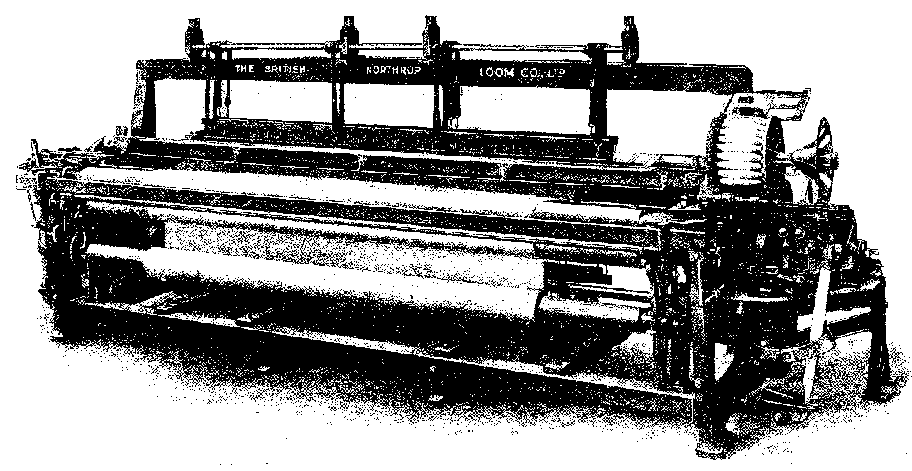
Advertisement: THE BRITISH NORTHROP LOOM CO., LTD.
Advertisement: FREDERICK SMITH & CO.
Advertisement: THE SKEFKO BALL BEARING CO., LTD.
Advertisement: PITMAN HANDBOOKS: ARITHMETIC
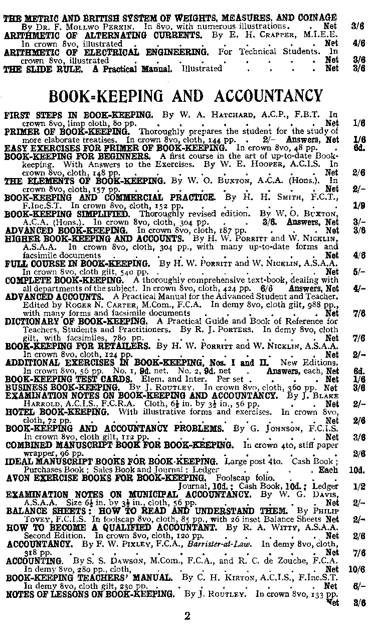
Advertisement: PITMAN HANDBOOKS: BOOK-KEEPING &
ACCOUNTANCY
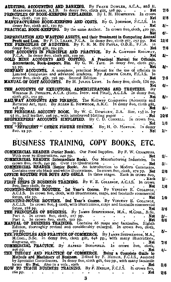
Advertisement: PITMAN HANDBOOKS: BUSINESS TRAINING
Advertisement: PITMAN HANDBOOKS: CIVIL SERVICE
Advertisement: PITMAN HANDBOOKS: ENGLISH, HISTORY
Advertisement: PITMAN HANDBOOKS: ECONOMICS, BANKING
Advertisement: PITMAN HANDBOOKS: INSURANCE, SHIPPING, INCOME
TAX
Advertisement: PITMAN HANDBOOKS: ADMINISTRATION,
ADVERTISING
Advertisement: PITMAN HANDBOOKS: HANDBOOKS, REFERENCE
Advertisement: PITMAN HANDBOOKS: COMMODITIES, LAW
Advertisement: PITMAN HANDBOOKS: FRENCH
Advertisement: PITMAN HANDBOOKS: GERMAN, SPANISH
Advertisement: PITMAN HANBOOKS: ITALIAN, SHORTHAND
Advertisement: PITMAN HANDBOOKS: SHORTHAND DICTIONARIES,
PHRASES
Advertisement: PITMAN HANDBOOKS: SHORTHAND SPEED PRACTICE,
READING
Advertisement: PITMAN HANDBOOKS: TEACHING, TYPEWRITING,
PERIODICALS
Advertisement: HENRY TAYLOR & SONS, LTD., PITMAN'S
BOOKS
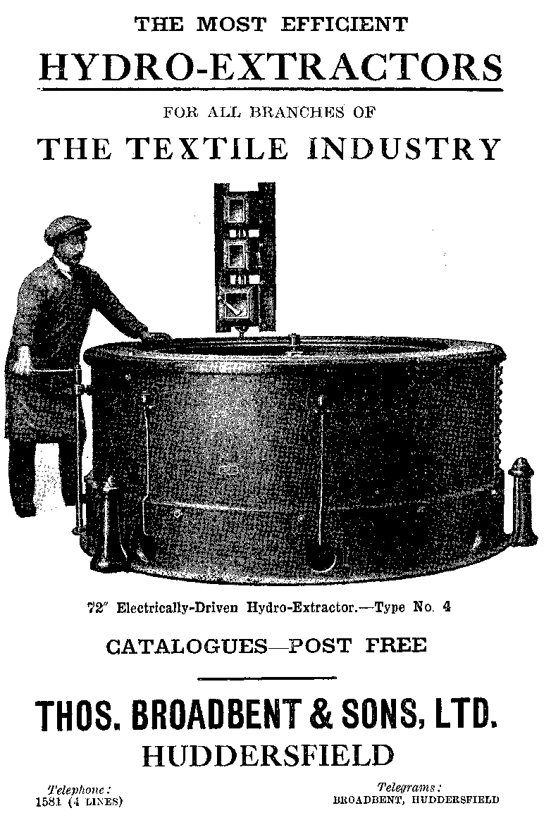
Advertisement: THOS. BROADBENT & SONS, LTD.
This eBook is for the use of anyone anywhere in the United States and most other parts of the world at no cost and with almost no restrictions whatsoever. You may copy it, give it away or re-use it under the terms of the Project Gutenberg License included with this eBook or online at www.gutenberg.org. If you are not located in the United States, you will have to check the laws of the country where you are located before using this eBook.